Toshiba TOSVERT VF-nC3 Manual
Variable speed drive
Hide thumbs
Also See for TOSVERT VF-nC3:
- Instruction manual (254 pages) ,
- Instruction manual (243 pages) ,
- Instruction manual (243 pages)
Advertisement
Quick Links
Advertisement

Related Manuals for Toshiba TOSVERT VF-nC3


Summary of Contents for Toshiba TOSVERT VF-nC3
- Page 1 Variable Speed Drive...
- Page 2 Built-in RS485 communication enable to control the inverter and build network. ◯ Communication rate : 38.4 kbps max. ◯ Compatible with the Modbus RTU and Toshiba protocols. You can connect a PC to manage parameters and monitor operating conditions.
- Page 3 1. VF-nC3 can be controlled simultaneously through RS485 communication. 2. Each inverter can switch among multiple motors if their operations do not overlap in the course of a work process. The VF-nC3 can toggle between the basic settings for two motors. 3.
- Page 4 The inverter input voltage (DC detection) (%/V) is displayed. ( In case of = ) Base frequency voltage 1&2...
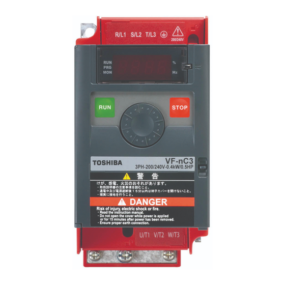
- Page 5 Explanation of the name plate label Digital setting: within ±0.1% of the max. frequency (-10 to +60°C) Analog setting: within ±1.0% of the max. frequency (25°C ±10°C) V/f constant, variable torque, automatic torque boost, vector control, automatic energy-saving. Auto-tuning. Base frequency (20 - 400Hz) adjusting to 1 & 2, torque boost (0 - 30%) adjusting to 1 & 2, adjusting frequency at start (0.1 - 10Hz) 3-phase 240V class Setting dial on the front panel, external frequency potentiometer (connectable to a potentiometer with a rated impedance of 1k - 10k ), Item...
- Page 6 3-pahse 240V class: three-phase 200 to 240V-50/60Hz R/L1,S/L2,T/L3 * Single-phase input: R/L1 and S/L2/N terminals Standard connection diagram-(sink logic) Standard connection diagram-(source logic) U/T1,V/T2,W/T3 (Negative)(common:CC) (Positive)(common:P24) PC/- DC reactor (DCL) *2 , *5 (option) DC reactor (DCL) PO, PA/+ *2 , *5 (option) PA/+ PC/- PA/+...
- Page 7 0, 1, 2, 18, 52 0, 1, 2, 18, 52 0.1: - 2: Preset speed guidance 3: Analog signal operation guidance 4: Motor 1 2 switching operation guidance 5: Motor constant setting guidance VI Input point 1 setting VI Input point 1 frequency VI Input point 2 setting VI Input point 2 frequency Logic output/pulse train output selection (OUT)
- Page 8 S/L2/N Note1) Note 1: Use the portion where the varnish around the installation hole is removed for wiring grounding wire. Approx. Inverter type Dimensions(mm) Terminal Model Rating mass (Terminal block VFNC3- VFNC3S- (kg) 3-phase 200V class PFL-2001S 2001P,2002P 105 65 115 90 M 3.5 -1.7A-50/60Hz 3-phase 200V class...
- Page 9 USB cable(A-B connection type). USB a commercially available USB cable. (Compliant with USB1.1/2.0) 45° Recommended cable length : 1m or less 13.2 TOSHIBA 4 0 H z 8 0 H z -1mA d c QS 6 0 T 1 0...
- Page 10 devices" because the maximum torque is decreased by the voltage dropping. Moreover, please pay attention to select leakage circuit breakers. underwater motors have higher rated When the lengths of the motor cable are long, please use thicker cable than a table of "Wiring...
- Page 11 Toshiba variable speed drive is incorporated or to any equipment that is used in combination with the Toshiba variable speed drive. Nor shall Toshiba, its subsidiaries, a iliates or agents be liable for...