Advertisement
Quick Links
Version 1.1
Published January 2020
Copyright©2020 ASRock INC. All rights reserved.
Copyright Notice:
No part of this documentation may be reproduced, transcribed, transmitted, or
translated in any language, in any form or by any means, except duplication of
documentation by the purchaser for backup purpose, without written consent of
ASRock Inc.
Products and corporate names appearing in this documentation may or may not
be registered trademarks or copyrights of their respective companies, and are used
only for identification or explanation and to the owners' benefit, without intent to
infringe.
Disclaimer:
Specifications and information contained in this documentation are furnished for
informational use only and subject to change without notice, and should not be
constructed as a commitment by ASRock. ASRock assumes no responsibility for
any errors or omissions that may appear in this documentation.
With respect to the contents of this documentation, ASRock does not provide
warranty of any kind, either expressed or implied, including but not limited to
the implied warranties or conditions of merchantability or fitness for a particular
purpose.
In no event shall ASRock, its directors, officers, employees, or agents be liable for
any indirect, special, incidental, or consequential damages (including damages for
loss of profits, loss of business, loss of data, interruption of business and the like),
even if ASRock has been advised of the possibility of such damages arising from any
defect or error in the documentation or product.
This device complies with Part 15 of the FCC Rules. Operation is subject to the following
two conditions:
(1) this device may not cause harmful interference, and
(2) this device must accept any interference received, including interference that
may cause undesired operation.
CALIFORNIA, USA ONLY
The Lithium battery adopted on this motherboard contains Perchlorate, a toxic substance
controlled in Perchlorate Best Management Practices (BMP) regulations passed by the
California Legislature. When you discard the Lithium battery in California, USA, please
follow the related regulations in advance.
"Perchlorate Material-special handling may apply, see www.dtsc.ca.gov/hazardouswaste/
perchlorate"
ASRock Website: http://www.asrock.com
Advertisement

Related Manuals for ASROCK Z490 Extreme4


Summary of Contents for ASROCK Z490 Extreme4
- Page 1 (including damages for loss of profits, loss of business, loss of data, interruption of business and the like), even if ASRock has been advised of the possibility of such damages arising from any defect or error in the documentation or product.
- Page 2 You are also entitled to have the goods repaired or replaced if the goods fail to be of acceptable quality and the failure does not amount to a major failure. If you require assistance please call ASRock Tel : +886-2-28965588 ext.123 (Standard International call charges apply) The terms HDMI®...
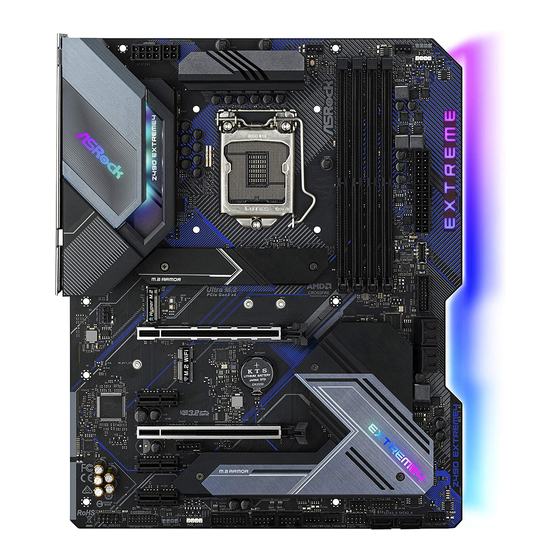
- Page 3 Z490 Extreme4 Motherboard Layout...
- Page 4 No. Description 12V Power Connector (ATX12V1) CPU Fan Connector (CPU_FAN1) 2 x 288-pin DDR4 DIMM Slots (DDR4_A1, DDR4_B1) 2 x 288-pin DDR4 DIMM Slots (DDR4_A2, DDR4_B2) CPU/Water Pump Fan Connector (CPU_FAN2/WP_3A) Addressable LED Header (ADDR_LED2) RGB LED Header (RGB_LED2) ATX Power Connector (ATXPWR1) Front Panel Type C USB 3.2 Gen1 Header (USB31_TC_2) USB 3.2 Gen1 Header (USB3_5_6) SATA3 Connector (SATA3_2)
- Page 5 Z490 Extreme4 I/O Panel No. Description No. Description USB 2.0 Ports (USB_1_2) Microphone (Pink) USB 3.2 Gen2 Type-A Port (USB31_TA_1) Optical SPDIF Out Port 2.5G LAN RJ-45 Port (Dragon RTL8125BG)* 10 USB 3.2 Gen1 Ports (USB3_12)*** Central / Bass (Orange) USB 3.2 Gen2 Type-C Port (USB31_TC_1)
- Page 6 ** If you use a 2-channel speaker, please connect the speaker’s plug into “Front Speaker Jack”. See the table below for connection details in accordance with the type of speaker you use. Audio Output Front Speaker Rear Speaker Central / Bass Line In Channels (No.
- Page 7 ASRock’s website without further notice. If you require technical support related to this motherboard, please visit our website for specific information about the model you are using. You may find the latest VGA cards and CPU support list on ASRock’s website as well. ASRock website http://www.asrock.com.
- Page 8 • 4 x DDR4 DIMM Slots • Supports DDR4 4266+(OC)*/4133(OC)/4000 (OC)/3866(OC)/3800(OC)/3733(OC)/3600(OC)/3200 (OC)/2933/2800/2666/2400/2133 non-ECC, un-buffered memory * Please refer to Memory Support List on ASRock's website for more information. (http://www.asrock.com/) * Core (i9/i7) support DDR4 up to 2933; Core (i5/i3), Pentium® and Celeron® support DDR4 up to 2666.
- Page 9 Z490 Extreme4 Graphics • Intel® UHD Graphics Built-in Visuals and the VGA outputs can be supported only with processors which are GPU integrated. • Hardware Accelerated Codecs: AVC/H.264, HEVC/H.265 8bit, HEVC/H.265 10bit, VP8, VP9 8bit, VP9 10bit, MPEG 2, MJPEG, VC-1 * VP9 10bit and VC-1 are for decode only.
- Page 10 • 2.5 Gigabit LAN 10/100/1000/2500 Mb/s • Dragon RTL8125BG • Supports Dragon 2.5G LAN Software - Smart Auto Adjust Bandwidth Control - Visual User Friendly UI - Visual Network Usage Statistics - Optimized Default Setting for Game, Browser, and Streaming Modes - User Customized Priority Control • Supports Wake-On-LAN • Supports Lightning/ESD Protection...
- Page 11 • 1 x 8 pin 12V Power Connector (Hi-Density Power Connec- tor) • 1 x 4 pin 12V Power Connector (Hi-Density Power Connec- tor) • 1 x Front Panel Audio Connector • 1 x Thunderbolt AIC Connector (5-pin) (Supports ASRock Thunderbolt 3 AIC R2.0 Card only)
- Page 12 • ErP/EuP ready (ErP/EuP ready power supply is required) * For detailed product information, please visit our website: http://www.asrock.com Please realize that there is a certain risk involved with overclocking, including adjusting the setting in the BIOS, applying Untied Overclocking Technology, or using third-party overclocking tools.
- Page 13 Z490 Extreme4 Chapter 2 Installation This is an ATX form factor motherboard. Before you install the motherboard, study the configuration of your chassis to ensure that the motherboard fits into it. Pre-installation Precautions Take note of the following precautions before you install motherboard components or change any motherboard settings.
- Page 14 2.1 Installing the CPU 1. Before you insert the 1200-Pin CPU into the socket, please check if the PnP cap is on the socket, if the CPU surface is unclean, or if there are any bent pins in the socket. Do not force to insert the CPU into the socket if above situation is found. Otherwise, the CPU will be seriously damaged.
- Page 15 Z490 Extreme4...
- Page 16 Please save and replace the cover if the processor is removed. The cover must be placed if you wish to return the motherboard for after service.
- Page 17 Z490 Extreme4 2.2 Installing the CPU Fan and Heatsink...
- Page 18 2.3 Installing Memory Modules (DIMM) This motherboard provides four 288-pin DDR4 (Double Data Rate 4) DIMM slots, and supports Dual Channel Memory Technology. 1. For dual channel configuration, you always need to install identical (the same brand, speed, size and chip-type) DDR4 DIMM pairs. 2.
- Page 19 Z490 Extreme4...
- Page 20 2.4 Expansion Slots (PCI Express Slots) There are 5 PCI Express slots on the motherboard. Before installing an expansion card, please make sure that the power supply is switched off or the power cord is unplugged. Please read the documentation of the expansion card and make necessary hardware settings for the card before you start the installation.
- Page 21 Z490 Extreme4 2.5 Jumpers Setup The illustration shows how jumpers are setup. When the jumper cap is placed on the pins, the jumper is “Short”. If no jumper cap is placed on the pins, the jumper is “Open”. Clear CMOS Jumper...
- Page 22 2.6 Onboard Headers and Connectors Onboard headers and connectors are NOT jumpers. Do NOT place jumper caps over these headers and connectors. Placing jumper caps over the headers and connectors will cause permanent damage to the motherboard. System Panel Header Connect the power PLED+ PLED-...
- Page 23 Z490 Extreme4 Serial ATA3 Connectors These six SATA3 (SATA3_0: connectors support SATA see p.1, No. 14) data cables for internal (SATA3_1: storage devices with up to see p.1, No. 13) 6.0 Gb/s data transfer rate. (SATA3_2: * If M2_2 is occupied by see p.1, No.
- Page 24 Front Panel Type C USB There is one Front 3.2 Gen1 Header Panel Type C USB 3.2 (20-pin USB31_TC_2) Gen1 Header on this (see p.1, No. 9) motherboard. This header is used for connecting a USB 3.2 Gen1 module for additional USB 3.2 Gen1 USB Type-C Cable ports.
- Page 25 Z490 Extreme4 CPU Fan Connector This motherboard FAN_SPEED_CONTROL CPU_FAN_SPEED (4-pin CPU_FAN1) provides a 4-Pin CPU fan FAN_VOLTAGE (see p.1, No. 2) (Quiet Fan) connector. If you plan to connect a 3-Pin CPU fan, please connect it to Pin 1-3. CPU/Water Pump Fan...
- Page 26 ATX 12V Power Connecting an ATX Connector 12V 4-pin cable here is (4-pin ATX12V2) optional. (see p.1, No. 34) *The power supply plug fits into this connector in only one orientation. Thunderbolt AIC Please connect a Thunderbolt™ Connectors add-in card (AIC) to the (5-pin TB1) Thunderbolt AIC connector via (see p.1, No.
- Page 27 Z490 Extreme4 Addressable LED Headers These two Addressable headers (3-pin ADDR_LED1) are used to connect Addressable (see p.1, No. 30) DO_ADDR LED extension cable which VOUT (3-pin ADDR_LED2) allows users to choose from (see p.1, No. 6) various LED lighting effects.
- Page 28 2.8 M.2 WiFi/BT Module and Intel® CNVi (Integrated WiFi/BT) Installation Guide The M.2, also known as the Next Generation Form Factor (NGFF), is a small size and versatile card edge connector that aims to replace mPCIe and mSATA. The M.2 Socket (Key E) supports type 2230 WiFi/BT module and Intel®...
- Page 29 Z490 Extreme4 Step 3 Gently insert the WiFi/BT module or Intel® CNVi (Integrated WiFi/ BT) into the M.2 slot. Please be aware that the module only fits in one orientation. Step 4 Tighten the screw with a screwdriver to secure the module into place.
- Page 30 2.9 M.2_SSD (NGFF) Module Installation Guide (M2_1) The M.2, also known as the Next Generation Form Factor (NGFF), is a small size and versatile card edge connector that aims to replace mPCIe and mSATA. The Hyper M.2 Sockets (M2_1) supports M Key type 2260/2280 M.2 PCI Express module up to Gen4 x4 (64 Gb/s) (Support with future processor only).
- Page 31 Z490 Extreme4 Step 3 Move the standoff based on the module type and length. The standoff is placed at the nut location B by default. Skip Step 3 and 4 and go straight to Step 5 if you are going to use the default nut.
- Page 32 XP941-512G (MZHPU512HCGL) SanDisk PCIe SD6PP4M-128G SanDisk PCIe SD6PP4M-256G TEAM PCIe3 x4 TM8FP2240G0C101 TEAM PCIe3 x4 TM8FP2480GC110 PCIe3 x4 WDS256G1X0C-00ENX0 (NVME) PCIe3 x4 WDS512G1X0C-00ENX0 (NVME) For the latest updates of M.2_SSD (NFGG) module support list, please visit our website for details: http://www.asrock.com...
- Page 33 Z490 Extreme4 2.10 M.2_SSD (NGFF) Module Installation Guide (M2_2 and M2_3) The M.2, also known as the Next Generation Form Factor (NGFF), is a small size and versatile card edge connector that aims to replace mPCIe and mSATA. The Ultra M.2 Socket (M2_2) supports M Key type 2260/2280 M.2 SATA3 6.0 Gb/s module and M.2 PCI...
- Page 34 Step 3 Before installing a M.2 (NGFF) SSD module, please loosen the screws to remove the M.2 heatsink. *Please remove the protective films on the bottom side of the M.2 heatsink before you install a M.2 SSD module. Step 4 Prepare the M.2 standoff that comes with the package.
- Page 35 Z490 Extreme4 M.2_SSD (NGFF) Module Support List Vendor Interface ADATA SATA3 AXNS330E-32GM-B ADATA SATA3 AXNS381E-128GM-B ADATA SATA3 AXNS381E-256GM-B ADATA SATA3 ASU800NS38-256GT-C ADATA SATA3 ASU800NS38-512GT-C ADATA PCIe3 x4 ASX7000NP-128GT-C ADATA PCIe3 x4 ASX8000NP-256GM-C ADATA PCIe3 x4 ASX7000NP-256GT-C ADATA PCIe3 x4 ASX8000NP-512GM-C...
- Page 36 SATA3 VLM100-120G-2280B-RD V-Color SATA3 VLM100-240G-2280RGB V-Color SATA3 VSM100-240G-2280 V-Color SATA3 VLM100-240G-2280B-RD SATA3 WDS100T1B0B-00AS40 SATA3 WDS240G1G0B-00RC30 PCIe3 x4 WDS256G1X0C-00ENX0 (NVME) PCIe3 x4 WDS512G1X0C-00ENX0 (NVME) For the latest updates of M.2_SSD (NFGG) module support list, please visit our website for details: http://www.asrock.com...
- Page 37 Z490 Extreme4 2.11 Nahimic Audio Nahimic audio software provides an incredible high definition sound technology which boosts the audio and voice performance of your system. Nahimic Audio interface is composed of four tabs : Audio, Microphone, Sound Tracker and Settings.
- Page 38 2.12 ASRock Polychrome SYNC ASRock Polychrome SYNC is a lighting control utility specifically designed for unique indi- viduals with sophisticated tastes to build their own stylish colorful lighting system. Simply by connecting the LED strip, you can customize various lighting schemes and patterns, including Static, Breathing, Strobe, Cycling, Music, Wave and more.
- Page 39 Z490 Extreme4 Connecting the Addressable RGB LED Strip Connect your Addressable RGB LED strips to the Addressable LED Headers (ADDR_LED1, ADDR_LED2) on the motherboard. ADDR_LED2 DO_ADDR VOUT ADDR_LED1 DO_ADDR VOUT 1. Never install the RGB LED cable in the wrong orientation; otherwise, the cable may be damaged.
- Page 40 ASRock Polychrome SYNC Utility Now you can adjust the RGB LED color through the ASRock Polychrome SYNC Utility. Download this utility from the ASRock Live Update & APP Shop and start coloring your PC style your way! Drag the tab to customize your preference.
- Page 41 Z490 Extreme4 1 Einleitung Vielen Dank, dass Sie sich für das Z490 Extreme4 von ASRock entschieden haben – ein zuverlässiges Motherboard, das konsequent unter der strengen Qualitätskontrolle von ASRock hergestellt wurde. Es liefert ausgezeichnete Leistung mit robustem Design, das ASRock Streben nach Qualität und Beständigkeit erfüllt.
- Page 42 Generation und höher • Digi Power design • 11-Leistungsphasendesign • Unterstützt Intel® Turbo Boost 3.0-Technologie • Unterstützt CPUs mit freiem Multiplikator der Intel® K-Serie • Unterstützt ASRock BCLK-Übertaktung (voller Bereich) • Unterstützt ASRock Hyper-BCLK-Engine III Chipsatz • Intel® Z490 Speicher •...
- Page 43 Z490 Extreme4 Grafikkarte • Integrierte Intel® UHD Graphics-Visualisierung und VGA- Ausgänge können nur mit Prozessoren unterstützt werden, die GPU-integriert sind. • Hardware-beschleunigende Codecs: AVC/H.264, HEVC/H.265 8 bit, HEVC/H.265 10 bit, VP8, VP9 8 bit, VP9 10 bit, MPEG2, MJPEG, VC-1 * VP9 10 Bit und VC-1 dienen nur der Dekodierung.
- Page 44 - Intelligente Bandbreitensteuerung mit automatischer Anpassung - Visuell ansprechende Benutzeroberfläche - Visuelle Netzwerknutzungsstatistiken - Optimierte Standardeinstellung für Spiel-, Browser- und Streaming-Modi - Nutzerangepasste Prioritätssteuerung • Unterstützt Wake-On-LAN • Unterstützt Schutz gegen Blitzschlag/elektrostatische Entladung • Unterstützt energieeffizientes Ethernet 802.3az • Unterstützt PXE Rückblende, •...
- Page 45 • 1 x 4-poliger 12-V-Netzanschluss (hochdichter Netzanschluss) • 1 x Audioanschluss an Frontblende • 1 x Thunderbolt Erweiterungskartenanschluss (5-polig) (Unterstützt nur ASRock Thunderbolt 3 AIC R2.0-Karten) • 2 x USB 2.0-Stiftleisten (unterstützt 4 USB 2.0-Ports) (Intel® Z490) (unterstützt Schutz gegen elektrostatische Entladung)
- Page 46 • ErP/EuP ready (ErP/EuP ready-Netzteil erforderlich) ungen * Detaillierte Produktinformationen finden Sie auf unserer Webseite: http://www.asrock.com Bitte beachten Sie, dass mit einer Übertaktung, zu der die Anpassung von BIOS- Einstellungen, die Anwendung der Untied Overclocking Technology oder die Nutzung von Übertaktungswerkzeugen von Drittanbietern zählen, bestimmte Risiken verbunden sind.
- Page 47 Z490 Extreme4 1.3 Jumpereinstellung Die Abbildung zeigt, wie die Jumper eingestellt werden. Wenn die Jumper-Kappe auf den Kontakten angebracht ist, ist der Jumper „kurzgeschlossen“. Wenn keine Jumper-Kappe auf den Kontakten angebracht ist, ist der Jumper „offen“. 2-poliger CMOS-löschen-Jumper Kurzgeschlossen: CMOS löschen...
- Page 48 1.4 Integrierte Stiftleisten und Anschlüsse Integrierte Stiftleisten und Anschlüsse sind KEINE Jumper. Bringen Sie KEINE Jumper-Kappen an diesen Stiftleisten und Anschlüssen an. Durch Anbringen von Jumper-Kappen an diesen Stiftleisten und Anschlüssen können Sie das Motherboard dauerhaft beschädigen. Systemblende-Stiftleiste Verbinden Sie Ein-/Austaste, PLED+ PLED- (9-polig, PANEL1)
- Page 49 Z490 Extreme4 Serial-ATA-III-Anschlüsse Diese sechs SATA-III- (SATA3_0: Anschlüsse unterstützen siehe S. 1, Nr. 14) SATA-Datenkabel für interne (SATA3_1: Speichergeräte mit einer Datenü siehe S. 1, Nr. 13) bertragungsgeschwindigkeit bis (SATA3_2: 6,0 Gb/s. siehe S. 1, Nr. 11) * Wenn M2_2 durch ein SATA-...
- Page 50 Type-C-USB-3.2 Gen1- Es gibt eine Type-C-USB-3.2 Stiftleiste für die Gen1-Stiftleiste für die Frontblende Frontblende an diesem (20-polig, USB31_TC_2) Motherboard. Diese Stiftleiste (siehe S. 1, Nr. 9) dient dem Anschluss eines USB-3.2 Gen1-Moduls für USB Type-C Cable zusätzliche USB-3.2 Gen1- Ports. Audiostiftleiste Diese Stiftleiste dient dem PRESENCE#...
- Page 51 Z490 Extreme4 CPU-Lüfteranschluss Dieses Motherboard bietet FAN_SPEED_CONTROL CPU_FAN_SPEED (4-polig, CPU_FAN1) einen 4-poligen CPU- FAN_VOLTAGE (siehe S. 1, Nr. 2) Lüfteranschluss (lautloser Lüfter). Falls Sie einen 3-poligen CPU-Lüfter anschließen möchten, verbinden Sie ihn bitte mit Kontakt 1 bis 3. CPU-/Wasserpumpen- Dieses Motherboard...
- Page 52 ATX-12-V-Netzanschluss An diesen Anschluss schließen (4-polig, ATX12V2) Sie ein ATX-12 V-Netzteil an. (siehe S. 1, Nr. 34) *Der Netzteilstecker passt nur in einer Richtung in diesen Anschluss. Thunderbolt- Bitte verbinden Sie Erweiterungskarten- eine Thunderbolt™- anschlüsse Erweiterungskarte über das (5-polig, TB1) GPIO-Kabel mit diesem (siehe S.
- Page 53 Z490 Extreme4 Adressierbare-LED- Diese beiden Adressierbare- Stiftleisten LED-Stiftleisten dienen dem DO_ADDR (3-polig, ADDR_LED1) Anschließen eines Adressierbare- VOUT (siehe S. 1, Nr. 30) LED-Erweiterungskabels, (3-polig, ADDR_LED2) das dem Nutzer die Auswahl (siehe S. 1, Nr. 6) zwischen verschiedenen LED- Lichteffekten ermöglicht.
- Page 54 1 Introduction Nous vous remercions d’avoir acheté cette carte mère ASRock Z490 Extreme4, une carte mère fiable fabriquée conformément au contrôle de qualité rigoureux et constant appliqué par ASRock. Fidèle à son engagement de qualité et de durabilité, ASRock vous garantit une carte mère de conception robuste aux performances élevées.
- Page 55 • Prend en charge la technologie Intel® Turbo Boost 3.0 • Prend en charge les processeurs débloqués de la série K Intel® • Prend en charge l’ o verclocking ASRock BCLK Full-range • Prend en charge le moteur Hyper BCLK III ASRock Chipset •...
- Page 56 Graphiques • La technologie Intel® UHD Graphics Built-in Visuals et les sorties VGA sont uniquement prises en charge par les processeurs intégrant un contrôleur graphique. • Codecs d’accélération matérielle : AVC/H.264, HEVC/H.265 8bit, HEVC/H.265 10bit, VP8, VP9 8bit, VP9 10bit, MPEG 2, MJPEG, VC-1 * VP9 10 bits et VC-1 sont uniquement destinés au décodage.
- Page 57 Z490 Extreme4 - Contrôle de la bande passante à réglage automatique intelligent - Interface visuelle conviviale - Statistiques d'utilisation du réseau visuel - Paramétrage par défaut optimisé pour les modes Jeu, Navigateur et Diffusion - Contrôle des priorités personnalisé par l'utilisateur •...
- Page 58 • 1 x connecteur d’alimentation 12 V 4 broches (connecteur d’alimentation haute densité) • 1 x connecteur audio panneau frontal • 1 x connecteur Thunderbolt AIC (5 broches) (Prise en charge de la carte ASRock Thunderbolt 3 AIC R2.0 uniquement)
- Page 59 • FCC, CE • ErP/EuP Ready (alimentation ErP/EuP ready requise) * pour des informations détaillées de nos produits, veuillez visiter notre site : http://www.asrock.com Il est important de signaler que l’ o verclocking présente certains risques, incluant des modifications du BIOS, l’ a pplication d’une technologie d’ o verclocking déliée et l’utilisation d’...
- Page 60 1.3 Configuration des cavaliers (jumpers) L’illustration ci-dessous vous renseigne sur la configuration des cavaliers (jumpers). Lorsque le capuchon du cavalier est installé sur les broches, le cavalier est « court-circuité ». Si le capuchon du cavalier n’ e st pas installé sur les broches, le cavalier est « ouvert ». Cavalier Cavalier Clear CMOS Court-circuité : Fonction Clear...
- Page 61 Z490 Extreme4 1.4 Embases et connecteurs de la carte mère Les embases et connecteurs situés sur la carte NE SONT PAS des cavaliers. Ne placez JAMAIS de capuchons de cavaliers sur ces embases ou connecteurs. Placer un capuchon de cavalier sur ces embases ou connecteurs endommagera irrémédiablement votre carte mère.
- Page 62 Connecteurs Serial ATA3 Ces six connecteurs SATA3 (SATA3_0: sont compatibles avec les voir p.1, No. 14) câbles de données SATA (SATA3_1: pour les appareils de stockage voir p.1, No. 13) internes avec un taux de (SATA3_2: transfert maximal de voir p.1, No. 11) 6,0 Go/s.
- Page 63 Z490 Extreme4 Embase USB 3.2 Gen1 Type C Cette carte mère comprend sur panneau avant une embase USB 3.2 Gen1 (USB31_TC_2 à 20 broches) Type C sur le panneau (voir p.1, No. 9) avant. Cette embase sert à connecter un module USB 3.2 Gen1 pour des...
- Page 64 Connecteur du ventilateur du Cette carte mère est dotée FAN_SPEED_CONTROL CPU_FAN_SPEED processeur d’un connecteur pour FAN_VOLTAGE (CPU_FAN1 à 4 broches) ventilateur de processeur (voir p.1, No. 2) (Quiet Fan) à 4 broches. Si vous envisagez de connecter un ventilateur de processeur à...
- Page 65 Z490 Extreme4 Connecteur d’alimentation Veuillez connecter une source ATX 12V d'alimentation ATX 12 V à ce (ATX12V2 à 4 broches) connecteur. (voir p.1, No. 34) *La fiche d'alimentation électrique s'adapte à ce connecteur dans un seul sens. Connecteurs Thunderbolt AIC Veuillez connecter une (TB1 à...
- Page 66 Embases LED adressables Ces deux embases adressables (ADDR_LED1 à 3 broches) servent à connecter le câble DO_ADDR (voir p.1, No. 30) d'extension LED adressable VOUT (ADDR_LED2 à 3 broches) qui permet aux utilisateurs de (voir p.1, No. 6) choisir parmi plusieurs effets lumineux LED.
- Page 67 Web per informazioni specifiche relative al modello attualmente in uso. È possibile trovare l'elenco di schede VGA più recenti e di supporto di CPU anche sul sito Web di ASRock. Sito Web di ASRock http://www.asrock.com.
- Page 68 • Potenza a 11 fasi • Supporta la tecnologia Intel® Turbo Boost 3.0 • Supporto di CPU unlocked Intel® K-Series • Supporta gamma completa overclocking BCLK ASRock • Supporto di ASRock Hyper BCLK Engine III Chipset • Intel® Z490 Memoria •...
- Page 69 Z490 Extreme4 • Codec con accelerazione hardware: AVC/H.264, HEVC/H.265 8-bit, HEVC/H.265 10-bit, VP8, VP9 8-bit, VP9 10-bit, MPEG2, MJPEG, VC-1 * VP9 10bit e VC-1 servono solo per la decodifica. * La codifica VP8 e VP9 non è supportata dal sistema operative Windows.
- Page 70 - Impostazioni predefinite ottimizzate per le modalità di Gioco, Navigazione e Streaming - Controllo priorità personalizzato dall'utentel • Supporto WOL (Wake-On-LAN) • Supporta protezione da fulmini/scariche elettrostatiche • Supporto Energy Efficient Ethernet 802.3az • Supporto PXE I/O pannello • 2 x porte antenna •...
- Page 71 Z490 Extreme4 ** Supporta la tecnologia Intel® Optane ** Supporto di SSD NVMe come disco d’avvio ** Supporta kit ASRock U.2 Connettore • 1 x connettore SPI TPM • 1 x connettore LED alimentazione e altoparlante • 2 x collettore LED RGB * Supporto totale di fino a 12V/3A, 36W strip LED •...
- Page 72 • FCC, CE • ErP/EuP Ready (è necessaria alimentazione ErP/EuP ready) * Per informazioni dettagliate sul prodotto, visitare il nostro sito Web: http://www.asrock.com Prestare attenzione al potenziale rischio previsto nella pratica di overclocking, inclusa la regolazione delle impostazioni nel BIOS, l'applicazione di tecnologia di Untied Overclocking o l'utilizzo di strumenti di overclocking di terze parti.
- Page 73 Z490 Extreme4 1.3 Impostazione jumper L'illustrazione mostra in che modo vengono impostati i jumper. Quando il cappuccio del jumper è posizionato sui pin, il jumper è "cortocircuitato". Se sui pin non è posizionato alcun cappuccio del jumper, il jumper è "aperto".
- Page 74 1.4 Header e connettori su scheda Gli header e i connettori sulla scheda NON sono jumper. NON posizionare cappucci del jumper su questi header e connettori. Il posizionamento di cappucci del jumper su header e connettori provocherà danni permanenti alla scheda madre. Header sul pannello del Collegare il tasto d'alimentazione, PLED+...
- Page 75 Z490 Extreme4 Connettori Serial ATA3 Questi sei connettori SATA3 (SATA3_0: supportano cavi dati SATA vedere pag.1, n. 14) per dispositivi di archiviazione (SATA3_1: interna, con una velocità di vedere pag. 1, n. 13) trasferimento dati fino a 6,0 Gb/s. (SATA3_2: * Se M2_2 è...
- Page 76 Connettore USB 3.2 Gen1 È presente un connettore tipo C pannello anteriore USB 3.2 Gen1 tipo C pannello (USB31_TC_2 a 20 pin) anteriore su questa scheda (vedere pag. 1, n. 9) madre. Questo connettore viene utilizzato per il collegamento di un modulo USB 3.2 Gen1 USB Type-C Cable per porte USB 3.2 Gen1 supplementari.
- Page 77 Z490 Extreme4 Connettore ventola CPU Questa scheda madre è dotata FAN_SPEED_CONTROL CPU_FAN_SPEED (CPU_FAN1 a 4 pin) di un connettore per la ventola FAN_VOLTAGE (vedere pag. 1, n. 2) della CPU (Ventola silenziosa) a 4 pin. Se si decide di collegare una ventola della CPU a 3 pin, collegarla al pin 1-3.
- Page 78 Connettori Thunderbolt Collegare una scheda aggiuntiva Thunderbolt™ (AIC) al (TB1 5-pin) connettore Thunderbolt AIC (vedere pag. 1, n. 32) utilizzando il cavo GPIO. *Installare la scheda AIC Thunderbolt™ su PCIE3 (slot predefinito). Connettore SPI TPM Questo connettore supporta il SPI_DQ3 +3.3V Dummy (SPI_TPM_J1 a 13 pin)
- Page 79 Z490 Extreme4 Header LED indirizzabili Questi due header LED (ADDR_LED1 a 3 pin) indirizzabili vengono utilizzati DO_ADDR (vedere pag. 1, n. 30) per collegare la prolunga LED VOUT (ADDR_LED2 a 3 pin) indirizzabile, che consente agli (vedere pag. 1, n. 6) utenti di scegliere tra vari effetti di illuminazione a LED.
- Page 80 Si esta documentación sufre alguna modificación, la versión actualizada estará disponible en el sitio web de ASRock sin previo aviso. Si necesita asistencia técnica relacionada con esta placa base, visite nuestro sitio web para obtener información específica sobre el modelo que esté...
- Page 81 • Compatible con DDR4 4266+(OC)*/4133(OC)/ 4000(OC)/3866(OC)/3800(OC)/3733(OC)/3600(OC)/Memoria no-ECC, sin búfer 3200(OC)/2933/2800/2666/2400/2133 * Para obtener más información, consulte la lista de memorias compatibles en el sitio web de ASRock. (http://www.asrock.com/) * Core (i9/i7) compatible con DDR4 de hasta 2933; Core (i5/ i3), Pentium® y Celeron® compatible con DDR4 de hasta 2666.
- Page 82 Gráficos • Intel® UHD Graphics Built-in Visuals y las salidas de VGA son compatibles únicamente con procesadores con GPU integrado. • Códecs acelerados por hardware: AVC/H.264, HEVC/H.265 8 bits, HEVC/H.265 10 bits, VP8, VP9 8 bits, VP9 10 bits, MPEG2, MJPEG, VC-1 * VP9 10 bits y VC-1 son solo para descodificación.
- Page 83 Z490 Extreme4 • 2,5 Gigabit LAN 10/100/1000/2500 Mb/s • Dragon RTL8125BG • Admite el software Dragon 2,5G LAN - Ajuste automático inteligente del control de ancho de banda - Interfaz de usuario sencilla visual - Estadísticas de uso de red visuales - Configuración predeterminada optimizada para juegos, el...
- Page 84 Intel® ** Admite unidad de estado sólido de NVMe como disco de arranque ** Admite el kit U.2 de ASRock Conector • 1 x Conector SPI TPM • 1 x LED de alimentación y base de conexiones para el altavoz • 2 x Cabezales de indicador LED RGB...
- Page 85 • Preparado para ErP/EuP (se necesita una fuente de alimentación preparada para ErP/EuP) * Para obtener información detallada del producto, visite nuestro sitio Web: http://www.asrock.com Tenga en cuenta que hay un cierto riesgo implícito en las operaciones de overclocking, incluido el ajuste de la BIOS, aplicando la tecnología de overclocking liberada o utilizando las herramientas de overclocking de otros fabricantes.
- Page 86 1.3 Instalación de los puentes La instalación muestra cómo deben instalarse los puentes. Cuando la tapa de puente se coloca en los contactos, el puente queda “Corto”. Si no coloca la tapa de puente en los contactos, el puente queda “Abierto”. Puente de borrado de Corto: Borrado de CMOS CMOS...
- Page 87 Z490 Extreme4 1.4 Conectores y cabezales incorporados Los cabezales y conectores incorporados NO son puentes. NO coloque tapas de puente sobre estos cabezales y conectores. Si coloca tapas de puente sobre los cabezales y conectores dañará de forma permanente la placa base.
- Page 88 Conectores Serie ATA3 Estos seis conectores SATA3 (SATA3_0: son compatibles con cables de consulte la pág. 1, nº 14) datos SATA para dispositivos de (SATA3_1: almacenamiento interno con una consulte la pág.1, nº 13) velocidad de transferencia de (SATA3_2: datos de hasta 6,0 Gb/s. consulte la pág.1, nº...
- Page 89 Z490 Extreme4 Cabezal de audio del panel Este cabezal se utiliza para PRESENCE# MIC_RET frontal conectar dispositivos de audio al OUT_RET (HD_AUDIO1 de 9 panel de audio frontal. contactos) OUT2_L (consulte la pág. 1, nº 31) J_SENSE OUT2_R MIC2_R MIC2_L 1.
- Page 90 Conector del ventilador de Esta placa base contiene FAN_SPEED_CONTROL CPU_FAN_SPEED la CPU un conector de ventilador FAN_VOLTAGE (CPU_FAN1 de 4 contactos) (ventilador silencioso) de (consulte la pág. 1, nº 2) CPU de 4 contactos. Si tiene pensando conectar un ventilador de CPU de 3 contactos, conéctelo al contacto 1-3.
- Page 91 Z490 Extreme4 Conector de alimentación Conecte una fuente de ATX de 12V alimentación ATX 12V en este (ATX12V2 de 4 contactos) conector. (consulte la pág. 1, nº 34) *El enchufe de la fuente de alimentación encaja en este conector en una única dirección.
- Page 92 Cabezales de LED Estas dos cabezales de LED direccionables direccionables se utilizan para DO_ADDR (ADDR_LED1 de 3 conectar el cable de la extensión VOUT contactos) LED direccionable que permite (consulte la pág. 1, nº 30) a los usuarios elegir entre varios (ADDR_LED2 de 3 efectos de iluminación de LED.
- Page 93 Z490 Extreme4 1 Введение Благодарим вас за приобретение надежной системной платы ASRock Z490 Extreme4, выпускаемой под постоянным жестким контролем качества компании ASRock. Эта материнская плата обеспечивает великолепную производительность и отличается надежной конструкцией в соответствии с требованиями компании ASRock в отношении качества и долговечности.
- Page 94 • Поддерживается технология Intel® Turbo Boost 3.0 • Поддержка процессоров Intel® серии K с разблокированным множителем • Поддержка полного разгона процессора ASRock BCLK • Поддержка системы ASRock Hyper BCLK Engine III Чипсет • Intel® Z490 Память • Двухканальная память DDR4 •...
- Page 95 Z490 Extreme4 Графическая • Встроенный видеоадаптер Intel® UHD Graphics и выходы VGA поддерживаются только при использовании ЦП со подсистема встроенными графическими процессорами. • Кодеки с аппаратным ускорением Hardware Accelerated Codecs: AVC/H.264, HEVC/H.265 8 бит, HEVC/H.265 10 бит, VP8, VP9 8 бит, VP9 10 бит, MPEG2, MJPEG, VC-1 * VP9 10 бит...
- Page 96 • 2,5 Gigabit LAN 10/100/1000/2500 Мб/с • Dragon RTL8125BG • Поддержка ПО Dragon 2,5G LAN - Управление пропускной способностью с интеллектуальной автонастройкой - Наглядный удобный пользовательский интерфейс - Наглядная статистика использования сети - Оптимизированная настройка по умолчанию параметров Игра, Браузер и Режимов потоковой передачи - Настраиваемое...
- Page 97 • 1 разъем питания 12 В (8-контактный разъем питания высокой плотности) • 1 разъем питания 12 В (4-контактный разъем питания высокой плотности) • 1 аудиоразъем для передней панели • 1 AIC-разъем Thunderbolt (5-контактный) (Поддерживает только карту ASRock Thunderbolt 3 AIC R2.0)
- Page 98 • FCC, CE • Совместимость с ErP/EuP (необходим блок питания, соответствующий стандарту ErP/EuP) * С дополнительной информацией об изделии можно ознакомиться на веб-сайте: http://www.asrock.com Следует учитывать, что разгон процессора, включая изменение настроек BIOS, применение технологии Untied Overclocking и использование инструментов разгона...
- Page 99 Z490 Extreme4 1.3 Установка перемычек Установка перемычек показана на рисунке. При установке перемычки-колпачка на контакты перемычка «замкнута». Если перемычка-колпачок на контакты не установлена, перемычка «разомкнута». Перемычка сброса Замкнута: Сброс настроек настроек CMOS CMOS 2-контактная (CLRMOS1) Разомкнута: По умолчанию перемычка (см. стр. 1, № 27) CLRMOS1 используется...
- Page 100 1.4 Колодки и разъемы, расположенные на системной плате Расположенные на системной плате колодки и разъемы НЕ являются перемычками. НЕ устанавливайте на эти колодки и разъемы перемычки-колпачки. Установка перемычек-колпачков на эти колодки и разъемы может вызвать неустранимое повреждение системной платы. Колодка системной Подключите...
- Page 101 Z490 Extreme4 Разъемы Serial ATA3 Эти шесть разъемов (SATA3_0: SATA3 предназначены для см. стр.1,№ 14) подключения кабелей SATA (SATA3_1: внутренних запоминающих см. стр. 1, № 13) устройств для передачи (SATA3_2: данных со скоростью до см. стр. 1, № 11) 6,0 Гб/с.
- Page 102 Аудиоколодка передней Эта колодка предназначена PRESENCE# панели MIC_RET для подключения OUT_RET (9-контактов, HD_ аудиоустройств к передней AUDIO1) аудиопанели. OUT2_L (см. стр. 1, № 31) J_SENSE OUT2_R MIC2_R MIC2_L 1. Аудиосистема высокого разрешения поддерживает функцию распознавания разъема, но для е правильной работы необходимо, чтобы провод панели корпуса...
- Page 103 Z490 Extreme4 Разъем вентилятора Эта материнская плата FAN_SPEED_CONTROL CPU_FAN_SPEED охлаждения процессора снабжена 4-контактным FAN_VOLTAGE (4-контакта, CPU_FAN1) разъемом для малошумящего (см. стр. 1, № 2) вентилятора ЦП. Если вы собираетесь подключить 3-контактный вентилятор охлаждения процессора, подключайте его к контактам 1-3. Разъем для вентилятора...
- Page 104 Разъем питания АТХ 12 В К данному разъему (4-контактов, ATX12V2) подключается источник (см. стр. 1, № 34) питания ATX 12 В. *Разъем от блока питания подсоединяется к этому разъему только в одной ориентации. Разъемы Thunderbolt AIC Подключите плату расширения (5 контактов, TB1) (AIC) Thunderbolt™...
- Page 105 Z490 Extreme4 Колодки адресуемой Эти две колодки для светодиодной подсветки адресуемой светодиодной DO_ADDR (3 контакта, ADDR_ подсветки служат для VOUT LED1) подключения удлинительного (см. стр. 1, № 30) кабеля адресуемой (3 контакта, ADDR_ светодиодной подсветки, LED2) которая позволяет реализовать (см. стр. 1, № 6) различные...
- Page 106 1 Introdução Obrigado por adquirir a placa mãe ASRock Z490 Extreme4, uma confiável placa mãe ASRock produzida sob rigoroso controle de qualidade consistente. Esta placa principal oferece um excelente desempenho com um design robusto em conformidade com o compromisso da ASRock em fabricar produtos de qualidade e resistentes.
- Page 107 • 4 x Slots DIMM DDR4 • Suporta memória DDR4 4266+(OC)*/4133(OC)/4000 (OC)/3866(OC)/3800(OC)/3733(OC)/3600(OC)/3200 (OC)/2933/2800/2666/2400/2133 não-ECC, módulos de memória * Por favor, consulte a Lista de Suporte de Memória no site da ASRock para obter mais informação. (http://www.asrock.com/) * Core (i9/i7) support DDR4 up to 2933; Core (i5/i3), Pentium®...
- Page 108 Gráficos • Os gráficos incorporados Intel® UHD e as saídas VGA só podem ser suportados com processadores com GPU integrada. • Codecs Acelerados de Hardware: AVC/H.264, HEVC/H.265 8bit, HEVC/H.265 10bit, VP8, VP9 8bit, VP9 10bit, MPEG 2, MJPEG, VC-1 * VP9 10bit e VC-1 são apenas para decodificação. * Codificação VP8 e VP9 não são suportados pelo SO Windows.
- Page 109 Z490 Extreme4 - Configuração Padrão Otimizada para Modos de Jogo, Navegador e Transmissão - Controle de Prioridade Personalizado do Usuário • Suporta Wake-On-LAN • Oferece Suporte à Proteção de Relâmpago/ESD • Suporta Energy Efficient Ethernet 802.3az • Suporta PXE E/S do painel • 2 x Portas de Antena...
- Page 110 • 1 x Conector de energia 4-pinos 12V (Conector de energia de alta densidade) • 1 x Conector de áudio do painel frontal • 1 x Conector Thunderbolt AIC (5 pinos)(Suporta Cartão ASRock Thunderbolt 3 AIC R2.0 única) • 2 x Plataformas USB 2.0 (Suporta 4 portas USB 2.0) (Intel® Z490) (Suporta Proteção ESD)
- Page 111 • Preparada para ErP/EuP (é necessária uma fonte de alimentação preparada para ErP/EuP) * Para obter informações detalhadas sobre o produto, por favor, visite o nosso site: http://www.asrock.com Por favor, observe que existe um certo risco envolvendo overclocking, incluindo o ajuste das definições na BIOS, a aplicação de tecnologia Untied Overclocking ou a utilização de...
- Page 112 1.3 Configuração dos jumpers A imagem abaixo mostra como os jumpers são configurados. Quando a tampa do jumper é colocada nos pinos, o jumper é "Curto". Se não for colocada uma tampa de jumper nos pinos, o jumper é "Aberto". Apagar o Jumper CMOS Curto: Apagar CMOS (CLRMOS1)
- Page 113 Z490 Extreme4 1.4 Suportes e conectores onboard Os conectores e suportes onboard NÃO são jumpers. NÃO coloque tampas de jumpers sobre estes terminais e conectores. Colocar tampas de jumpers sobre os terminais e conectores irá causar danos permanentes à placa-mãe.
- Page 114 Conectores série ATA3 Estes seis conectores SATA3 (SATA3_0: suportam cabos de dados ver p.1, N.º 14) SATA para dispositivos de (SATA3_1: armazenamento interno com ver p.1, N.º 13) uma taxa de transferência de (SATA3_2: dados de até 6,0 Gb/s. ver p.1, N.º 11) * Se M2_2 é...
- Page 115 Z490 Extreme4 Painel Frontal Cabeçote USB Há um Painel Frontal 3.2 Gen1 Tipo C Cabeçote USB 3.2 Gen1 (USB31_TC_2 de 20 pinos) Tipo C nesta placa mãe. Este (ver p.1, N.º 9) cabeçote é utilizado para conectar um módulo USB 3.2 Gen1 a portas adicionais...
- Page 116 Conector da Ventoinha da Esta placa mãe inclui um FAN_SPEED_CONTROL CPU_FAN_SPEED conector de ventilador da FAN_VOLTAGE (CPU_FAN1 de 4 pinos) CPU (Ventilador silencioso) (ver p.1, N.º 2) de 4 pinos. Se você pretende conectar um ventilador da CPU de 3 pinos, por favor, conecte-o ao Pino 1-3.
- Page 117 Z490 Extreme4 Conector de alimentação de Por favor, ligue este conector 12V ATX a uma alimentação de força (ATX12V2 de 4 pinos) ATX 12V. (ver p.1, N.º 34) *O plugue de sua fonte de alimentação se encaixa neste conector apenas em uma orientação.
- Page 118 Cabeçotes LED Endereçáveis Esses dois cabeçotes LED (ADDR_LED1 3 pinos) Endereçáveis são usados para DO_ADDR (ver p.1, N.º 30) conectar o cabo de extensão de VOUT (ADDR_LED2 3 pinos) LED Endereçável que permite (ver p.1, N.º 6) que os usuários escolham entre vários efeitos de iluminação de LED.
- Page 119 Z490 Extreme4 1 Wprowadzenie Dziękujemy za zakupienie płyty głównej ASRock Z490 Extreme4, niezawodnej płyty głównej produkowanej z konsekwentnie wykonywaną przez firmę ASRock, rygorystyczną kontrolą jakości. Płyta ta zapewnia doskonałą jakość działania i solidną konstrukcję, spełniającą zobowiązanie firmy ASRock do dostarczania produktów o wysokiej jakości i wytrzymałości.
- Page 120 • Sekcja zasilania 11 Power Phase Design • Obsługa technologii Intel® Turbo Boost 3.0 • Obsługa odblokowanych CPU Intel® serii K • Obsługa pełnego przetaktowywania ASRock BCLK • Obsługa ASRock Hyper BCLK Engine III Chipset • Intel® Z490 Pamięć • Technologia pamięci Dual Channel DDR4 •...
- Page 121 Z490 Extreme4 Grafika • Wbudowana grafika Intel® UHD i wyjścia VGA są obsługiwane wyłącznie z procesorami, które mają zintegrowane GPU. • Hardware Accelerated Codecs: AVC/H.264, HEVC/H.265 8-bit, HEVC/H.265 10-bit, VP8, VP9 8-bit, VP9 10-bit, MPEG 2, MJPEG, VC-1 * VP9 10bit and VC-1 are for decode only.
- Page 122 - Graficzna statystyka wykorzystania sieci - Optymalizowane ustawienia domyślne dla gier, przeglądarki i trybów transmisji strumieniowej - Ustawiane przez użytkownika sterowanie priorytetami • Obsługa Wake-On-LAN • Obsługa zabezpieczenia przed wyładowaniami atmosferycznymi/ESD • Obsługa Energy Efficient Ethernet 802.3az • Obsługa PXE Tylny panel •...
- Page 123 Z490 Extreme4 ** Obsługa technologii Intel® Optane ** Obsługa SSD NVMe, jako dysków rozruchowych ** Obsługa ASRock U.2 Kit • 1 x złącze główkowe SPI TPM Złącze • 1 x dioda LED zasilania i złącze główkowe głośnika • 2 x złącza główkowe LED RGB * Obsługa łącznie do 12V/3A, pasek LED 36W...
- Page 124 • Gotowość do obsługi ErP/EuP (Wymagane zasilanie z gotowością obsługi ErP/EuP) * Dla uzyskania szczegółowej informacji o produkcie, należy odwiedzić naszą stronę internetową: http://www.asrock.com Należy pamiętać, że przetaktowywanie jest związane z pewnym ryzykiem, włącznie z regulacją ustawień w BIOS, zastosowaniem Untied Overclocking Technology lub używaniem narzędzi przetaktowywania innych firm.
- Page 125 Z490 Extreme4 1.3 Ustawienia zworek Ta ilustracja pokazuje ustawienia zworek. Po umieszczeniu nasadki zworki na pinach, zworka jest “Zwarta”. Jeśli nasadka zworki nie jest umieszczona na pinach, zworka jest “Otwarta”. Zworka usuwania danych Zwarcie: Usunięcie danych z z pamięci CMOS pamięci CMOS...
- Page 126 1.4 Wbudowane złącza główkowe i inne złącza Wbudowane złącza główkowe i inne złącza są bezzworkowe. NIE należy umieszczać zworek nad tymi złączami główkowymi i złączami. Umieszczanie zworek nad złączami główkowymi i złączami spowoduje trwałe uszkodzenie płyty głównej. Złącze główkowe na panelu Do tego złącza główkowego PLED+ PLED-...
- Page 127 Z490 Extreme4 Złącza Serial ATA3 Te sześć złączy SATA3 (SATA3_0: obsługuje kable danych sprawdź s.1, Nr 14) SATA dla zewnętrznych (SATA3_1: urządzeń pamięci z sprawdź s.1, Nr 13) szybkością transferu danych (SATA3_2: do 6,0 Gb/s. sprawdź s.1, Nr 11) * Jeśli gniazdo M2_2 jest...
- Page 128 Złącze główkowe Gen1 USB Na tej płycie głównej 3.2 typu C panelu przedniego dostępne jest jedno złącze (20-pinowe USB31_TC_2) główkowe Gen1 USB 3.2 (sprawdź s.1, Nr 9) typu C panelu przedniego. To złącze główkowe jest używane do podłączania modułu USB 3.2 Gen1 dla USB Type-C Cable dodatkowych portów USB 3.2 Gen1.
- Page 129 Z490 Extreme4 Złącze wentylatora CPU Ta płyta główna udostępnia FAN_SPEED_CONTROL CPU_FAN_SPEED (4-pinowe CPU_FAN1) 4-pinowe złącze wentylatora FAN_VOLTAGE (sprawdź s.1, Nr 2) CPU (Cichy wentylator). Jeśli planowane jest podłączenie 3-pinowego wentylatora CPU, należy je podłączyć do pinów 1-3. Złącze wentylatora pompy Ta płyta główna udostępnia...
- Page 130 Złącze zasilania ATX 12V Podłącz do tego złącza (4-pinowe ATX12V2) zasilacz ATX 12V. (sprawdź s.1, Nr 34) *Wtyczka zasilacza pasuje do tego złącza tylko w jednym kierunku. Złącza Thunderbolt AIC Podłącz dodatkową kartę (5-pinowe TB1) Thunderbolt™ (AIC) do złącza (sprawdź s.1, Nr 32) Thunderbolt AIC przez kabel GPIO.
- Page 131 Z490 Extreme4 Adresowalne złącza Te dwa adresowalne złącza główkowe LED główkowe są używane do DO_ADDR (3-pinowe ADDR_LED1) podłączenia adresowalnego VOUT (sprawdź s.1, Nr 30) przedłużacza LED, co (3-pinowe ADDR_LED2) umożliwia użytkownikom (sprawdź s.1, Nr 6) wybór spośród różnych efektów światła LED.
- Page 132 ASRock Z490 Extreme4 마더보드를 구입해 주셔서 감사합니다 . 이 마더보드는 ASRock 의 일관되고 엄격한 품질관리 하에 생산되어 신뢰성이 우수합니다 . 품질과 내구성에 대한 ASRock 의 기준에 부합하는 우수한 성능과 견고한 설계를 제공합니다 . 마더보드 규격과 BIOS 소프트웨어를 업데이트할 수도 있기 때문에 , 이 문서의...
- Page 133 • DDR4 DIMM 슬롯 4 개 • DDR4 4266+(OC)*/4133(OC)/4000(OC)/3866(OC)/ 3800(OC)/3733(OC)/3600(OC)/3200(OC)/2933/2800/2666/ 2400/2133 비 ECC, 비버퍼링 메모리 지원 * 추가 정보를 원하시면 ASRock 웹사이트에 있는 메모리 지원 목록을 참조하십시오 . (http://www.asrock.com/) * Core (i9/i7) 는 최대 2933 까지 DDR4 를 지원하고 ; Core (i5/i3), Pentium®...
- Page 134 • Intel® UHD 그래픽스 빌트 - 인 비주얼과 VGA 출력은 GPU 그래픽 통합 프로세서로만 지원할 수 있습니다 . • 하드웨어 가속 코덱 : AVC/H.264, HEVC/H.265 8- 비트 , HEVC/H.265 10- 비트 , VP8, VP9 8- 비트 , VP9 10- 비트 , MPEG 2, MJPEG, VC-1 * VP9 10 비트...
- Page 135 • Ultra M.2 소켓 (M2_3) 1 개 , M 키 타입 2260/2280/22110 M.2 SATA3 6.0 Gb/s 모듈 지원 및 Gen3 까지의 M.2 PCI Express 모듈 4 개 지원 (32 Gb/s)** ** Intel® Optane 기술 지원 ** NVMe SSD 를 부팅 디스크로 사용 가능하도록 지원 ** ASRock U.2 키트 지원...
- Page 136 • 4 핀 12V 전원 커넥터 1 개 ( 고밀도 전원 커넥터 ) • 전면 패널 오디오 커넥터 1 개 • Thunderbolt AIC 커넥터 1 개 (5 핀 ) (ASRock Thunderbolt 3 AIC R2.0 카드 만 지원 ) • USB 2.0 헤더 2 개 (USB 2.0 포트 4 개 지원 ) (Intel® Z490) (ESD 보호...
- Page 137 • FCC, CE 인증 • ErP/EuP 사용 가능 (ErP/EuP 사용 가능 전원공급장치 필요 ) * 자세한 제품 정보에 대해서는 당사 웹사이트를 참조하십시오 : http://www.asrock.com BIOS 설정을 조정하거나 Untied Overclocking Technology 를 적용하거나 타업체의 오버클로킹 도구를 사용하는 것을 포함하는 오버클로킹에는 어느 정도의 위험이...
- Page 138 1.3 점퍼 설정 그림은 점퍼를 어떻게 설정하는지 보여줍니다 . 점퍼 캡을 핀에 씌우면 점퍼가 “단락” 됩니다 . 점퍼 캡을 핀에 씌우지 않으면 점퍼가 “단선”됩니다 . Clear CMOS 점퍼 단락 : Clear CMOS (CLRMOS1) 단선 : 기본값 2 핀 점퍼 (1 페이지 , 27 번 항목 참조...
- Page 139 Z490 Extreme4 1.4 온보드 헤더 및 커넥터 온보드 헤더와 커넥터는 점퍼가 아닙니다 . 점퍼 캡을 온보드 헤더와 커넥터에 씌우지 마십시오 . 점퍼 캡을 온보드 헤더와 커넥터에 씌우면 마더보드가 영구적으로 손상됩 니다 . 섀시의 전원 버튼 , 리셋 시스템 패널 헤더...
- Page 140 시리얼 ATA3 커넥터 이들 6 개의 SATA3 커넥터는 (SATA3_0: 최대 6.0 Gb/s 데이터 전송 1 페이지 , 14 번 항목 참조 ) 속도를 제공하는 내부 (SATA3_1: 저장 장치용 SATA 데이터 1 페이지 , 13 번 항목 참조 ) 케이블을 지원합니다 . (SATA3_2: * SATA- 타입...
- Page 141 Z490 Extreme4 전면 패널 타입 C USB 3.2 이 마더보드에는 전면 패널 Gen1 헤더 타입 C USB 3.2 Gen1 헤더 (20 핀 USB31_TC_2) 1 개가 있습니다 . 이 헤더는 (1 페이지 , 9 번 항목 참조 ) 추가 USB 3.2 Gen1 포트용...
- Page 142 CPU 팬 커넥터 이 마더보드에는 4 핀 CPU FAN_SPEED_CONTROL CPU_FAN_SPEED (4 핀 CPU_FAN1) 팬 ( 저소음 팬 ) 커넥터가 FAN_VOLTAGE (1 페이지 , 2 번 항목 참조 ) 탑재되어 있습니다 . 3 핀 CPU 팬을 연결하려는 경우 핀 1-3 에 연결하십시오 . CPU/ 워터...
- Page 143 Z490 Extreme4 Thunderbolt ™ 확장 Thunderbolt AIC 커넥터 (5 핀 TB1) 카드 (AIC) 를 GPIO (1 페이지 , 32 번 항목 참조 ) 케이블로 Thunderbolt AIC 커넥터에 연결하십시오 . *Thunderbolt ™ AIC 카드를 PCIE3( 기본 슬롯 ) 에 설치하십시오 .
- Page 144 주소 지정 가능한 LED 헤더 이 2 개의 주소 지정 가능한 (3 핀 ADDR_LED1) LED 헤더는 다양한 LED DO_ADDR (1 페이지 , 30 번 항목 참조 ) 조명 효과를 선택할 수 있는 VOUT (3 핀 ADDR_LED2) 주소 주소 지정 가능한 LED (1 페이지...
- Page 145 アルの内容は予告なしに変更するこ とがあります。 このマニュアルの内容に変更 があった場合には、 更新されたバージョンは、 予告なくASRock のウェブサイ トから 入手できるようになります。 このマザーボードに関する技術的なサポートが必要な 場合には、 ご使用のモデルについての詳細情報を、 当社のウェブサイ トで参照く だ さい。 ASRock のウェブサイ トでは、 最新の VGA カードおよび CPU サポート一覧 もご覧になれます。 ASRock ウェブサイ ト http://www.asrock.com. 1.1 パッケージの内容 • ASRock Z490 Extreme4 マザーボード (ATX フォームファクタ) • ASRock Z490 Extreme4 クイックインストールガイ ド...
- Page 146 • Digi Power design • 11 電源フェーズ設計 • Intel® ターボブースト 3.0 テク ノロジーをサポート • Intel® K シリーズ アンロック CPU に対応 • ASRock BCLK フルレンジオーバークロッキングに対応 • ASRock ハイパー BCLK エンジン III に対応 チップセッ ト • Intel® Z490 • デュアルチャンネル DDR4 メモリ機能 メモリ...
- Page 147 Z490 Extreme4 • Intel® UHD グラフィ ックス内蔵ビジュアルおよび VGA 出力は、 グラフ ィ ックス GPU に統合されたプロセッサーのみでサポートされます。 • ハードウェア ・ アクセラレイティ ド ・ コーデック : AVC/H.264、 HEVC/H.265 8- ビッ ト、 HEVC/H.265 10- ビッ ト、 VP8、 VP9 8- ビ ッ ト、 VP9 10- ビッ ト、 MPEG 2、 MJPEG、 VC-1 * VP9 10 ビッ...
- Page 148 • 2.5 ギガビッ ト LAN 10/100/1000/2500 Mb/s • Dragon RTL8125BG • Dragon 2.5G LAN ソフトウェアに対応 - スマートに帯域幅制御を自動調整 - 見やすく使いやすい UI - 見やすいネッ トワーク使用統計情報 - ゲーム、 ブラウザ、 ストリーミングモードように最適化されたデ フォルト設定 - ユーザーカスタマイズによる優先度制御 • Wake-On-LAN (ウェイク オン ラン) に対応 • 雷 / 静電気放電 (ESD) 保護に対応 •...
- Page 149 までの M.2 PCI Express モジュールに対応 ** テク ノロジーに対応 ** Intel® Optane ** 起動ディスク として NVMe SSD に対応 ** ASRock U.2 キッ トに対応 • 1 x SPI TPM ヘッダー コネクタ • 1 x 電源 LED とスピーカーヘッダー • 2 x RGB LED ヘッダー...
- Page 150 1.05V、 VCCSA、 VCCST、 VCCIO • Microsoft® Windows® 10 64-bit 認証 • FCC、 CE • ErP/EuP Ready ( ErP/EuP 対応電源供給装置が必要です) * 商品詳細については、 当社ウェブサイ トをご覧く ださい。 http://www.asrock.com BIOS 設定の調整、 アンタイ ドオーバークロックテク ノロジーの適用、 サードパーティ のオーバークロックツールの使用などを含む、 オーバークロックには、 一定のリスク を伴いますのでご注意く ださい。 オーバークロックするとシステムが不安定になった り、 システムのコンポーネントやデバイスが破損するこ とがあります。 ご自分の責任...
- Page 151 Z490 Extreme4 1.3 ジャンパー設定 このイラストは、 ジャンパーの設定方法を示しています。 ジャンパーキャップがピンに被 さっていると、 ジャンパーは 「ショート」 です。 ジャンパーキャップがピンに被さっていない 場合には、 ジャンパーは 「オープン」 です。 CMOS クリアジャンパー ショート : CMOS のク リア オープン : デフォルト (CLRMOS1) 2 ピンジャン (p.1、 No. 27 参照) パー CLRMOS1 を使って CMOS 内のデータをクリアできます。 CMOS のデータには、 シ...
- Page 152 1.4 オンボードのヘッダーとコネクタ オンボードヘッダーとコネクタはジャンパーではありません。 これらヘッダーとコネクタ にはジャンパーキャップを被せないでく ださい。 ヘッダーおよびコネクタにジャンパー キャップを被せると、 マザーボードに物理損傷が起こるこ とがあります。 システムパネルヘッダー 電源ボタンを接続し、 ボタンを PLED+ PLED- (9 ピン PANEL1) リセッ トし、 下記のピン割り当て PWRBTN# (p.1、 No. 21 参照) に従って、 シャーシのシステムス テータス表示ランプをこのヘッ RESET# ダーにセッ トします。 ケーブルを HDLED- 接続するときには、 ピンの+と− HDLED+ に気をつけてく ださい。 PWRBTN (電源ボタン) : シャーシ前面パネルの電源ボタンに接続してく...
- Page 153 Z490 Extreme4 シリアル ATA3 コネクタ これら 6 つの SATA3 コネクター は、 最高 6.0 Gb/ 秒のデータ転 (SATA3_0: p.1、 No. 14 参照) 送速度で内部ストレージデバ イス用の SATA データケーブル (SATA3_1: p.1、 No. 13 参照) をサポートします。 * SATA タイプ M.2 デバイスで (SATA3_2: p.1、 No. 11 参照)...
- Page 154 フロントパネルタイプ C このマザーボード上には、 1 つ USB 3.2 Gen1 ヘッダー のフロントパネルタイプ C USB (20 ピン USB31_TC_2) 3.2 Gen1 ヘッダーがあります。 (p.1、 No. 9 参照) このヘッダーは、 追加 USB 3.2 Gen1 ポート用に USB 3.2 Gen1 モジュールを接続するために 使用されます。 USB Type-C Cable フロントパネルオーディ このヘッダーは、 フロントオー PRESENCE# MIC_RET オヘッダー...
- Page 155 Z490 Extreme4 CPU ファンコネクタ このマザーボードは 4 ピン FAN_SPEED_CONTROL CPU_FAN_SPEED (4 ピン CPU_FAN1) CPU ファン (静音ファン) コネク FAN_VOLTAGE (p.1、 No. 2 参照) タが装備されています。 3 ピン の CPU ファンを接続する場合 には、 ピン 1-3 に接続してく だ さい。 このマザーボードは 4 ピン水 CPU/ウォーターポンプフ FAN_SPEED_CONTROL CPU_FAN_SPEED ァンコネクタ...
- Page 156 Thunderbolt AIC コネクタ GPIO ケーブルを使って、 (5 ピン TB1) Thunderbolt ™ アドインカード (p.1、 No. 32 参照) (AIC) を Thunderbolt AIC コネ クターに接続してく ださい。 *PCIE3 ( デフォルトスロッ ト) に Thunderbolt ™ AIC カードを取り 付けてく ださい。 このコネクタは SPI トラステッ SPI TPM Header SPI_DQ3 +3.3V Dummy (SPI TPM ヘッダー)...
- Page 157 Z490 Extreme4 アドレサブル LED ヘッ これら 2 つのア ドレサブル LED ダー ヘッダーを使用して、 ア ドレサブ DO_ADDR (3 ピン ADDR_LED1) ル LED 延長ケーブルを接続す VOUT (p.1、 No. 30 参照) れば、 ユーザーは、 さまざまな (3 ピン ADDR_LED2) LED ライティ ング効果を選択で (p.1、 No. 6 参照) きます。...
- Page 158 恕不另行通知。如果本文档有任何修改,则更新的版本将发布在华擎网站上, 我们不会另外进行通知。如果您需要与此主板相关的技术支持,请访问我们的 网站以具体了解所用型号的信息。您也可以在华擎网站上找到最新 VGA 卡和 CPU 支持列表。华擎网站 http://www.asrock.com。 1.1 包装清单 • 华擎 Z490 Extreme4 主板(ATX 规格尺寸) • 华擎 Z490 Extreme4 快速安装指南 • 华擎 Z490 Extreme4 支持光盘 • 4 x 串行 ATA (SATA) 数据线(选购) • 4 x 螺丝(供 M.2 插座使用)(选购) • 2 x 螺母柱(供 M.2 插座使用)(选购)...
- Page 159 Z490 Extreme4 1.2 规格 • ATX 规格尺寸 平台 • 2 盎司纯铜电路板 • 支持第 10 代或最新一代 Intel® Core 处理器(1200 接口) • Digi Power design • 11 电源相设计 • 支持 Intel® Turbo Boost 3.0 技术 • 支持 Intel® K 系列不锁频 CPU • 支持华擎 BCLK 全范围超频...
- Page 160 • 只有 GPU 集成的处理器才支持 Intel® UHD Graphics 内置视效 图形 和 VGA 输出。 • 硬件加速编解码器:AVC/H.264、HEVC/H.265 8-bit、 HEVC/H.265 10-bit、VP8、VP9 8-bit、VP9 10-bit、MPEG 2、 MJPEG、VC-1 * VP9 10 位和 VC-1 仅用于解码。 * Windows 操作系统不支持 VP8 和 VP9 编码。 • 显卡、媒体和计算:Microsoft DirectX 12、OpenGL 4.5、 Intel® Built In Visuals、Intel® 高速视频同步、混合 / 可切换显 卡、OpenCL 2.1 • 显示和内容安全:Rec.
- Page 161 Z490 Extreme4 - 视效网络使用情况统计数据 - 游戏、浏览器和串流模式的默认设置进行了优化 - 用户定制优先级控制 • 支持 Wake-On-LAN(网上唤醒) • 支持雷电 /ESD 保护 • 支持高能效以太网 802.3az • 支持 PXE • 2 x 天线端口 后面板 I/O • 1 x PS/2 鼠标 / 键盘端口 • 1 x HDMI 端口 • 1 x DisplayPort 1.4 • 1 x 光学...
- Page 162 • 1 x SPI TPM 接脚 接口 • 1 x 电源 LED 和扬声器接脚 • 2 x RGB LED 接头 * 总共支持最高 12V/3A, 36W LED 灯条 • 2 x 可寻址 LED 接脚 * 总共支持最高 5V/3A, 15W LED 灯条 • 1 x CPU 风扇接口(4 针) * CPU 风扇接口支持最高...
- Page 163 Z490 Extreme4 • Microsoft® Windows® 10 64-bit 操作系统 • FCC、CE 认证 • ErP/EuP 支持(需要支持 ErP/EuP 的电源) * 有关详细产品信息,请访问我们的网站:http://www.asrock.com 须认识到超频会有一定风险,包括调整 BIOS 设置,应用“自由超频技术”,或 使用第三方超频工具。超频可能会影响到系统的稳定性,甚至对系统的组件和设 备造成损坏。执行这项工作您应自担风险和费用。我们对由于超频而造成的损坏 概不负责。...
- Page 164 1.3 跳线设置 此图显示如何设置跳线。将跳线帽装到这些针脚上时,跳线“短接”。如果这些针脚 上没有装跳线帽,跳线“开路”。 清除 CMOS 跳线 短接 : 清除 CMOS (CLRMOS1) 开路 : 默认 2 针跳线 (见第 1 页,第 27 个) CLRMOS1 允许您清除 CMOS 中的数据。CMOS 中的数据包括系统设置信息,如 系统密码、日期、时间和系统设置参数。要清除和重置系统参数为默认设置,请 关闭计算机,拔下电源线插头,然后使用跳线帽短接 CLRMOS1 上的针脚 3 秒。请 记住在清除 CMOS 后取下跳线帽。如果您需要在刚完成 BIOS 更新后清除 CMOS, 则必须先启动系统,并在关闭后再执行清除 CMOS 操作。...
- Page 165 Z490 Extreme4 1.4 板载接脚和接口 板载接脚和接口不是跳线。不要将跳线帽装到这些接脚和接口上。将跳线帽装到这些 接脚和接口上将会对主板造成永久性损坏。 系统面板接头 按照下面的针脚分配,将机箱 PLED+ PLED- (9 针 PANEL1) PWRBTN# 上的电源按钮、重置按钮和系 (见第 1 页,第 21 个) 统状态指示灯连接到此接脚。 在连接线缆前请记下正负针 RESET# 脚。 HDLED- HDLED+ PWRBTN(电源按钮): 连接到机箱前面板上的电源按钮。您可以配置使用电源按钮关闭系统的方式。 RESET(重置按钮): 连接到机箱前面板上的重置按钮。如果计算机死机,无法执行正常重新启动,按重置 按钮重新启动计算机。 PLED(系统电源 LED): 连接到机箱前面板上的电源状态指示灯。系统操作操作时,此 LED 亮起。系统处在 S1/S3 睡眠状态时,此 LED 闪烁。系统处在 S4 睡眠状态或关机 (S5) 时,此 LED 熄灭。...
- Page 166 串行 ATA3 接口 这六个 SATA3 接口支持最高 (SATA3_0: 6.0 Gb/s 数据传输速率的内部 见第 1 页,第 14 个) 存储设备的 SATA 数据线。 (SATA3_1: * 如果 M2_2 被 SATA 型 M.2 见第 1 页,第 13 个) 设备占用,SATA3_1 将被禁 (SATA3_2: 用。 见第 1 页,第 11 个) * 如果...
- Page 167 Z490 Extreme4 前面板类型 C USB 3.2 此主板上有一个前面板类型 C Gen1 接脚 USB 3.2 Gen1 接脚。此接脚用 (20- 针 USB31_TC_2) 于连接 USB 3.2 Gen1 模块以 (见第 1 页,第 9 个) 获得附加 USB 3.2 Gen1 端口。 USB Type-C Cable 前面板音频接头 此接头用于将音频设备连接 PRESENCE# MIC_RET (9 针 HD_AUDIO1) 到前音频面板。...
- Page 168 CPU 风扇接口 此主板提供 4 针 CPU 风扇 FAN_SPEED_CONTROL CPU_FAN_SPEED (4 针 CPU_FAN1) FAN_VOLTAGE (静音风扇)接口。如果您 (见第 1 页,第 2 个) 打算连接 3 针 CPU 风扇,请 将它连接到针脚 1-3。 CPU/ 水泵风扇接口 此主板提供 4 针水冷风扇接 FAN_SPEED_CONTROL CPU_FAN_SPEED (4 针 CPU_FAN2/ 口。如果您打算连接 3 针 FAN_VOLTAGE WP_3A) CPU 水冷风扇,请将它连接...
- Page 169 Z490 Extreme4 SPI TPM 接脚 SPI_DQ3 此接口支持 SPI Trusted Platform +3.3V Dummy (13 针 SPI_TPM_J1) Module(信任平台模块, SPI_MOSI (见第 1 页,第 17 个) TPM)系统,可以安全地存储 RST# TPM_PIRQ 密钥、数字证书、密码和数据。 TPM 系统也可以帮助增强网络 SPI_TPM_CS# 安全,保护数字身份和确保平 RSMRST# 台完整性。 SPI_MISO SPI_CS0 SPI_DQ2 RGB LED 接脚 这两个 RGB 接脚用于连接 RGB (4 针...
- Page 170 电子信息产品污染控制标示 依据中国发布的「电子信息产品污染控制管理办法」及 SJ/T 11364-2006「电子信 息产品污染控制标示要求」,电子信息产品应进行标示,藉以向消费者揭露产品 中含有的有毒有害物质或元素不致发生外泄或突变从而对环境造成污染或对人身、 财产造成严重损害的期限。依上述规定,您可于本产品之印刷电路板上看见图一 之标示。图一中之数字为产品之环保使用期限。由此可知此主板之环保使用期限 为 10 年。 图一 有毒有害物质或元素的名称及含量说明 若您欲了解此产品的有毒有害物质或元素的名称及含量说明,请参照以下表格及 说明。 有害物质或元素 部件名称 铅 (Pb) 镉 (Cd) 汞 (Hg) 六价铬 (Cr(VI)) 多溴联苯 (PBB) 多溴二苯醚 (PBDE) 印刷电路板 及电子组件 外部信号连 接头及线材 O:表示该有毒有害物质在该部件所有均质材料中的含量均在 SJ/T 11363-2006 标准规定的 限量要求以下。 X:表示该有毒有害物质至少在该部件的某一均质材料中的含量超出 SJ/T 11363-2006 标准 规定的限量要求,然该部件仍符合欧盟指令...
- Page 171 感謝您購買華擎 Z490 Extreme4 主機板,本主機板經華擎嚴格品管製作,是一套值得 信賴的可靠產品。本產品採耐用設計所展現的優異效能,完全符合華擎對品質及耐用 度的承諾。 由於主機板規格及 BIOS 軟體可能會更新,所以本文件內容如有變更,恕不另行通知。 如本文件有任何修改,可至華擎網站逕行取得更新版本,不另外通知。若您需要與本 主機板相關的技術支援,請上我們的網站瞭解有關您使用機型的特定資訊。您也可以 在華擎網站找到最新的 VGA 卡及 CPU 支援清單。 華擎網站 http://www.asrock.com。 1.1 包裝內容 • 華擎 Z490 Extreme4 主機板(ATX 尺寸) • 華擎 Z490 Extreme4 快速安裝指南 • 華擎 Z490 Extreme4 支援光碟 • 4 x Serial ATA (SATA) 資料纜線(選用)...
- Page 172 • 4 x DDR4 DIMM 插槽 • 支援 DDR4 4266+(OC)*/4133(OC)/4000(OC)/ 3866(OC)/3800(OC)/3733(OC)/3600(OC)/3200(OC)/2933/ 2800/2666/2400/2133 非 ECC、無緩衝記憶體 * 如需更多資訊,請參閱華擎網站上的記憶體支援表。 (http://www.asrock.com/) * Core (i9/i7) 支援最高 2933 DDR4 ; Core (i5/i3) ; Pentium® 和 Celeron® 支援最高 2666 DDR4。 • 支援 ECC UDIMM 記憶體模組(於非 ECC 模式下運作)...
- Page 173 Z490 Extreme4 • 僅限整合 GPU 的處理器才可支援 Intel® UHD Graphics Built- 顯示卡 in Visuals 及 VGA 輸出。 • 硬體加速編解碼器:AVC/H.264、HEVC/H.265 8 位元、 HEVC/H.265 10 位元、VP8、VP9 8 位元、VP9 10 位元、 MPEG 2、MJPEG、VC-1 * VP9 10bit 和 VC-1 僅用於解碼。 * Windows 作業系統不支援 VP8 和 VP9 編碼。...
- Page 174 • 2.5 Gigabit LAN 10/100/1000/2500 Mb/s • Dragon RTL8125BG • 支援 Dragon 2.5G LAN 軟體 - 智慧自動調整頻寬控制 - 使用者視覺人性化 UI - 視覺網路使用統計資料 - 適合遊戲、瀏覽器和串流模式的最佳化預設設定 - 使用者自訂優先順序控制 • 支援網路喚醒 • 支援雷擊/靜電保護 • 支援 802.3az EEE 節能乙太網路 • 支援 PXE • 2 x 天線連接埠 後面板...
- Page 175 Z490 Extreme4 • 1 x Ultra M.2 插座 (M2_3), 支援 M Key 型 2260/2280/22110 M.2 SATA3 6.0 Gb/s 模組與 M.2 PCI Express 模組 (最高可達 Gen3 x4 (32 Gb/s))類型 ** ** 支援 Intel® Optane 技術 ** 支援 NVMe SSD 作為開機磁碟 ** 支持華擎 U.2 套件...
- Page 176 CPU / 水冷幫浦、機殼 / 水冷幫浦風扇 • 風扇多重速度控制:CPU、CPU / 水冷幫浦、機殼 / 水冷幫 浦風扇 • 電壓監控:+12V、+5V、+3.3V、CPU Vcore、DRAM、 VPPM、PCH 1.05V、VCCSA、VCCST、VCCIO • Microsoft® Windows® 10 64-bit 作業系統 • FCC、CE 認證 • ErP/EuP ready(須具備 ErP/EuP ready 電源供應器) * 如需產品詳細資訊,請上我們的網站:http://www.asrock.com 請務必理解,超頻可能產生某種程度的風險,其中包括調整 BIOS 中的設定、採用 自由超頻技術或使用協力廠商的超頻工具。超頻可能會影響您系統的穩定性,或者 甚至會對您系統的元件及裝置造成傷害。您應自行負擔超頻風險及成本。我們對於 因超頻所造成的可能損害概不負責。...
- Page 177 Z490 Extreme4 1.3 跳線設定 圖例顯示設定跳線的方式。當跳線帽套在針腳上時,該跳線為「短路」。若沒有跳線 帽套在針腳上,該跳線為「開啟」。 清除 CMOS 跳線 短路:清除 CMOS (CLRMOS1) 開啟:預設 2-pin 跳線 (請參閱第 1 頁, 編號 27) 您可利用 CLRMOS1 清除 CMOS 中的資料。CMOS 中的資料包含系統設定資訊, 如系統密碼、日期、時間及系統設定參數。若要清除並重設系統參數為預設設定, 請先關閉電腦電源及拔下電源線,然後使用跳線蓋讓 CLRMOS1 上的針腳短路約 3 秒。請牢記,務必在清除 CMOS 後取下跳線蓋。若您需在更新 BIOS 後立即清除 CMOS,則必須先重新啟動系統,然後於進行清除 CMOS 動作前關機。...
- Page 178 1.4 板載排針及接頭 板載排針及接頭都不是跳線。請勿將跳線帽套在這些排針及接頭上。將跳線帽套在排 針及接頭上,將造成主機板永久性的受損。 系統面板排針 請依照以下的針腳排列將機 PLED+ PLED- PWRBTN# (9-pin PANEL1) 殼上的電源按鈕、重設按鈕 (請參閱第 1 頁, 編號 21) 及系統狀態指示燈連接至此 排針。在連接纜線之前請注 RESET# 意正負針腳。 HDLED- HDLED+ PWRBTN(電源按鈕): 連接至機殼前面板上的電源按鈕。您可設定使用電源按鈕關閉系統電源的方式。 RESET(重設按鈕): 接至機殼前面板上的重設按鈕。若電腦當機且無法執行正常重新啟動,按下重設按鈕 即可重新啟動電腦。 PLED(系統電源 LED): 連接至機殼前面板上的電源狀態指示燈。系統正在運作時,此 LED 會亮起。系統進 入 S1/S3 睡眠狀態時, LED 會持續閃爍。 系統進入 S4 睡眠狀態或關機 (S5) 時, LED 會熄滅。...
- Page 179 Z490 Extreme4 Serial ATA3 接頭 這六組 SATA3 接頭皆支援 (SATA3_0: 內部儲存裝置的 SATA 資料 請參閱第 1 頁,編號 14) 纜線, 最高可達 6.0 Gb/s 資 (SATA3_1: 料傳輸率。 請參閱第 1 頁,編號 13) * 若 M2_2 為 SATA 類型的 (SATA3_2: M.2 裝置佔用,將會停用 請參閱第 1 頁,編號 11)...
- Page 180 前面板 C 類型 USB 3.2 Gen1 本主機板具有一個前面板 排針 C 類型 USB 3.2 Gen1 排針。 (20-pin USB31_TC_2) 此排針用於連接 USB 3.2 (請參閱第 1 頁, 編號 9) Gen1 模組,以提供額外的 USB 3.2 Gen1 連接埠。 USB Type-C Cable 前面板音訊排針 本排針適用於連接音訊裝 PRESENCE# MIC_RET (9-pin HD_AUDIO1) 置至前面板音訊。 OUT_RET (請參閱第...
- Page 181 Z490 Extreme4 FAN_SPEED_CONTROL CPU 風扇接頭 本主機板配備 4-Pin CPU 風 CPU_FAN_SPEED FAN_VOLTAGE (4-pin CPU_FAN1) 扇(靜音風扇)接頭。若 (請參閱第 1 頁, 編號 2) 您計畫連接 3-Pin CPU 風 扇,請接至 Pin 1-3。 FAN_SPEED_CONTROL CPU /水冷幫浦風扇接頭 本主機板配備 4-Pin 水冷 CPU_FAN_SPEED FAN_VOLTAGE (4-pin CPU_FAN2/WP_3A) CPU 風扇接頭。若您計畫 (請參閱第 1 頁, 編號 5)...
- Page 182 SPI_DQ3 SPI TPM 排針 此接頭支援 SPI 信賴平台模 +3.3V Dummy (13-pin SPI_TPM_J1) 組 (TPM) 系統,可確保儲存 SPI_MOSI (請參閱第 1 頁, 編號 17) 金鑰、數位憑證、密碼及資 RST# TPM_PIRQ 料的安全。TPM 系統也能強 化網路安全、保護數位身分 SPI_TPM_CS# 並確定平台完整性。 RSMRST# SPI_MISO SPI_CS0 SPI_DQ2 RGB LED 排針 這兩個 RGB 排針用於連接 12V G R (4-pin RGB_LED1) RGB LED 延長線,可供使用...
- Page 183 • 4 x Slot DIMM DDR4 • Mendukung DDR4 4266+(OC)*/4133(OC)/ 4000(OC)/3866(OC)/3800(OC)/3733(OC)/3600(OC)/ 3200(OC)/2933/2800/2666/2400/2133 non-ECC, memori tanpa buffer * Lihat Daftar Dukungan Memori pada situs web ASRock untuk informasi selengkapnya. (http://www.asrock.com/) * Core (i9/i7) mendukung DDR4 hingga 2933; Core (i5/i3), Pentium® dan Celeron® mendukung DDR4 hingga 2666.
- Page 184 Grafis • Intel® UHD Graphics Built-in Visuals dan output VGA hanya didukung dengan prosesor yang terintegrasi GPU. • Codec Yang Dipercepat Hardware: AVC/H.264, HEVC/H.265 8-bit, HEVC/H.265 10-bit, VP8, VP9 8-bit, VP9 10-bit, MPEG 2, MJPEG, VC-1 * VP9 10bit dan VC-1 hanya untuk mendekode. * Enkode VP8 danVP9 tidak didukung olej Windows OS.
- Page 185 Z490 Extreme4 • Mendukung Perangkat Lunak Dragon 2,5G LAN - Kontrol Bandwidth Penyesuaian Otomatis Pintar - UI Visual Praktis - Statistik Penggunaan Jaringan Visual - Pengaturan Default Optimal untuk Game, Browser, dan Mode Streaming - Kontrol Prioritas Kustom Pengguna • Mendukung Wake-On-LAN • Mendukung Perlindungan dari Petir/ESD...
- Page 186 Express hingga Gen3 x4 (32 Gb/s)** ** Mendukung Intel® Optane Technology ** Mendukung SSD NVMe sebagai disk boot ** Mendukung Kit ASRock U.2 Konektor • 1 x Header SPI TPM • 1 x Header LED Daya dan Speaker • 2 x Header LED RGB * Mendukung total Strip LED hingga 12V/3A, 36W • 2 x Addressable LED Header...
- Page 187 • FCC, CE • Mendukung ErP/EuP (memerlukan catu daya untuk ErP/EuP) * Untuk informasi rinci tentang produk, kunjungi situs web kami: http://www.asrock.com Perlu diketahui, overclocking memiliki risiko tertentu, termasuk menyesuaikan pengaturan pada BIOS, menerapkan Teknologi Untied Overclocking, atau menggunakan alat bantu overclocking pihak ketiga.
- Page 188 Contact Information If you need to contact ASRock or want to know more about ASRock, you’re welcome to visit ASRock’s website at http://www.asrock.com; or you may contact your dealer for further information. For technical questions, please submit a support request form at https://event.asrock.com/tsd.asp...
- Page 189 13848 Magnolia Ave, Chino, CA91710 Phone/Fax No: +1-909-590-8308/+1-909-590-1026 hereby declares that the product Product Name : Motherboard Z490 Extreme4 Model Number : Conforms to the following speci cations: FCC Part 15, Subpart B, Unintentional Radiators Supplementary Information: is device complies with part 15 of the FCC Rules. Operation is subject to the...
- Page 190 EU Declaration of Conformity For the following equipment: Motherboard (Product Name) Z490 Extreme4 / ASRock (Model Designation / Trade Name) ASRock Incorporation (Manufacturer Name) 2F., No.37, Sec. 2, Jhongyang S. Rd., Beitou District, Taipei City 112, Taiwan (R.O.C.) (Manufacturer Address) EMC —Directive 2014/30/EU (from April 20th, 2016)