Advertisement
Table of Contents
- 1 Interference Statements and Warnings
- 2 Zyxel Limited Warranty
- 3 Getting to Know Your Switch
- 4 Hardware Description and Installation
- 5 Desktop Installation
- 6 Auto-Negotiating Ports
- 7 Auto-Sensing MDI/MDIX Ports
- 8 Rear Panel Ethernet Cable Connections
- 9 Power Port
- 10 Front Panel Leds
- 11 Troubleshooting
- 12 Corrective Action
- 13 Power Led
- 14 Troubleshooting Improper Network Cabling and Topology
- 15 Problems and Corrective Action
- Download this manual
Advertisement
Table of Contents

Related Manuals for ZyXEL Communications ES-105/ES-108


Summary of Contents for ZyXEL Communications ES-105/ES-108
- Page 1 ES-105/ES-108 Ethernet Switch User’s Guide December 2002...
-
Page 2: Interference Statements And Warnings
Interference Statements and Warnings FCC Interference Statement This device complies with Part 15 of the FCC rules. Operation is subject to the following two conditions: (1) This device may not cause harmful interference. (2) This device must accept any interference received, including interference that may cause undesired operations. -
Page 3: Zyxel Limited Warranty
Taiwanese BCIQ A Warning Certifications Refer to the product page at www.zyxel.com. ZyXEL Limited Warranty ZyXEL warrants to the original end user (purchaser) that this product is free from any defects in materials or workmanship for a period of up to two (2) years from the date of purchase. During the warranty period and upon proof of purchase, should the product have indications of failure due to faulty workmanship and/or materials, ZyXEL will, at its discretion, repair or replace the defective products... - Page 4 Note Repair or replacement, as provided under this warranty, is the exclusive remedy of the purchaser. This warranty is in lieu of all other warranties, express or implied, including any implied warranty of merchantability or fitness for a particular use or purpose. ZyXEL shall in no event be held liable for indirect or consequential damages of any kind of character to the purchaser.
-
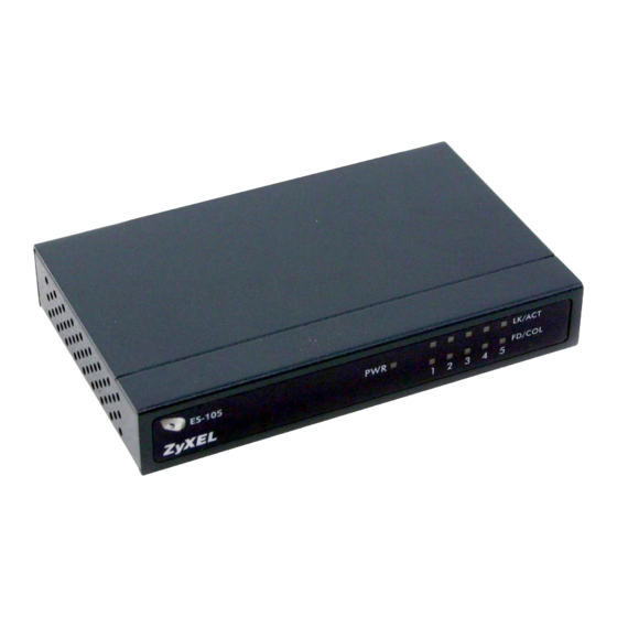
Page 5: Getting To Know Your Switch
Getting to Know Your Switch Introduction The switch is a multi-port switch that can be used to build high- performance switched networks. The switch is a store-and-forward device that offers low latency for high-speed networking. The switch is designed for SOHO (Small Office Home Office) businesses. Standalone Workgroup Application The switch can be used as a standalone switch to which computers, servers and print server are directly connected to form a small... -
Page 6: Hardware Description And Installation
Hardware Description and Installation The switch is suitable for an office environment where it can be placed on a desktop. Desktop Installation Step 1. Make sure the switch is clean and dry. Step 2. Set the switch on a smooth, leveled and sturdy flat space strong enough to support the weight of the switch and the connected cables. -
Page 7: Auto-Negotiating Ports
Figure 3 Rear Panel of the ES-108 RJ-45 Auto-negotiating Ports Your switch comes with 5 or 8 10Base-T/100Base-TX RJ-45 ports depending on the model of your switch. The auto-negotiation feature allows the switch to detect the speed of incoming transmission and adjust appropriately without manual intervention. -
Page 8: Power Port
Make sure the cable length between connections does not exceed 100 meters (328 Power Port Use the supplied power adapter to connect your switch to a power source. Refer to the label on the power adapter for more information. Front Panel LEDs The LED indicators give real-time information about the status of the switch. - Page 9 Table 2 The Front Panel LED Descriptions COLOR STATUS Green LK/ACT Green Blinking The port is receiving or transmitting data. FD/COL Orange On Blinking Packet collision occurred on this port. DESCRIPTION The switch is on and receiving power. The switch is not receiving power. The port is connected to an Ethernet network.
-
Page 10: Troubleshooting
Troubleshooting Troubleshoot the switch using the LEDs to detect problems. Power LED The PWR LED on the front panel does not light up. Table 3 Troubleshooting Power LED STEPS Check the connections from your switch to the power source. Make sure you are using the supplied power adapter and that you are using an appropriate power source. - Page 11 Table 4 Troubleshooting LK/ACT LED STEPS Verify that proper network cable type is used and its length does not exceed 100 meters. For more information on network cable types, see the Rear Panel Ethernet Cable Connections section. FD/COL LED The FD/COL LED blinks. Some collisions in the network are normal. If the FD/COL LED blinks continuously, proceed to the steps below.
-
Page 12: Troubleshooting Improper Network Cabling And Topology
Improper Network Cabling and Topology Improper network cabling or topology setup is a common cause of poor network performance or even network failure. Table 6 Troubleshooting Improper Network Cabling and DESCRIPTION Faulty cables Using faulty network cables may affect data rates and have an impact on your network performance.