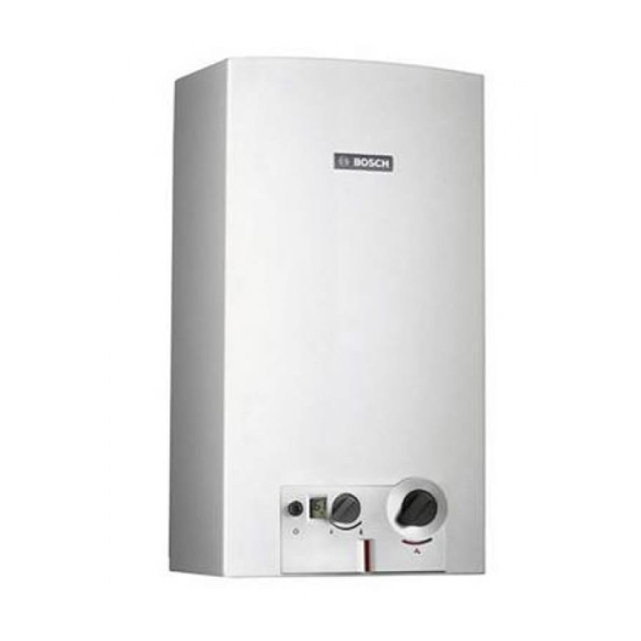
Bosch GWH 10-2 G Series Installation Manual And Operating Instructions
Hide thumbs
Also See for GWH 10-2 G Series:

Related Manuals for Bosch GWH 10-2 G Series


Summary of Contents for Bosch GWH 10-2 G Series
- Page 1 Installation Manual and Operating Instructions Gas Water Heaters GWH 10-2 G... | GWH 13-2 G... | GWH 16-2 G...
-
Page 2: Table Of Contents
Table of contents Table of contents Key to symbols and safety instructions ..3 Problems ........18 Explanation of symbols . -
Page 3: Key To Symbols And Safety Instructions
Key to symbols and safety instructions ▶ Do not operate any electrical Key to symbols and safety appliances or switches (on/off). instructions ▶ Extinguish other sources of ignition. Explanation of symbols ▶ Go to a different location and call the gas supplier or an authorised Warnings technician. - Page 4 Key to symbols and safety instructions Combustion air and surrounding air ▶ Handing these instructions to customer. ▶ To avoid corrosion, the combustion air and surrounding air must be free from harmful substances (e.g. THIS APPLIANCE IS NOT FOR USE AS A halogenated hydrocarbons which POOL OR SPA POOL HEATER.THIS contain chlorine and fluorine...
-
Page 5: Technical Characteristics And Dimensions
Technical Characteristics and Dimensions • Gas flow adjustment proportional to the water flow to Technical Characteristics and maintain a constant temperature. • Safety devices: Dimensions – Ionisation probe to check for accidental extinction of the burner flame General Description – Flue gas safety device which turns off the heater in The appliance has been AS/NZS 5263.1.2 tested. -
Page 6: Dimensions
Technical Characteristics and Dimensions Dimensions Fig. 1 [1] Front cover [8] Gas connection [2] Opening in rear panel for mounting on the wall [9] Connection collar for flue [3] Temperature/volume selector [10] Draught diverter [4] Gas adjustment [11] Copper Heat exchanger [5] Digital display [12] Burner [6] Switch/LED - Low water pressure indicator... -
Page 7: Functional Diagram Of The Heater
Technical Characteristics and Dimensions Functional diagram of the heater 6720608992-05.1V Fig. 2 Functional diagram [1] Pilot burner [17] Diaphragm [2] Ignition Electrode [18] Main gas valve [3] Ionisation probe [19] Maximum gas adjusting screw [4] Heat exchanger [20] Gas supply pipe [5] Main burner [21] Gas filter [6] Injector... -
Page 8: Electrical Diagram
Technical Characteristics and Dimensions Electrical diagram Fig. 3 Electrical diagram [1] Ignition electrode [7] Overtemperature switch [2] Ignition unit [8] Temperature sensor [3] Switch/LED - Low water pressure indicator [9] Pilot solenoid (Normally Closed) [4] Digital display [10] Diaphragm valve [5] Ionisation probe [11] Main Solenoid (Normally Open) [6] Flue gas safety device... -
Page 9: Technical Characteristics
Regulations Technical characteristics Technical characteristics Units GWH10 GWH13 GWH16 Gas Consumption Nominal Gas Consumption 100 (NG) 97 (LP gas) Supply pressure Natural gas H 1.13 1.13 1.13 LP gas 2.75 2.75 2.75 Number of injectors Water data Maximum permissible pressure 1000 1000 1000... -
Page 10: Important Information
Installation substances: halogenated hydrocarbons contained in This appliance should only be installed in solvents, paints, glues, hairsprays and various domestic applications where cold water temperature detergents. If necessary, take adequate measures. does not exceed 40 °C. • Install the appliance in accordance with the minimum installation clearances indicated in Fig.NOT DEFINED. -
Page 11: Heater Mounting
Installation Water connection DANGER: Make sure that all flue connections It is advisable to purge the water pipes before connection, are sealed. because the presence of dirt may reduce the flow and, in ▶ Fit the flue pipe with an approved flue cowl. extreme cases, cause a blockage. -
Page 12: Gas Connection
Installation Gas connection DANGER: If local regulations are not followed, a fire or explosion could result causing property damage, personal injury, or loss of life. Size gas supply as per AS5601. Incorrect gas pipe sizing will not be covered by the warranty. -
Page 13: Operating Instructions
Operating instructions Operating instructions Turning the heater on and off Open all water and gas isolation valves. Turning on Purge the pipes. ▶ Press the switch , position CAUTION: The front stainless steel panel in the burner and pilot burner area may reach high temperatures, with risk of burning in case of contact, and must not be removed. -
Page 14: Gas Adjustment
Operating instructions Gas adjustment Regulating the temperature to the minimum required value reduces energy consumption. Lower water temperature. Use less gas. CAUTION: The temperature on the display is not precise, always check before bathing children or elderly people. Draining the appliance There are two ways to drain the appliance if there is a risk of freezing. - Page 15 Operating instructions ▶ Drain all the water contained in the heater. Fig. 15 Draining [1] pressure relief screw 6 720 608 992 (2018/01)
-
Page 16: Commissioning
Commissioning Commissioning Inlet pressure adjustment ▶ Turn on the heater with the gas selector set to the left (maximum position). DANGER: The following procedures must only be performed by a qualified technician. Burner pressures have been adjusted in the factory, however adjustment may be required upon installation. -
Page 17: Maintenance
Remove the pipe and recommend the appliance be maintained on an annual basis. replace the flue pipe. These jobs can only be done by a Bosch authorised service * These procedures must be performed by a qualified installer/ agent. -
Page 18: Problems
Problems Problems Problem/cause/solution Assembly, maintenance and repairs must be performed by qualified technicians only. The following chart offers solutions to possible problems. Problem Cause Solution The heater does not ignite and digital Switch turned off. Check switch position. display is turned off. Slow and difficult ignition of the burner. -
Page 19: Environmental Protection
Bosch warranty would not apply. strictly observed. We use the best possible technology and materials, under economic considerations, to protect the Water quality table environment. - Page 20 1. Warranty of the hot water unit. Bosch offers, at its option, to repair or exchange this Bosch hot water unit or the relevant part listed in clause 2 below at no 4. Warranty conditions charge, if it becomes faulty or defective in manufacture or (a) Proof of purchase may be required.
- Page 21 Purpose. A customer can object at any time to the use of their personal information for the Purpose. Bosch will cease to use a customer's personal information accordingly if an objection is made.
- Page 22 Notes 6 720 608 992 (2018/01)
- Page 23 Notes 6 720 608 992 (2018/01)
- Page 24 6720608992 Australia Robert Bosch (Australia) Pty Ltd 1555 Centre Rd Clayton, VIC 3168 Phone 1300 30 70 37 Fax 1300 30 70 38 www.bosch.com.au/hotwater New Zealand Phone 0800 4 Bosch or 08 543 352 www.bosch.co.nz...