Table of Contents
Advertisement
Quick Links
Advertisement
Table of Contents

Related Manuals for Nikon T-RCP


Summary of Contents for Nikon T-RCP
- Page 1 M314E 04.7.CF.3(5/5) T-RCP Remote Control Pad Instructions...
-
Page 3: Table Of Contents
Contents Introduction .................................4 General Description ..........................4 Appearance of Remote Control Pad .....................5 Connection of Remote Control Pad and HUB Controller..............6 Startup and Shutdown...........................7 Screen Configuration ..........................8 (1) Summary.............................8 (2) Layout of OPERATION Screen ....................8 (3) Configuration of SETTING MENU Screens................9 (4) Configuration of MAINTENANCE MENU Screens ..............12 Preparations................................13 Connecting and Setting Electrical Components .................13... - Page 4 III Additional Functions............................31 Interlocking Objective and Condenser Module Selection ..............31 Interlock Filter Block and Excitation/Barrier Filters Selection .............32 Restricting Rotation of Revolving Nosepiece..................33 (1) Set Rotation Restriction ......................33 (2) Cancel Rotation Restriction ......................34 Performing Parfocal Corrections......................35 (1) Setting Focus Position ......................35 (2) Setting Parfocal Correction Mode.....................36 (3) Correcting Preset Focus Position .....................37 (4) Checking Preset Focus Position....................38...
- Page 5 VI Maintenance Menu .............................57 Indicating Program Version and Checksum..................57 Testing Electrical Component Operations ..................58 (1) All-Test Mode..........................58 (2) Individual Test Mode.........................60 Testing Hardware of Remote Control Pad ..................61 (1) Key Input Test...........................61 (2) LED ON/OFF Test ........................62 (3) LCD Indication Test ........................62 Initializing Focus Motion Potentiometer ....................63 Resetting Remote Control Pad Settings to Default Values ..............64 Resetting HUB Controller Settings to Default Values .................65...
-
Page 6: Introduction
Introduction 1 General Description Introduction General Description The remote control pad is connected to the HUB controller and used for remote control of the accessory electrical components of the ECLIPSE TE2000 series. The remote control pad enables control of the electrical components with key operations on the pad. The remote control pad also indicates a variety of information using the LED and displays on the LCD, such as electrical component positions and information on the attached optical members. -
Page 7: Appearance Of Remote Control Pad
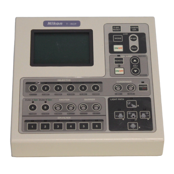
Introduction 2 Appearance of Remote Control Pad Appearance of Remote Control Pad Function when Functions when setting Parts OPERATION screen is indicated menu/maintenance menu is indicated OPERATION screen: Indicates Setting menu: Allows setting of electrical component positions and Liquid crystal display (LCD) various functions/parameters of the information on the attached optical electrical components. -
Page 8: Connection Of Remote Control Pad And Hub Controller
Introduction 3 Connection of Remote Control Pad and HUB Controller Connection of Remote Control Pad and HUB Controller Connect the HUB connection cable fixed to the remote control pad to REMOTE connector of the HUB controller as shown below. ub connection cable REMOTE connector [Connector panel of UB controller] [Rear panel of remote control pad]... -
Page 9: Startup And Shutdown
Introduction 4 Startup and Shutdown Startup and Shutdown Startup Turn ON power for the dia-illumination lamp. When using Uniblitz shutter, also turn ON power for the Uniblitz shutter controller. Turn ON the power to the HUB controller. Power is supplied to the remote control pad from the HUB controller. -
Page 10: Screen Configuration
Introduction 5 Screen Configuration Screen Configuration (1) Summary Power ON T-RCP REMOTE CONTROL PAD V1.00 MAINTENANCE MENU 1.Version 2.TEST1 3.TEST2 4.PAD Data Is MODE key 5.HUB Data 6.Control Data a.All Control Data pressed? b.Revoiving Nosepiece c.Condenser Cassette d.Light Path e.Filter Block f.Exciter Filter g.Barrier Filter h.AUX Filter MODE key SETTING MENU Objective MODE key Condenser Filter Exciter Barrier... -
Page 11: Configuration Of Setting Menu Screens
Introduction 5 Screen Configuration (3) Configuration of SETTING MENU Screens SETTING MENU OBJECTIVE Objective Series Mag. Esc. 1[P Fluor ] [DL 4x][-] Condenser 2[P Fluor ] [DL 10x][-] Filter 3[P Fluor ] [ELWD DM 20x][*] Exciter 4[P Fluor ] [ELWD DM 40x][*] Barrier... - Page 12 Introduction 5 Screen Configuration OBJECTIVE EDIT OBJECTIVE DATA Series Mag. Esc. 1[P Fluor ] [DL 4x][-] Location: [Other1] 2[P Fluor ] [DL 10x][-] Series : [――――――――――] 3[P Fluor ] [ELWD DM 20x][*] Mag. : [0 ]x 4[P Fluor ] [ELWD DM 40x][*] N.A. : [0 ] 5[P Fluor ] [ELWD DLL 60x][*] W.D. : [0 ] 6[P Fluor ] [DLL 100x][*] Type : [――――――――――] Edit Type N.A. W.D. Dry 0.13 17.10 CONDENSER EDIT CONDENSER DATA Name 1[BF ] Location: [Other1]...
- Page 13 Introduction 5 Screen Configuration MORE ROTATION STOPPER Rotation Stopper Current setting:OFF Focus Other Unit ON OFF Remote Control Pad Shutter Key Foot Switch MODE key Communication Delimiter FOCUS KNOB MODE [Coarse] FOCUS MODE [OFF] FOCUS POSITION SET SHIFT CLEAR OBJECTIVE Series...
-
Page 14: Configuration Of Maintenance Menu Screens
Introduction 5 Screen Configuration (4) Configuration of MAINTENANCE MENU Screens MAINTENANCE MENU VERSION 1.Version T-RCP REMOTE CONTROL PAD V1.00 Sum = 1234 2.TEST1 3.TEST2 4.PAD Data T-HUBC HUB CONTROLLER MAIN-cpu: V1.00 Sum = 5678 5.HUB Data SUB-cpu : V1.00 Sum = ABCD 6.Control Data a.All Control Data b.Revoiving Nosepiece c.Condenser Cassette d.Light Path e.Filter Block MODE key f.Exciter Filter g.Barrier Filter h.AUX filter TEST1 1/5 → ALL TEST... -
Page 15: Preparations
I Preparations 1 Connecting and Setting Electrical Components Preparations Connecting and Setting Electrical Components (1) Connecting Electrical Components to HUB Controller Make sure that the power switches for the microscope and the HUB controller are OFF. Connect the electrical components to be used to the HUB controller. Condenser module Revolving nosepiece changeover (Motorized... -
Page 16: Turning On The External Switch Of Dia-Illumination Lamp Power Supply
I Preparations 1 Connecting and Setting Electrical Components (2) Turning ON the EXTERNAL Switch of Dia-Illumination Lamp Power Supply XT RNAL switch [Rear panel of dia-illumination lamp power supply] Note: When the EXTERNAL switch is OFF, you cannot operate the dia-illumination lamp on the remote control pad. A 30-W power supply cannot be connected to the HUB controller. -
Page 17: Setting Attachment Information
I Preparations 2 Setting Attachment Information Setting Attachment Information Start up the remote control pad and set the optical members attached to the electrical components in use. The LCD indicates information for the set optical members. (1) Objective Set the information on objectives attached to the revolving nosepiece (motorized nosepiece). Press the MODE key, and the SETTING MENU screen will SETTING MENU... -
Page 18: Condenser Module
I Preparations 2 Setting Attachment Information Move to the next address of the revolving nosepiece using OBJECTIVE Series Mag. Esc. key or the key. Repeat steps 2 and 3 above. 1[P Fluor ] [DL 4x][―] 2[――――――――――] [―――――――――――――――][-] 3[――――――――――] [―――――――――――――――][-] 4[――――――――――] [―――――――――――――――][-] 5[――――――――――] [―――――――――――――――][-] 6[――――――――――] [―――――――――――――――][-] ... -
Page 19: Filter Block
I Preparations 2 Setting Attachment Information (3) Filter Block Set the information on filter blocks attached to the filter block changeover (motorized cassette holder). Press the MODE key, and the SETTING MENU screen will SETTING MENU Objective appear on the LCD. Condenser... -
Page 20: Excitation Filter
I Preparations 2 Setting Attachment Information (4) Excitation Filter Set the information on excitation filters attached to the excitation filter changeover (EX filter wheel). Press the MODE key, and the SETTING MENU screen will SETTING MENU Objective appear on the LCD. Condenser... -
Page 21: Barrier Filter
I Preparations 2 Setting Attachment Information (5) Barrier Filter Set the information on barrier filters attached to the barrier filter changeover (BA filter wheel). Press the MODE key, and the SETTING MENU screen will SETTING MENU Objective appear on the LCD. Condenser... -
Page 22: Setting Uniblitz Shutter Controller Connection
I Preparations 3 Setting Uniblitz Shutter Controller Connection Setting Uniblitz Shutter Controller Connection The HUB controller doesn’t automatically detect the Uniblitz shutter controller, unlike other electrical components. Be sure to set the connection of the Uniblitz shutter controller when using the Uniblitz shutter. Press the MODE key, and the SETTING MENU screen will SETTING MENU... -
Page 23: Setting Shutter Key Function
OPERATION screen. Note: If the Nikon motorized Epi-Fl attachment is not connected and the Uniblitz shutter controller connection is set to “OFF,” you cannot set the shutter key function. For details on the Uniblitz shutter controller connection setting, see section I-3 (Setting Uniblitz Shutter Controller Connection). -
Page 24: Setting Foot Switch Function
I Preparations 5 Setting Foot Switch Function Setting Foot Switch Function Allocate an electrical component to the foot switch. Press the MODE key, and the SETTING MENU screen will SETTING MENU Objective appear on the LCD. Condenser Filter Select “More” using the key or the key and then Exciter... -
Page 25: Indicating Z-Axis Position
I Preparations 6 Indicating Z-Axis Position Indicating Z-Axis Position Indication of the z-axis position is set to “OFF” by default. To indicate the z-axis position, edit the setting using the following procedure. (If TE2000-U or TE2000-S is used, the Z-Axis Position cannot be indicated.) Press the MODE key, and the SETTING MENU screen will SETTING MENU... -
Page 26: Basic Operation
II Basic Operation 1 Selecting Objective Basic Operation Selecting Objective Press the OBJECTIVE key to select an objective. Each OBJECTIVE key corresponds to one of the objectives; you can select an objective by simply pressing the key corresponding to the objective. Screen indication: The series name of the objective in the optical path is indicated. -
Page 27: Selecting Filter Block
II Basic Operation 2 Selecting Filter Block Selecting Filter Block Press the EPI-FILTER key to select a filter block. Each EPI-FILTER key corresponds to one of the filter blocks; you can select a filter block by simply pressing the key corresponding to the block. Screen indication: The name of the filter block in the optical path is indicated. -
Page 28: Selecting Optical Path
II Basic Operation 3 Selecting Optical Path Selecting Optical Path Press the LIGHT PATH key to select an optical path. Each LIGHT PATH key corresponds to one of the optical paths; you can select an optical path by simply pressing the key corresponding to the path. -
Page 29: Selecting Excitation Filter
II Basic Operation 5 Selecting Excitation Filter Selecting Excitation Filter Press the EXCITER key to turn the excitation filter changeover clockwise or counterclockwise to select an excitation filter. Screen indication: The currently selected address in the excitation filter changeover is indicated. The wavelength of the excitation filter in the optical path is indicated. -
Page 30: Inserting/Removing Analyzer
II Basic Operation 7 Inserting/Removing Analyzer Inserting/Removing Analyzer Press the ANALYZER IN/OUT key to insert and remove the analyzer. LED INDICATION: Green Orange Note: If the analyzer is not connected, the LED will not light up. Opening/Closing Shutter Press the SHUTTER A key to open and close the shutter allocated to SHUTTER A. -
Page 31: Turning Lamp On/Off
II Basic Operation 9 Operating Dia-Illumination Lamp (12V100W lamp only) (2) Turning Lamp ON/OFF You can turn the lamp ON or OFF as long as the LED of the DIA LAMP REMOTE key is green. Press the DIA LAMP ON/OFF key to turn the lamp ON or OFF. -
Page 32: Resetting Z-Axis Position To Zero
II Basic Operation 10 Resetting Z-Axis Position to Zero Resetting Z-Axis Position to Zero The current z-axis position can be indicated as 0.00 µm. Press the Z-AXI. RESET key to set the indication of the z-axis position to zero. Screen indication: The z-axis position is indicated. -
Page 33: Additional Functions
III Additional Functions 1 Interlocking Objective and Condenser Module Selection Additional Functions Interlocking Objective and Condenser Module Selection If combinations of objectives and condenser modules are set, then when an objective is selected, the condenser module corresponding to the objective is automatically selected. Press the MODE key, and the SETTING MENU screen will SETTING MENU... -
Page 34: Interlock Filter Block And Excitation/Barrier Filters Selection
III Additional Functions 2 Interlock Filter Block and Excitation/Barrier Filters Selection Interlock Filter Block and Excitation/Barrier Filters Selection If combinations of filter block and excitation/barrier filters are set, then when a filter block is selected, the excitation/barrier filters corresponding to the block are automatically selected. Press the MODE key, and the SETTING MENU screen will SETTING MENU... -
Page 35: Restricting Rotation Of Revolving Nosepiece
III Additional Functions 3 Restricting Rotation of Revolving Nosepiece Restricting Rotation of Revolving Nosepiece You can restrict the rotation of the revolving nosepiece with the OBJECTIVE key, so that the revolving nosepiece will not turn from the set z-axis position and upward. The upper limit setting is effective for all the addresses of the revolving nosepiece. -
Page 36: Cancel Rotation Restriction
III Additional Functions 3 Restricting Rotation of Revolving Nosepiece (2) Cancel Rotation Restriction Press the MODE key, and the SETTING MENU screen will SETTING MENU Objective appear on the LCD. Condenser Filter Select “More” using the key or the key and then Exciter... -
Page 37: Performing Parfocal Corrections
III Additional Functions 4 Performing Parfocal Corrections Performing Parfocal Corrections Presetting a focus position for each objective allows the parfocal correction function to compensate automatically for deviations in focus positions caused by switching objectives. Please read "(1) Setting Focus Position" and "(2) Setting Parfocal Correction Mode"... -
Page 38: Setting Parfocal Correction Mode
III Additional Functions 4 Performing Parfocal Corrections Select "SET" for "FOCUS POSITION" using the FOCUS KNOB MODE [Coarse] key and then press the [ ] key. FOCUS MODE [OFF] This sets the focus position for the 10x objective. FOCUS POSITION SET... -
Page 39: Correcting Preset Focus Position
III Additional Functions 4 Performing Parfocal Corrections (3) Correcting Preset Focus Position If changing specimens results in a change in focus positions, you can correct focus positions for all objectives with a single operation. Simply adjust focus and set the correct position for the 10x objective; this will correct differences in focus positions for all other objectives. -
Page 40: Checking Preset Focus Position
III Additional Functions 4 Performing Parfocal Corrections (4) Clearing Preset Focus Position Preset focus positions can be cleared. Press the MODE key, and the SETTING MENU screen will SETTING MENU Objective appear on the LCD. Condenser Filter Select “More” using the key or the key and then Exciter... -
Page 41: Other Operations
IV Other Operations 1 Operating LCD Backlight Other Operations Operating LCD Backlight (1) Turning Backlight ON/OFF Press the LCD ON/OFF key to turn the backlight ON or OFF. LED INDICATION: Green Orange (2) Adjusting Brightness of Backlight Press the DIA Bright/Dark key to adjust the brightness of the backlight. -
Page 42: Adjusting Lcd Contrast
IV Other Operations 2 Adjusting LCD Contrast Adjusting LCD Contrast To adjust the contrast of the LCD, first remove the rear panel of the remote control pad, then set DIP switch No. 9 to ON. Press the DIA Bright/Dark key to adjust the contrast, just like adjusting backlight brightness. -
Page 43: Operation And Indication Functions
V Operation and Indication Functions 1 Setting Functions for the Fine Focus Knob Operation and Indication Functions Setting Functions for the Fine Focus Knob (1) Changing Operation Mode of Fine Focus Knob Change the operation mode of the fine focus knob used for the focusing mechanism. [Operation mode list] Coarse = 100 µm/rev. -
Page 44: Adjusting Travel Distance For Fine Mode
V Operation and Indication Functions 1 Setting Functions for the Fine Focus Knob Press the MODE key to end the setting and to return to the OPERATION screen. (2) Adjusting Travel Distance for Fine Mode To facilitate focusing with a high-magnification lens, you can adjust travel distance in Fine mode in five steps as desired, as shown in the table below. - Page 45 V Operation and Indication Functions 1 Setting Functions for the Fine Focus Knob Set travel distance in Fine mode using one of the CONDENSER keys. Since the travel distance adjusted is reflected immediately after you press a CONDENSER key, you can check the amount of movement while making adjustments.
-
Page 46: Setting Indication On Operation Screen
V Operation and Indication Functions 2 Setting Indication on Operation Screen Setting Indication on Operation Screen The OPERATION screen indicates a variety of information, such as the current electrical component positions and information on the currently attached optical members. This function turns indication of such information ON or OFF. Press the MODE key, and the SETTING MENU screen will SETTING MENU... -
Page 47: Setting Buzzer On/Off
V Operation and Indication Functions 3 Setting Buzzer ON/OFF Setting Buzzer ON/OFF Turn ON or OFF the buzzer confirmation that sounds when a key is pressed. Press the MODE key, and the SETTING MENU screen will SETTING MENU Objective appear on the LCD. Condenser... -
Page 48: Setting Remote Control On/Off
V Operation and Indication Functions 4 Setting Remote Control ON/OFF Setting Remote Control ON/OFF Turn remote-control operation of the electrical components using the remote control pad ON or OFF. Press the MODE key, and the SETTING MENU screen will SETTING MENU Objective... -
Page 49: Turning On/Off Led With Lcd On/Off Key
V Operation and Indication Functions 5 Turning ON/OFF LED with LCD ON/OFF Key Turning ON/OFF LED with LCD ON/OFF Key Enable the LCD ON/OFF key to turn the LED ON or OFF. Press the MODE key, and the SETTING MENU screen will SETTING MENU... -
Page 50: Setting Communications Delimiter Of External Device
V Operation and Indication Functions 6 Setting Communications Delimiter of External Device Setting Communications Delimiter of External Device Set the delimiter for communications between the HUB controller and an external device. [Delimiter] CR is selected by default. Press the MODE key, and the SETTING MENU screen will SETTING MENU... -
Page 51: Registering Data For Optical Members
V Operation and Indication Functions 7 Registering Data for Optical Members Registering Data for Optical Members (1) Objective You can register optional data for up to nine objectives. If an attached objective is not listed in the presets, register the objective. Press the MODE key, and the SETTING MENU screen will SETTING MENU... - Page 52 V Operation and Indication Functions 7 Registering Data for Optical Members Move the cursor to “W.D.” using the key or the key. EDIT OBJECTIVE DATA Location: [Other1] Using the numerical keys and the key or the key, Series : [Other ] Mag. : [10 ]x enter the working distance within the range between 0.01 N.A. :...
-
Page 53: Condenser Module
V Operation and Indication Functions 7 Registering Data for Optical Members (2) Condenser Module You can register optional data for up to nine condenser modules. If an attached condenser module is not listed in the presets, register the condenser module. Press the MODE key, and the SETTING MENU screen will SETTING MENU... -
Page 54: Filter Block
V Operation and Indication Functions 7 Registering Data for Optical Members (3) Filter Block You can register optional data for up to nine filter blocks. If an attached filter block is not listed in the presets, register the filter block. Press the MODE key, and the SETTING MENU screen will SETTING MENU... - Page 55 V Operation and Indication Functions 7 Registering Data for Optical Members Move the cursor to “BA” using the key or the key. EDIT FILTER DATA Location: [Other1] Select a barrier filter for the filter block using the PREV or Name : [ABC ] NEXT key. If the barrier filter is not listed in the presets, EX :...
-
Page 56: Dichroic Mirror
V Operation and Indication Functions 7 Registering Data for Optical Members (4) Dichroic Mirror You can register optional data for up to nine dichroic mirrors. If an attached dichroic mirror is not listed in the presets, register the dichroic mirror. Select “Edit”... -
Page 57: Excitation Filter
V Operation and Indication Functions 7 Registering Data for Optical Members (5) Excitation Filter You can register optional data for up to nine excitation filters. If an attached excitation filter is not listed in the presets, register the excitation filter. Press the MODE key, and the SETTING MENU screen will SETTING MENU... -
Page 58: Barrier Filter
V Operation and Indication Functions 7 Registering Data for Optical Members (6) Barrier Filter You can register optional data for up to nine barrier filters. If an attached barrier filter is not listed in the presets, register the barrier filter. Press the MODE key, and the SETTING MENU screen will SETTING MENU... -
Page 59: Maintenance Menu
VI Maintenance Menu 1 Indicating Program Version and Checksum Maintenance Menu Indicating Program Version and Checksum Indicate the program version of the remote control pad and the HUB controller and the checksum on the LCD. Turn on the power to the HUB controller while holding MAINTENANCE MENU... -
Page 60: Testing Electrical Component Operations
VI Maintenance Menu 2 Testing Electrical Component Operations Testing Electrical Component Operations Test the operations of the electrical components connected to the HUB controller. There are two test modes. All-test mode: Test all the electrical components connected. Individual test mode: Select a component and test the component. - Page 61 VI Maintenance Menu 2 Testing Electrical Component Operations → After the test of one component is completed, “ ” moves TEST1 2/5 EPI-FILTER to the next component and the test of the component will 1 [OK] 2 [OK] begin. 3 [OK] 4 [OK] 5 [OK] The components not connected to the HUB controller will 6 [OK]...
-
Page 62: Individual Test Mode
VI Maintenance Menu 2 Testing Electrical Component Operations (2) Individual Test Mode Turn on the power to the HUB controller while holding MAINTENANCE MENU down the MODE key. 1.Version 2.TEST1 3.TEST2 4.PAD Data After the MAINTENANCE MENU screen appears, release 5.HUB Data 6.Control Data the MODE key. -
Page 63: Testing Hardware Of Remote Control Pad
VI Maintenance Menu 3 Testing Hardware of Remote Control Pad Testing Hardware of Remote Control Pad The following tests are available to evaluate the hardware of the remote control pad. Key input test Checks to see if the input of each key is read correctly LED ON/OFF test Checks to see if all the LEDs are controlled correctly LCD indication test... -
Page 64: Led On/Off Test
VI Maintenance Menu 3 Testing Hardware of Remote Control Pad (2) LED ON/OFF Test Turn on the power to the HUB controller while holding MAINTENANCE MENU down the MODE key. 1.Version 2.TEST1 3.TEST2 4.PAD Data After the MAINTENANCE MENU screen appears, release 5.HUB Data... -
Page 65: Initializing Focus Motion Potentiometer
VI Maintenance Menu 4 Initializing Focus Motion Potentiometer Initializing Focus Motion Potentiometer The potentiometer can be initialized at each reference point to detect absolute position of the focusing mechanism. Use this function after changing the combination of the microscope and HUB controller. Initialization takes about 3 minutes to be completed. -
Page 66: Resetting Remote Control Pad Settings To Default Values
VI Maintenance Menu 5 Resetting Remote Control Pad Settings to Default Values Resetting Remote Control Pad Settings to Default Values Use this function to reset the settings stored in the memory of the remote control pad back to the default values (See Table 1). -
Page 67: Resetting Hub Controller Settings To Default Values
VI Maintenance Menu 6 Resetting HUB Controller Settings to Default Values Resetting HUB Controller Settings to Default Values Use this function to reset the data stored in the memory of the HUB controller back to the default values. For example, the memory stores information on the attached objectives, registered optional data of optical members, and information on the interlocking of the revolving nosepiece and the condenser module changeover (See Table Turn on the power to the HUB controller while holding MAINTENANCE MENU... -
Page 68: Reset Control Data To Default Values
VI Maintenance Menu 7 Reset Control Data to Default Values Reset Control Data to Default Values Use this function to reset the control data stored in the memory of the HUB controller to their default values. Use this function when an electrical component doesn’t work properly or has been replaced with a new component. The control data of the electrical components are initialized either in batches or individually. -
Page 69: Revolving Nosepiece
VI Maintenance Menu 7 Reset Control Data to Default Values When the initialization is completed, “Complete!” appears CONTROL DATA and remains displayed for about one second. The Initialize all control data ? MAINTENANCE MENU screen then appears. Yes No ・・・・・・・・・・・・・・・・・・・・・・・・・・・・・・・・ Complete! MAINTENANCE MENU 1.Version 2.TEST1 3.TEST2... -
Page 70: Condenser Module
VI Maintenance Menu 7 Reset Control Data to Default Values (3) Condenser Module Turn on the power to the HUB controller while holding MAINTENANCE MENU down the MODE key. 1.Version 2.TEST1 3.TEST2 4.PAD Data After the MAINTENANCE MENU screen appears, release 5.HUB Data 6.Control Data... -
Page 71: Optical Path
VI Maintenance Menu 7 Reset Control Data to Default Values (4) Optical Path Turn on the power to the HUB controller while holding MAINTENANCE MENU down the MODE key. 1.Version 2.TEST1 3.TEST2 4.PAD Data After the MAINTENANCE MENU screen appears, release 5.HUB Data 6.Control Data... -
Page 72: Filter Block
VI Maintenance Menu 7 Reset Control Data to Default Values (5) Filter Block Turn on the power to the HUB controller while holding MAINTENANCE MENU down the MODE key. 1.Version 2.TEST1 3.TEST2 4.PAD Data After the MAINTENANCE MENU screen appears, release 5.HUB Data 6.Control Data... -
Page 73: Excitation Filter
VI Maintenance Menu 7 Reset Control Data to Default Values (6) Excitation Filter Turn on the power to the HUB controller while holding MAINTENANCE MENU down the MODE key. 1.Version 2.TEST1 3.TEST2 4.PAD Data After the MAINTENANCE MENU screen appears, release 5.HUB Data 6.Control Data... -
Page 74: Barrier Filter
VI Maintenance Menu 7 Reset Control Data to Default Values (7) Barrier Filter Turn on the power to the HUB controller while holding MAINTENANCE MENU down the MODE key. 1.Version 2.TEST1 3.TEST2 4.PAD Data After the MAINTENANCE MENU screen appears, release 5.HUB Data 6.Control Data... -
Page 75: Auxiliary Filter
VI Maintenance Menu 7 Reset Control Data to Default Values (8) Auxiliary Filter Turn on the power to the HUB controller while holding MAINTENANCE MENU down the MODE key. 1.Version 2.TEST1 3.TEST2 4.PAD Data After the MAINTENANCE MENU screen appears, release 5.HUB Data 6.Control Data... -
Page 76: Troubleshooting
VII Troubleshooting 1 Remote control pad doesn’t start up. (Title screen appears, and the screen freezes.) Troubleshooting Remote control pad doesn’t start up. (TITLE screen appears, and the screen freezes.) Cause Action Turn OFF the power to the HUB controller. Disconnect the remote control pad from the HUB controller and connect it again. -
Page 77: Voltage Of Dia-Illumination Lamp Cannot Be Adjusted
VII Troubleshooting 5 Voltage of dia-illumination lamp cannot be adjusted. Voltage of dia-illumination lamp cannot be adjusted. Cause Action Turn OFF the power of the HUB controller. Disconnect the dia-illumination lamp power supply from the HUB controller and connect it The dia-illumination lamp power supply is not again. -
Page 78: Excitation Filter Information Is Not Indicated
VII Troubleshooting 10 Excitation filter information is not indicated. Excitation filter information is not indicated. Cause Action Turn OFF the power to the HUB controller. Disconnect the excitation The excitation filter changeover is not connected to filter changeover from the HUB controller and connect it again. the HUB controller correctly.