Table of Contents
Advertisement
Quick Links
Advertisement
Table of Contents

Related Manuals for NASA EML-2

Summary of Contents for NASA EML-2
- Page 1 DESIGNED AND MANUFACTURED IN ENGLAND EML-2 ELECTRO- MAGNETIC RoHS 2002/95/EC...
- Page 2 TARGET EM DISPLAY DRILL TEMPLATE...
-
Page 3: How It Works
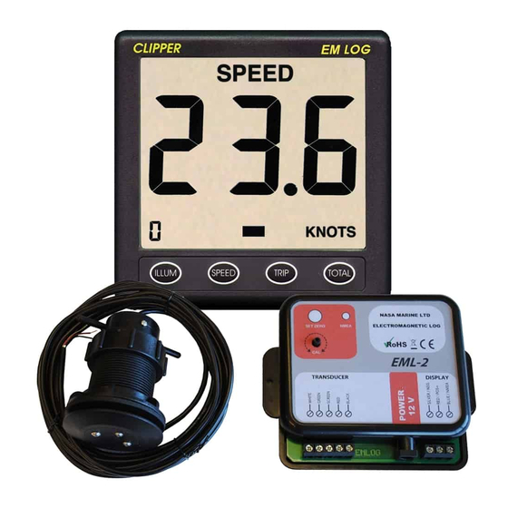
INTRODUCTION. The EML-2 log consists of a through hull sensor and an interface box which, when correctly installed, outputs boat speed through the water, trip distance and total distance. The unit is factory set but has the facility for final in situ calibration. -
Page 4: Installing The Sensor
INSTALLING THE SENSOR. IMPORTANT: Read and fully understand the installation instructions and only proceed if you possess the required skills and correct tools. WARNING: Always wear safety glasses and a dust mask when installing to avoid personal injury. WARNING: Immediately check for leaks when the boat is put back in the water. WARNING: The O-rings must be intact and, the lower one, properly lubricated to make a watertight seal. - Page 5 Fig 1 Carefully remove all surplus sealant from the inside and outside of the hull and leave until the sealant has cured. It is recommended that the area around the skin fitting is thoroughly cleaned and the whole assembly be fibre glassed into the hull as shown in fig 2.
- Page 6 Before pushing the sensor into the skin fitting, ensure the lower O-ring is liberally lubricated with silicone grease. Push the sensor into the skin fitting with the arrow pointing forward and hand tighten the securing ring. INSTALLING THE INTERFACE BOX. The interface box is not waterproof and should be mounted in a permanently dry location.
- Page 7 CONNECTING TO THE NASA Marine Clipper EM or Target EM LOG displays. The Clipper or Target EM log display can be connected directly to the interface box as shown in fig 4. Alternatively, if a longer length of cable is required, a three-way cable and terminal block is supplied and is connected as in fig 5.
- Page 8 It is good practice to run the cables vertically downwards from the unit. Doing so prevents any moisture that may collect on the cables from running back into the unit. CALIBRATING THE EML-2. First the set damping level to zero. With the boat at rest in still water, a small (usually less than 2Kts) steady error may occur.
-
Page 9: Cleaning The Sensor
An old toothbrush can be used to scrub the surface. If the electrodes show any signs of damage they can be removed using a 2mm Allen key. Spares are available from NASA Marine. Take care, when replacing the electrodes, not to get water in the threads. - Page 10 NOTES...
-
Page 12: Limited Warranty
Prior to unpacking this instrument read and fully understand the installation instructions. Only proceed with the installation if you are competent to do so. Nasa Marine Ltd. will not accept any responsibility for injury or damage caused by, during or as a result of the installation of this product.