Table of Contents

Related Manuals for NAL A3LA-R


Summary of Contents for NAL A3LA-R
- Page 1 TN2013-12-V1.1 GENERAL DESCRIPTION OF MODEL A3LA-R Version 1.1 April 8 , 2013 Copyright © 2013 by NAL Research Corporation 9385 Discovery Boulevard Manassas, Virginia 20109 USA Phone: 703-392-1136 x203 E-mail: contact@nalresearch.com...
- Page 2 Iridium satellite services to the fullest extent these damages may be disclaimed by law and whether advised of the possibilities of such damages. NAL Research is not liable for any claim made by a third party or made by you for a third party.
-
Page 3: Table Of Contents
APPENDIX D: INFORMATIVE EXAMPLES ................APPENDIX E: POWER CONSUMPTION .................. APPENDIX F: DESCRIPTION OF THE IRIDIUM NETWORK ............APPENDIX G: STANDARDS COMPLIANCE ................APPENDIX H: MIL-STD-810G CERTIFICATION ............... APPENDIX I: EXPORT COMPLIANCE INFORMATION ..............APPENDIX J: MECHANICAL DRAWINGS ................NAL Research Corporation (TN2013-12-V1.1) -
Page 4: Glossary
Right Hand Circular Polarization RUDICS Router-Based Unrestricted Digital Internetworking Connectivity Solution Short Burst Data Subscriber Identity Module Sub-Miniature Version A Short Message Service Time Domain Duplex TDMA Time Division Multiple Access VSWR Voltage Standing Wave Ratio NAL Research Corporation (TN2013-12-V1.1) -
Page 5: Purpose
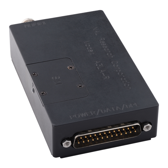
A3LA-R is functionally compatible with models 9522, 9522A, A3LA-D, 9522B and A3LA-X. It is approximately 60% smaller in volume and 50% lighter than the 9522B. Model A3LA-R-MIL is an A3LA-R that has been certified to MIL-STD-810G standards and IP67 rating. - Page 6 Average Data Call Current: ~350mA @ 5.0VDC (peak of 2A) NOTE: The power requirements apply to DC power measured at the A3LA-R multi-interface connector input. The average data call current may vary depending on the field-of-view between the modem antenna and the Iridium satellite.
-
Page 7: Multi-Interface Connector
A3LA-R’s modem functionality through standard AT and extended sets of AT commands. These commands are defined in Appendix A. The A3LA-R will automatically adjust to the DTE baud rate and override the +IPR setting when dissimilar. Autobaud will occur on the following characters ‘a’, ‘A’ or CR (carriage return). -
Page 8: Rs232 Data Interface (3-Wire Configuration)
A3LA-R to malfunction during a data call, an SMS session or an SBD session. Power reset by the A3LA-R during a call is an indicative of the DC power source unable to sustain voltage above 4.0V at peak current demand. Appendix E provides the electrical power profile of the A3LA-R. -
Page 9: Power On/Off Control
With the A3LA-R held in the position shown in Figure 2 (DB25 connector to the left), the A3LA-R is set for 4.0V to +5.5V when the red jumper is on the middle and left pins and is set for +5.0V to +32V when the jumper is on the middle and right pins. Each pin is also labeled with 5V and 32V to the left and right pins, respectively. -
Page 10: Audio Interface
The A3LA-R supports both digital and analog audio I/O. The digital audio is in PCM format. In such format, digital audio cannot travel far (less than one foot); this is why the analog is chosen for the A3LA-R audio handset. The analog audio input is a single-ended, unbalanced input with a minimum impedance of 10k... -
Page 11: Sim Card Interface
Figure 4. Location of the SIM reader. 6.0 LED DISPLAY The A3LA-R has a status LED depicted as P for power indicator (see Figure 5). It offers users a quick visual check to ensure power is provided to the modem. -
Page 12: Configuration Settings
R. In command mode, flow control has no effect, with the RTS input ignored and the CTS output driven ON (low). When in SBD data mode, the A3LA-R is transferring binary or text SBD message data to or from the DTE. -
Page 13: Mounting Recommendations
SBD AT commands; the DTE has no other control over the mode. 9.0 MOUNTING RECOMMENDATIONS The A3LA-R has four features on its bottom surface that can aid in its mounting (see Appendix I). These four features are pre-drilled at a minimum depth of 0.25 inch to accept 6-32 thread type. -
Page 14: Appendix A: At Interface
Some basic commands listed in this document are marked with “No action, compatibility only”. In these cases, the basic command is accepted in the same fashion as is with other modems, but has no effect on the operation of the A3LA-R, since it has no meaning in the Iridium environment. - Page 15 A.5 Command Entry An AT command is a string of characters sent by the DTE to the A3LA-R while it is in command mode. A command string has a prefix, a body, and a terminator. The prefix consists of the ASCII characters AT or at.
- Page 16 Result codes can be represented by text if the A3LA-R is in verbose mode or with numbers if in numeric mode. The command ATVn informs the A3LA-R whether to respond in verbose or numeric mode. Further note that responses can be suppressed by setting the command ATQn to ATQ1.
- Page 17 A.7 Hardware Failure Reporting If the A3LA-R detects a hardware problem during initialization, it may be unable to function correctly. The A3LA-R notifies the DTE of this situation by issuing an unsolicited result code at the end of initialization: HARDWARE FAILURE: <subsys>,<error>...
- Page 18 A.8.7 Vn – Verbose Mode Set the response format of the A3LA-R, which may be either numeric or textual. Numeric responses Textual responses (default) A.8.8 Wn – Error Correction Message Control Set the format of the CONNECT messages. Upon connection, the A3LA-R reports the DTE speed (default)
- Page 19 (default). If DTR transitions from ON to OFF during either in-call command mode or in-call data mode, the call will drop to on-hook command mode and the A3LA-R will reset to AT command profile 0.
- Page 20 Select profile 1 A.8.20 \Kn – Control Break Control the response of the A3LA-R to a break received from the DTE or the remote modem according to the parameter specified. The response is different in three separate states: When a break is received from DTE when A3LA-R is in data transfer mode:...
- Page 21 List the supported <speed>, <name>, <ce>. Response is in the form: +CBST: (supported <speed>s),(supported <name>s),(supported <ce>s) A.8.24 +CGMI – Manufacturer Identification Exec Command: +CGMI Query A3LA-R RF board manufacturer. A.8.25 +CGMM – Model Identification Exec Command: +CGMM Query A3LA-R RF board model.
- Page 22 A3LA-R RF board-adaptor link reserved operation not allowed operation not supported PH-SIM PIN required PH-FSIM PIN required PH-FSIM PUK required SIM not inserted SIM PIN required SIM PUK required SIM failure SIM busy SIM wrong incorrect password SIM PIN2 required...
- Page 23 Set the service reporting level. <mode> takes the following values: Disable reporting (default) Enable reporting If reporting is enabled, the intermediate result code +CR: <serv> is returned by the A3LA-R. <serv> can have one of the following values: ASYNC asynchronous transparent...
- Page 24 Do not disconnect if V.42bis is not negotiated by the A3LA-R as specified in <direction> (default) Disconnect if V.42bis is not negotiated by the A3LA-R as specified in <direction> <max_dict> can take on the following values: 512 to 2048. Default is 512.
- Page 25 A.8.33 +CEER – Extended Error Report Exec Command: +CEER Execution command causes the A3LA-R to return information text <report> which offers the user an extended report of the reason of the failure in the last unsuccessful call setup (originating or answering) or the reason for last call release. The response is in the form: +CEER: <report>...
- Page 26 PDU mode parameter invalid text mode parameter no SIM SIM PIN required PH-SIM PIN required SIM failure SIM busy SIM wrong memory failure invalid memory index memory full SM-SC address unknown no network service network timeout unknown error NAL Research Corporation (TN2013-12-V1.1)
- Page 27 A.8.36 +CMGF – SMS Message Format Set Command: +CMGF=[<mode>] Set command tells the A3LA-R, which input and output format of messages to use. <mode> indicates the format of messages used with send, list, read and write commands and unsolicited result codes resulting from received messages. Mode can be either PDU mode (entire TP data units used) or text mode (headers and body of the messages given as separate parameters).
- Page 28 Test command gives a list of all status values supported by the A3LA-R. Response is in the form: +CMGL: (list of supported <stat>s) A.8.38 +CMGR – Read SMS Message Exec Command: +CMGR=<index> Execution command returns the SMS message with location value <index> from message storage <mem1>...
- Page 29 DTE when DTE is active, e.g. DTR signal is ON. Valid values for <mode> are: Buffer unsolicited result codes in the A3LA-R. If result code buffer is full, older indications are discarded and replaced with the new received indications. (default) Discard indication and reject new received message unsolicited result codes when A3LA-R-DTE link is reserved (e.g.
- Page 30 <bm>s),(list of supported <ds>s),(list of supported <bfr>s) A.8.43 +COPS – Operator Select Set Command: +COPS=[<mode>[,<format>[,<oper>]]] Set command forces an attempt to manually register the A3LA-R to the network. Only IRIDIUM as <oper> is supported. Valid values for the parameters are outlined below.
- Page 31 “IRIDIUM” and the numeric format is “90103”. These are the only values accepted. Note that setting the <mode> to manual does not disable automatic registration of the A3LA-R to the network. It just forces a manual registration procedure when entered.
- Page 32 <storage> takes the following values: SIM fixed dialing phonebook Last ten calls dialed phonebook A3LA-R phonebook combined A3LA-R and SIM phonebook (default) SIM phonebook Read Command: +CPBS? Read command returns currently selected memory, the number of used locations and total number of locations in the memory.
- Page 33 A.8.48 +CPIN – Enter PIN Set Command: +CPIN=<pin>[,<newpin>] Set command sends to the A3LA-R a password which is necessary before it can be operated (SIM Card PIN Code, SIM PUK, etc.). If no password request is pending, no action is taken by the A3LA-R.
- Page 34 <mem2> is the memory to which writing and sending operations are made; <mem3> is the memory to which received SMS messages are to be stored. If a chosen storage is not appropriate for the A3LA-R, final result code +CMS ERROR: <cms_err> is returned.
- Page 35 Read command returns the status of result code presentation and an integer <stat> which shows the network registration status of the A3LA-R. Location information elements <lac> and <ci> are returned only when <n>=2 and A3LA-R is registered in the network. Response is in the form: +CREG: <n>,<stat>[,<lac>,<ci>]...
- Page 36 A.8.53 +CSCS – Select TE Character Set Set Command: +CSCS=[<chset>] Set command informs the A3LA-R which character set <chset> is used by the DTE. Only the IRA character set is currently supported. <chset> should be of string type enclosed by ““; for example, “IRA”.
- Page 37 Answer immediately. This causes the A3LA-R to answer the incoming data or voice call. A.8.62 D – Dial Dial a data or voice call number. The dial command causes the A3LA-R to enter originate mode and act as an auto dialer for connection to other modems or voice lines. The usual format is ATDnx..x where n is a Dial Modifier and x is a number.
- Page 38 Enable auto-answer after n rings A.8.65 Xn – Extended Result Codes Select the response set to be used by the A3LA-R when informing the DTE of the results of a command or data or voice call. OK, CONNECT, RING, NO CARRIER, NO ANSWER and ERROR...
- Page 39 CONNECT response is used to inform of a data call connection; OK response is used to inform of a voice call connection (only for A3LA-R/RM/RGS). As X0 plus CONNECT x, where x is the DTE speed CONNECT x response is used for data calls only.
- Page 40 <mode> takes the following values: Disable extended format (default) Enable extended format If extended format is enabled, the unsolicited result code +CRING: <type> is returned by the A3LA-R instead of RING, where <type> can be one of the following: ASYNC asynchronous transparent SYNC...
- Page 41 Set Command: +CCLK=[<time>] Sets the real-time clock of the A3LA-R. If setting fails, ERROR is returned. <time>: string type value; format is “yy/MM/dd,hh:mm:sszz”, where characters indicate year two last digits), month, day, hour, minutes, seconds and time zone. There is no blank space between the two double quotes.
- Page 42 –MSSTM: <system_time> <system_time> can take one of the following forms: no network service The A3LA-R has not yet received system time from the network. XXXXXXX Where XXXXXXXX is the current Iridium system time available from the network. The system time as received through the Iridium Air Interface, is a 32 bit integer count of the number of 90 millisecond intervals that have elapsed since the epoch.
- Page 43 Iridium system time from the network. Once the time is received, the A3LA-R uses its internal clock to increment the counter. In addition, at least every 8 hours, or on location update or other event that requires re-registration, the A3LA-R will obtain a new system time from the network.
- Page 44 A.8.77 +CLCC – Request Current Call Status Exec Command: +CLCC Returns the current call status of the A3LA-R. The response is a comma separated list of call states. The number of call states in the response depends on the number of active call instances e.g.
- Page 45 <ver> specifies the desired IRLP version and can take the following values: Default IRLP version (N0) <k1> represents the maximum number of sequentially numbered I frames that may be outstanding at any given time at downlink direction (IWF->A3LA-R) and can take the following values: 1-105. Default is 105.
- Page 46 <k2> represents the maximum number of sequentially numbered I frames that may be outstanding at any given time at uplink direction (A3LA-R->IWF) and can take the following values: 1-105. Default is 105. <t1> is used to supervise the acknowledgment of transmitted unnumbered frames. The values...
- Page 47 1-255 (in 1000-ms unit). Default is 15 for 15000 ms. <dtl> denotes the delay tolerance in the link delay difference and can take the following values: 1-100 (in 1% unit). Default is 10%. Read Command: +WDLDM? NAL Research Corporation (TN2013-12-V1.1)
- Page 48 Once the command is entered, the A3LA-R will indicate to the DTE that it is prepared to receive the message by sending the ASCII encoded string “READY<CR><LF>” (hex 52 45 41 44 59 0D 0A) to the DTE.
- Page 49 This command is used to transfer a text SBD message from the single mobile terminated buffer in the A3LA-R to the DTE. This command is similar to +SBDRB but does not provide a length indicator or checksum. The intent of this command is to provide a human friendly interface to SBD for demonstrations and application development.
- Page 50 The mobile terminated buffer will be cleared when an SBD session is initiated. Sending a message from the A3LA-R to the ESS does not clear the mobile originated buffer. Reading a message from the A3LA-R does not clear the mobile terminated buffer.
- Page 51 This command will transfer the contents of the mobile originated buffer to the mobile terminated buffer. Developers of DTE can use this command to test reading and writing to the A3LA-R without actually initiating SBD sessions with the ESS. Command Response:...
- Page 52 Network service availability is equivalent to a signal strength greater than 0. The service availability indicator provides a way for the DTE to wait until the A3LA-R can start an SBD session without receiving continual notifications of changes in signal strength.
- Page 53 No SBD ring alert received SBD ring alert received Note: It is valid for the A3LA-R/RM/RGS to receive a telephony ring alert and an SBD ring alert at the same time. Assertion of the RI signal indicates only the presence of an alert; this command may be used to determine the type(s) of ring alert.
- Page 54 If the A3LA-R has no SIM, is awaiting a SIM PIN entry, has an invalid SIM, or has otherwise not proceeded to successful registration, the delay in response may exceed the 50 second timeout limit. Under such condition, an ERROR response will be received. To avoid a delayed response due to registration problems, issue the +CREG command to verify registration prior to entering the +CSQ command to obtain signal strength.
- Page 55 A.8.100 +CLIP – Calling Line Identification Presentation Exec Command: +CLIP=<n> Note: While this command is implemented in the A3LA-R, it may not yet be supported in the Iridium network. Stand by for an Iridium Technical Bulletin announcing network support for this feature.
- Page 56 A.8.101 +CLIR – Calling Line Identification Restriction Exec Command: +CLIR=<n> Note: While this command is implemented in the A3LA-R, it may not yet be supported in the Iridium network. Stand by for an Iridium Technical Bulletin announcing network support for this feature.
- Page 57 Alternatively, the text message may be entered separately: Upon entering the command “AT+SBDWT”, the A3LA-R will indicate to the DTE that it is prepared to receive the message by sending the string “READY<CR><LF>” (hex 52 45 41 44 59 0D 0A) to the DTE ...
- Page 58 This instructs the GSS to disable (detach) SBD ring alerts for the calling A3LA-R. Successful completion of the detach command implies that the GSS has performed the requested detach action and the A3LA-R is no longer registered for SBD ring alerts. This session does not transfer any MO or MT messages.
- Page 59 The message, if any, in the mobile originated buffer will be sent from the A3LA-R to the If there is a message queued at the GSS it will be transferred to the A3LA-R and placed into the mobile terminated buffer Command Response: +SBDI:<MO status>,<MOMSN>,<MT status>,<MTMSN>,<MT length>,<MT queued>...
- Page 60 The message, if any, in the mobile originated buffer will be sent from the A3LA-R to the If there is a message queued at the GSS it will be transferred to the A3LA-R and placed into the mobile terminated buffer ...
- Page 61 <MTMSN>: The Mobile Terminated Message Sequence Number (MTMSN) is assigned by the GSS when forwarding a message to the A3LA-R. This value is indeterminate if the field <MT status> is zero. This wraparound counter can range from 0 to 65535.
- Page 62 <status>: Disable ring indication Enable ring indication (default) When SBD ring indication is enabled, the A3LA-R asserts the RI line and issues the unsolicited result code SBDRING when an SBD ring alert is received. Read Command: +SBDMTA? Query the current ring indication mode. The response is of the form: +SBDMTA:<mode>...
- Page 63 Minutes longitude (00-59) Thousandths of minutes longitude (000-999) This command initiates an SBD session between the A3LA-R and the GSS, setting the SBD Session. The optional sign indicators specify latitude North (+) or South (-), and longitude East (+) or West (-).
- Page 64 This session does not transfer any MO or MT messages. Upon triggering in mode 2, “Ask”, the A3LA-R reports to the DTE that it should register with the system because its location has changed (see <event> below); it is then the responsibility of the DTE to register via +SBDREG or +SBDIX.
- Page 65 Reserved, but indicate Location Update failure if used Access is denied A3LA-R-reported values: A3LA-R has been locked and may not make SBD calls (see +CULK command) Gateway not responding (local session timeout) Connection lost (RF drop) Link failure (A protocol error caused termination of the call) 20..31 Reserved, but indicate failure if used...
- Page 66 No SBD ring alert SBD ring alert has been received and needs to be answered Note: The RA flag is set whenever the A3LA-R receives an SBD ring alert; this happens even if the +SBDMTA setting specifies that SBD ring indications are disabled.
- Page 67 A.8.113 +WANTST, +ANTST – Antenna status Exec Command: +WANTST This command causes the A3LA-R’ internal state-change history to be deleted, so that the next time it polls the antenna status, a +ANTST:<ant_status> unsolicited message will be generated regardless of state.
- Page 68 Unsolicited result notifying that a call is waiting +CCWA:<number>,<type>,<class> Note: While this command is implemented in the A3LA-R, it may not yet be supported in the Iridium network. Stand by for an Iridium Technical Bulletin announcing network support for this feature.
- Page 69 On a DTE-DCE command, <n> will set the result code presentation status in the A3LA-R, regardless of the value of any <mode> parameter. <mode> (when <mode> parameter is not given, network is not interrogated):...
- Page 70 +CCWA:1,1 If a remote caller tries to place a voice call to the A3LA-R while it already has a call in progress, and the Call Waiting service has been made active for class Voice, then the network will send a message to the A3LA-R.
- Page 71 This parameter defaults to 7, equal to all classes, but the A3LA-R only supports Voice Call Barring so this is illegal. Therefore in practice the DTE must supply <classx>=1 when querying or changing the status of any Call Barring facility. When querying (<mode>=2),...
- Page 72 Exec Command: +CSDT=<sidetone enabled> This command controls the A3LA-R RF board sidetone generation. Enabling sidetone will cause the A3LA-R to start sidetone generation. Disabling sidetone will cause the A3LA-R to stop sidetone generation. The following parameter values are currently supported: <...
- Page 73 List of supported <n>s +CHLD=? +CHLD:(0,1,1x,2,2x,3) Note: While this command is implemented in the A3LA-R, it may not yet be supported in the Iridium network. Stand by for an Iridium Technical Bulletin announcing network support for this feature. This command is based on GSM 07.07 [2] subclause 7.12, and is used to invoke the HOLD and MPTY supplementary services for switching between held calls, etc.
- Page 74 Dual call: single party call held, multiparty call active, plus waiting call Dual call: single party call active, multiparty call held, plus waiting call Busy, i.e. one or more calls are waiting for the network to process a change <active call_state>, <held call state>: NAL Research Corporation (TN2013-12-V1.1)
- Page 75 The call index fields identify the call records for the active and held calls. Note that the A3LA-R implementation allows at most one held call at a time. The index values can be used in the “<1x>”...
- Page 76 Iridium band transmitter and the GPS band receiver. Note: the GPS receiver (and associated circuitry) is optional and is not fitted to some revisions of the A3LA-R RF board. In this case all forms of the +GPSSTA command will return an error. Exec Command: +GPSSTA=<mode>...
- Page 77 This command returns the current GPS receiver state. 1 = enabled, 0 = disabled. Test Command: +GPSSTA=? Test command returns a list of valid values. Response is in the form: +GPSSTA: list of supported modes NAL Research Corporation (TN2013-12-V1.1)
-
Page 78: Appendix B: S-Register Definitions
APPENDIX B: S-REGISTER DEFINITIONS S-registers allow control over specific A3LA-R operations. Some S-registers contain a single numeric value. Other S-registers are bit mapped where individual bits, or sets of bits, control specific functions. B.1 S-Register Commands Commands allow S-registers to be read, written, or simply referenced (i.e. set a pointer to designate the current, referenced S-register). - Page 79 Bitmap register where bit 1 reflects line 0 255 modulation method setting, bits 2 and 3 reflect the Wn setting. Bitmap register where bits 0, 1 and 2 reflect the link type setting. 0 255 No action, compatibility only NAL Research Corporation (TN2013-12-V1.1)
- Page 80 0 255 Bearer service capabilities GSM Call clearing code as returned by the 0 255 network. Refer to GSM 04.08 [7] Table 10.86 Cause Information Element Values. Bitmap register: 0 255 0 = +CMGF setting NAL Research Corporation (TN2013-12-V1.1)
- Page 81 S106 1 10 IRLP riwf->isu parameter S107 1 10 IRLP risu->iwf parameter SBD upload message sequence number (high S112 0 255 byte) SBD upload message sequence number (low S113 0 255 byte) NAL Research Corporation (TN2013-12-V1.1)
- Page 82 MSVTR/MSVLS parameters: Bit 0 = –MSVTR: 0 = Disabled (default) 1 = Enabled S127 0 255 Bit 1 = –MSVLS: 0 = No Mute (default) 1 = Mute Enabled Bits 2-5 = Reserved (see IID#2600) NAL Research Corporation (TN2013-12-V1.1)
-
Page 83: Appendix C: Summary Of Result Codes
APPENDIX C: SUMMARY OF RESULT CODES The following tables list the result codes returned by the A3LA-R. V.25ter/Hayes Result Codes Numeric (V0) Verbose (V1) Description Acknowledges execution of command; voice call connection ‘OK’ has been established. ‘CONNECT’ Data call connection has been established. - Page 84 ‘+CMTI: <mem>,<index>’ (unsolicited if enabled). ‘+CMT: <alpha>],<length><CR><LF><pdu>’ SMS-DELIVER message indication as verbose (PDU mode) (unsolicited if enabled). ‘+CDS:<length><CR><LF><pdu>’ (PDU SMS-STATUS-REPORT message as verbose indication (unsolicited if enabled). mode) as verbose ‘+CMS ERROR: <error> SMS command failed. NAL Research Corporation (TN2013-12-V1.1)
- Page 85 Verbose (V1) Description Ready to receive SBD binary message as verbose ‘READY’ data from DTE. as verbose ‘+AREG:<event>,<reg error>’ Auto-registration event report. as verbose ‘+CIEV:<sig><value>’ Indicator event report. as verbose '+ADJANT:<deployed>' User antenna adjustment is required. NAL Research Corporation (TN2013-12-V1.1)
-
Page 86: Appendix D: Informative Examples
Store the configuration as profile 0 AT&Y0 Select profile 0 as the power-up default D.3 Power-on to Sending an SBD Message The DTE will power up the A3LA-R, wait for the A3LA-R to acquire the network, and send a 70-byte message. NAL Research Corporation (TN2013-12-V1.1) - Page 87 DTE) Wait for DSR to become asserted AT+CIER=1,0,1 Enable service indication reporting (note that this can be stored in the default configuration) Wait for the A3LA-R to acquire the +CIEV: 1, 1 network AT+SBDWB=70 READY <binary transfer> Transfer message to A3LA-R...
- Page 88 Call connected at DTE rate of 9600 CONNECT ASYNC 9600 D.8 Answering a Data Call The A3LA-R is capable of accepting mobile terminated data calls. The following is a sequence of commands that can be used to establish the connection. NAL Research Corporation (TN2013-12-V1.1)
- Page 89 D.10 Coordination of +CLCC and +CPAS responses In order to determine the call state of the A3LA-R, the +CLCC and +CPAS commands may be used. The following table demonstrates how the output of the two commands, as well as the Extended Ring Message, can be combined to provide a more detailed definition of the call state than any one of the results provides by itself.
- Page 90 In call - Data +CLCC: 000 +CPAS: 004 On hold - Voice +CLCC: 001 +CPAS: 000 or 003 2 or more call states, Call waiting - Voice one of which is 004 e.g. +CPAS: 000 or 003 +CLCC: 000,004 NAL Research Corporation (TN2013-12-V1.1)
-
Page 91: Appendix E: Power Consumption
When the DPL handset is on with the backlight powered up, the DPL handset current drawn is about 350mA at 12V or about 500mA at 5V. Therefore, when a DPL handset is connected to an A3LA-R, user must account for the added current drawn. - Page 92 5.0V to 32V 0.075 0.050 0.025 0.000 Voltage (DC) Figure E1. Average current drawn during standby. 1.00 4.0V to 5.5V 5.0V to 32V 0.75 0.50 0.25 0.00 Voltage (DC) Figure E2. Average power consumption during standby. NAL Research Corporation (TN2013-12-V1.1)
- Page 93 5.0V to 32V 0.375 0.250 0.125 0.000 Voltage (DC) Figure E3. Average current drawn during a data switch call. 4.0V to 5.5V 5.0V to 32V Voltage (DC) Figure E4. Average power consumption during a data switch call. NAL Research Corporation (TN2013-12-V1.1)
- Page 94 4.0V to 5.5V 5.0V to 32V 0.375 0.250 0.125 0.000 Voltage (DC) Figure E5. Average current drawn during an SBD transmission. 4.0V to 5.5V 5.0V to 32V Voltage (DC) Figure E6. Average power consumption during and SBD transmission. NAL Research Corporation (TN2013-12-V1.1)
- Page 95 4.0V to 5.5V 5.0V to 32V 0.375 0.250 0.125 0.000 Voltage (DC) Figure E7. Average current drawn during an SMS transmission. 4.0V to 5.5V 5.0V to 32V Voltage (DC) Figure E8. Average power consumption during and SMS transmission. NAL Research Corporation (TN2013-12-V1.1)
- Page 96 0.375 0.000 Voltage (DC) Figure E9. Average current drawn during a voice call using DPL handset. 4.0V to 5.5V 5.0V to 32V Voltage (DC) Figure E10. Average power consumption during a voice call using DPL handset. NAL Research Corporation (TN2013-12-V1.1)
-
Page 97: Appendix F: Description Of The Iridium Network
66 satellites in low-earth orbit, terrestrial gateways and Iridium subscriber units (ISU). An ISU can either be an Iridium satellite phone or any of NAL Research’s A3LA series modems. The satellites are placed in an approximate polar orbit at an altitude of 780 km. There are 6 polar planes populated with 11 satellites per orbit constituting the 66 satellite constellation. - Page 98 (SMS) and router-based unrestricted digital internetworking connectivity solution (RUDICS). Dial-up Data (DAV) SMS, SBD Dial-up Data (DAV) Direct Internet AZ, HI or Fucino PSTN RUDICS RUDICS Server Landline SBD, SMS Modem Internet (e-mail) Address Figure F1. Iridium Network Data Capabilities. NAL Research Corporation (TN2013-12-V1.1)
- Page 99 Iridium network. For those ISU-to-ISU dial-up calls where data transmission delay is critical such as the application of TCP/IP protocol, DAV should be considered in the design. This option eliminates the Iridium gateway once NAL Research Corporation (TN2013-12-V1.1)
- Page 100 , which manages airtime by seamlessly connecting and disconnecting a user through the Iridium system. Airtime charges accumulate only while the call is connected. Improved effective data throughput is achieved through the use of user-transparent data NAL Research Corporation (TN2013-12-V1.1)
- Page 101 IP connection between the Host Application and the Iridium modem. There are three key benefits of using RUDICS over the conventional PSTN circuit switched data connectivity or mobile-to-mobile data solutions: (1) elimination of analog modem training time, (2) increased call connection quality, reliability, and maximized throughput and (3) protocol independence. NAL Research Corporation (TN2013-12-V1.1)
- Page 102 Geo-location errors in the east-west dimension, therefore, are sometimes more than 100 times greater than in the north-south dimension. NAL Research Corporation (TN2013-12-V1.1)
-
Page 103: Appendix G: Standards Compliance
APPENDIX G: STANDARDS COMPLIANCE The A3LA-R comprises of an Iridium 9523 L-band transceiver board. The 9523 is a regulatory approved daughter module transceiver that can be fitted within an enclosed host system. The 9523 is designed to comply with the standards for Radio Emissions Compliance, Electromagnetic Compatibility, and AC Safety in the United States, European Union and Canada assuming an antenna with a gain of ~3dBi and adequate shielding. -
Page 104: Appendix H: Mil-Std-810G Certification
NAL Research Corporation (TN2013-12-V1.1) -
Page 105: Appendix I: Export Compliance Information
APPENDIX I: EXPORT COMPLIANCE INFORMATION The A3LA-R is controlled by the export laws and regulations of the United States of America (U.S.). It is the policy of NAL Research to fully comply with all U.S. export and economic sanction laws and regulations. -
Page 106: Appendix J: Mechanical Drawings
NAL Research Corporation (TN2013-12-V1.1) - Page 107 NAL Research Corporation (TN2013-12-V1.1)