Table of Contents
Advertisement
Quick Links
Advertisement
Table of Contents

Related Manuals for THORLABS MLS203-1

Summary of Contents for THORLABS MLS203-1
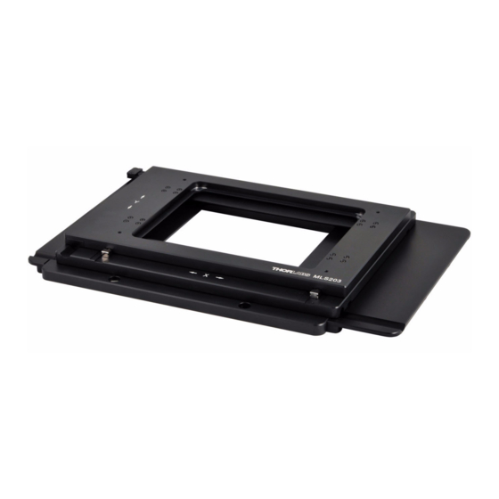
- Page 1 MLS203-1 Fast XY Scanning Stage User Guide Original Instructions HA0264T...
-
Page 2: Table Of Contents
Chaper 7 Regulatory ....................18 7.1 Declarations Of Conformity ............18 7.1.1 For Customers in Europe ..............18 7.1.2 For Customers In The USA ..............18 7.2 CE Certificates ................. 19 Chaper 8 Thorlabs Worldwide Contacts ..............20 Page 0 22115-D02... -
Page 3: Introduction
The MLS203 stages should be driven by the BBD series of brushless DC motor controllers. These controllers include the Thorlabs apt software suite, which provides an easy-to-use graphical interface for stand-alone operation as well as programming support for integrated applications. -
Page 4: Safety Information
MLS203 Series XY Scanning Stage Chapter 2 Safety 2.1 Safety Information For the continuing safety of the operators of this equipment, and the protection of the equipment itself, the operator should take note of the Warnings, Cautions and Notes throughout this handbook and, where visible, on the product itself. The following safety symbols may be used throughout the handbook and on the equipment itself. -
Page 5: Unpacking
Chapter 3 Installation Chapter 3 Installation 3.1 Unpacking Caution Once removed from its packaging, the stage can be easily damaged by mishandling. The unit should only be handled by its base, not by any attachments to the moving platform.‘ Note Retain the packing in which the unit was shipped, for use in future transportation. -
Page 6: Fitting The Finger Guards
MLS203 Series XY Scanning Stage 3.2.2 Fitting the Finger Guards The stages are supplied with finger guards to avoid trapping of body parts or cables in the mechanism. These should be fitted before the stage is mounted on the microscope as follows: 1) Offer up the finger guards to the stage as shown below, and secure using the M3 x 16 bolts supplied. - Page 7 Chapter 3 Installation 3.2.3 Mounting To A Zeiss Axio Observer/ Axiovert 40 Series Microscope The stages are mounted to the working surface by M4 screws through the base plate. 1) Remove the bolts securing the manual XY specimen stage, fitted as standard to the microscope.
-
Page 8: Electrical Connections
MLS203 Series XY Scanning Stage 3.3 Electrical Connections The stage must be driven by a Thorlabs BBD series controller. Connect the motor leads to the MOTOR DRIVE connectors, and the encoder feedback leads to the FEEDBACK connectors. Ensure that the motor drive and feedback leads for each motor are connected to the correct channel. -
Page 9: Dimensions
ACCESSORY PLATE MOUNTING SURFACE CENTRE OF STAGE TRAVEL 25.0mm 0.98in MOUNTING HOLE FOR M5 CAP SCREW 4 PLACES M3 x 0.5 TAPPED HOLE 6 PLACES 79.0mm 3.11in 72.0mm 2.83in 54.0mm 172.0mm 2.13in 6.77in Fig. 3.5 MLS203-1 Dimensions Page 7 Rev F Apr 2019... -
Page 10: General
Chapter 4 Operation 4.1 General Caution The MLS203 stages is designed to be driven by the Thorlabs BBD20x or RBD201 Brushless DC Motor Controllers. The stages are connected to the controller via 2 flying leads terminated in D-type connectors (FEEDBACK) and 2 leads terminated in round 8-Pin DIN Connectors (MOTOR DRIVE). -
Page 11: Using The Kinesis Software
PID loop parameter settings to fine tune the response - see the following section for more information. 1) If it is not already running, start the Kinesis software - Start/Programs/Thorlabs/ Kinesis/Kinesis The software reads in the stage and controller information on boot up and the GUI panel shown below is displayed.. - Page 12 MLS203 Series XY Scanning Stage 2) Click the Settings button on the GUI to display the Settings panel, then select the ‘Advanced’ tab. Fig. 4.2 Advanced Control Loop Settings 3) Create a Custom Settings Group (see the Kinesis helpfile for more information) and then adjust the acceleration and PID settings to fine tune the control loop for your application - see Table 4.1 and Table 4.2 for more information.
- Page 13 Chapter 4 Operation Depending on the shape of the mass and the accelerations and velocities used the values quoted above may require adjustment to provide optimum performance. Table 4.2 Load vs Maximum acceleration recommendations Load (g) Approximate Max Acceleration (mm/s²) 5000 2400 1550...
-
Page 14: Using The Apt Software
PID loop parameter settings to fine tune the response - see the following section for more information. 1) If it is not already running, start the APTUser utility - Start/Programs/Thorlabs/APT User/APT User The APT server reads in the stage and controller information on boot up and the GUI panel shown below is displayed.. - Page 15 Chapter 4 Operation 2) Click the Settings button on the GUI to display the Settings panel, then select the ‘Advanced’ tab. Fig. 4.4 Advanced Control Loop Settings 3) Adjust the acceleration and PID settings to fine tune the control loop for your application see Table 4.1 and Table 4.2 for more information.
-
Page 16: Position Error Messages
MLS203 Series XY Scanning Stage Table 4.2 Load vs Maximum acceleration recommendations Load (g) Approximate Max Acceleration (mm/s²) 5000 2400 1550 The values quoted above are the maximum values recommended to avoid over current errors. These values are a guideline only, and depending on the shape of the mass and the velocities used, these values may require further adjustment, particularly if the stages are mounted in an XY configuration. -
Page 17: Transportation
4.6 Maintenance The product is maintenance free. If any problems occur, the user should contact the local Thorlabs tech support for more information. 4.7 Transportation Caution When packing the unit for shipping, use the original packing. If this is not available, use a strong box and surround the unit with at least 100 mm of shock absorbent material. - Page 18 MLS203 Series XY Scanning Stage Chapter 5 Specification Parameter Value Travel 110 mm x 75 mm (4.3" x 2.95") Max Speed 250 mm/s* Acceleration 2000 mm/s* Bidirectional Repeatability 0.25 µm Unidirectional Repeatability 0.25 µm Backlash N/A (No Leadscrew) Min Incremental Movement 0.1 µm Home Location Accuracy 0.25 µm...
-
Page 19: Parts List
A range of attachment brackets is also available, which allow the stage to be fitted to specific microscopes from Nikon and Olympus - see www.thorlabs.com for more details. Rev F Apr 2019... -
Page 20: Declarations Of Conformity
MLS203 Series XY Scanning Stage Chapter 7 Regulatory 7.1 Declarations Of Conformity 7.1.1 For Customers in Europe See Section 7.2. 7.1.2 For Customers In The USA This equipment has been tested and found to comply with the limits for a Class A digital device, persuant to part 15 of the FCC rules. -
Page 21: Ce Certificates
Chapter 7 Regulatory 7.2 CE Certificates Rev F Apr 2019 Page 19... - Page 22 Waste treatment is your own responsibility. "End of life" units must be returned to Thorlabs or handed to a company specializing in waste recovery. Do not dispose of the unit in a litter bin or at a public waste disposal site.
- Page 23 www.thorlabs.com...