Table of Contents
Advertisement
Quick Links
®
Installation, Operation and Maintenance Manual
Please read and save these instructions for future reference. Read carefully before attempting to assemble,
install, operate or maintain the product described. Protect yourself and others by observing all safety
information. Failure to comply with instructions could result in personal injury and/or property damage!
General Information
This instruction manual provides installation, operating,
maintenance, and parts information for Sure-Aire™
Series Differential Pressure Controllers.
WARNING
Improper installation, adjustment, alterations, service
or maintenance can cause injury and property
damage, as well as possible voiding of factory
warranty. No person may install, operate, or maintain
the Sure-Aire Differential Pressure Controller(s)
and transmitters without first being fully trained
and qualified in the installation, operation and
maintenance, and carefully reading and understanding
the contents of this manual. If you have any
questions about these instructions, contact your local
representative.
CAUTION
Risk of electrical shock! More than one disconnect
switch may be required to de-energize the equipment
before servicing.
®
Sure-Aire™ Flow Monitoring System
User and Service Manual
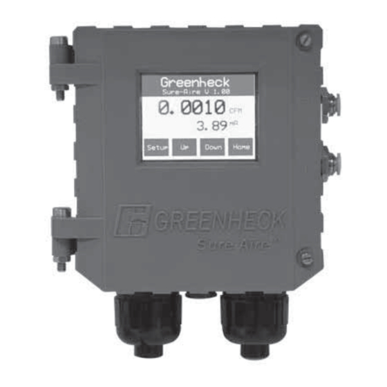
Differential Pressure Controller Features:
• NEMA-4 and IP56 enclosure rating
• Factory calibrated
• 24 Vdc or 24 Vac input voltage
• Pressure ranges:
0-8.30 inches W.C.
0-22.14 inches W.C.
0-41.52 inches W.C.
0-83.04 inches W.C.
0-138.40 inches W.C.
• Selectable isolated output transmitter linear to
differential pressure
4-20 mA
2-10 Vdc
• LCD display with user-friendly touch panel interface
• Temperature compensation
• Remote duct temperature sensor
• Programmable elevation
• English or metric readings
• Simple installation
Table of Contents
General Information . . . . . . . . . . . . . . . . . . 1
Differential Pressure Controller Features. . . . . . . . 1
Installation . . . . . . . . . . . . . . . . . . . . . . . 2
Dimensions and Hole Mounting Patterns . . . . . . 2
Wiring and System Components . . . . . . . . . . 2
Label and Order Information . . . . . . . . . . . . 2
Sure-Aire Controller Part Number . . . . . . . . . . 2
Display Setting Options and Setup . . . . . . . . . 3-4
4-20 mA Transmitter Calibration Procedure . . . . . . 5
2-10 Vdc Transmitter Calibration Procedure . . . . . . 6
Temperature Sensor . . . . . . . . . . . . . . . . . . 7
Maintenance Log. . . . . . . . . . . . . . . Backcover
Our Commitment. . . . . . . . . . . . . . . Backcover
Sure-Aire™ Flow Monitoring System
Document 476092
1
Advertisement
Table of Contents

Related Manuals for Greenheck Sure-Aire 384986

Summary of Contents for Greenheck Sure-Aire 384986
-
Page 1: Table Of Contents
Document 476092 Sure-Aire™ Flow Monitoring System User and Service Manual ® Installation, Operation and Maintenance Manual Please read and save these instructions for future reference. Read carefully before attempting to assemble, install, operate or maintain the product described. Protect yourself and others by observing all safety information. -
Page 2: Installation
Installation Dimensions and Hole Mounting Pattern 4-5/32 in. WARNING (105.6 mm) When wiring the instrument, you must follow industry standard practices for control and protection against electrostatic discharge (ESD). Failure to exercise good ESD practices may cause damage to the controller. 3-9/32 in. -
Page 3: Display Setting Options And Setup
Display Setting Options and Setup Pressure Units: Press Greenheck Edit to change pressure Menu Options: Current units. Press Prev or Next Sure-Aire V 1.00 settings are displayed Greenheck to adjust, then press in the main display area Sure-Aire V 1.00 Enter to store the value. - Page 4 Display Brightness: Transmitter Min Value: Greenheck Greenheck Press Edit to change Press Edit to change brightness. Press Inc or Transmitter Min Value. Sure-Aire V 1.00 Sure-Aire V 1.00 Dec to adjust, then press Press Inc or Dec to Enter to store the value.
-
Page 5: Ma Transmitter Calibration Procedure
2.13 Transmitter Max Value. 4-20 mA Transmitter Calibration Procedure Greenheck WARNING Sure-Aire V 1.00 Due to load resistance change from product to product, it may be necessary to recalibrate the Transmitter Max Value: 4-20 mA transmitter. 1.0 Test Equipment Exit Enter 1.1 Digital Multimeter. -
Page 6: Vdc Transmitter Calibration Procedure
Apply a vacuum to the High Port and the 2-10 Vdc transmitter will track the span of the pressure range. 24 Volts i.e. The Sure-Aire controller with a pressure sensor Greenheck ~24 V AC or DC ~24 V of 0 - 41.51 in. W.C. installed, 2.00 Vdc = 0 in. W.C.,... -
Page 7: Temperature Sensor
Temperature Sensor Specifications Interconnect the remote temperature sensor by Service: Air and non-combustible, connecting the temperature sensor to pins 4 and 5 of compatible gases TB2. The Remote Temperature Sensor will adjust the Enclosure Rating: NEMA-4 and IP56 air density value in the controller based on the sensor Dimensions: 5 x 5-3/8 x 2-1/2 inches measurement when Temperature Compensation is set (127 x 136.5 x 63.5 mm) -
Page 8: Maintenance Log
_________________________________________________ _________________________________________________ Our Commitment As a result of our commitment to continuous improvement, Greenheck reserves the right to change specifications without notice. Specific Greenheck product warranties are located on greenheck.com within the product area tabs and in the Library under Warranties.