Table of Contents
Advertisement
Advertisement
Table of Contents
Troubleshooting

Summary of Contents for Wahl ST2200
-
Page 1: Schematic
ST2200 Soldering Iron Tester User Manual W-2176 Rev E Revised 05/29/20 Palmer Wahl • 234 Old Weaverville Road • Asheville, North Carolina • 28804-1260 Phone (800) 421-2853 • (828) 658-3131 • Fax (828) 658-0728 • Email: info@palmerwahl.com www.palmerwahl.com... -
Page 2: Table Of Contents
ST2200 Soldering Iron Tester User Manual PARAGRAPH TABLE OF CONTENTS PAGE INTRODUCTION MODELS and CONTENTS SPECIFICATIONS CONTROLS AND ITEM DESCRIPTIONS OPERATION Connecting to AC Power System Connections Temperature Measurements Tip Voltage Potential Measurements REPLACEMENT SENSORS AND ACCESSORIES Sensors Probes Carrying Case... -
Page 3: Introduction
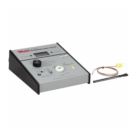
Or email: register@palmerwahl.com INTRODUCTION The Wahl Instruments Model ST2200 Soldering Iron Tester (see Fig. 1) is designed for the testing of hand-held soldering irons used in the assembly of electronic circuits and components. It is intended to be used as a quality tool to assist manufacturers in complying with Soldering Standard IPC/EIA J-STD-001C or other applicable standards. -
Page 4: Specifications
ST2200 Soldering Iron Tester User Manual The following Kits include 2 WST-02B sensors, TC800K type K Wire Probe, TC801P solder pot probe, sensor cleaning brush, 12423-01 soft carrying case and operation/calibration manual. NIST Traceable Certificate of Conformance is optional. °C display, 110 volt input voltage KST2200C-110 °F display, 110 volt input voltage... - Page 5 ST2200 Soldering Iron Tester User Manual Test Current: 10 mA DC LED Warning Indicator: Factory set at 5.00 Ohms. Switchable to 2.00 Ohms via internal jumper (see section 6.1 for details). Millivolt Specifications: Voltage Range: 0 - 30mV true RMS AC or AC+DC range.
- Page 6 ST2200 Soldering Iron Tester User Manual Spike Detect Threshold: >100mV amplitude, > 1 uS pulse width. Ambient Environment: Operational: 45°F to 105°F (7.2°C to 40.5°C) Storage: -4°F to 122°F (-20°C to 50°C) Dimensions: 8.5"W x 10.5"D x 3.5"H (21.59cm x 26.67cm x 8.89cm) Weight: 3 lbs.
-
Page 7: Control Identification
ST2200 Soldering Iron Tester User Manual Figure 1. ST2200 Soldering Iron Mil Spec Page 7 of 34... -
Page 8: Controls And Item Descriptions
This input connector is provided to interface optional Type K thermocouple probes to the ST2200 unit. With the input selector switch set to AUX T/C-K the unit will use the signal input to this connector as the source for measurements. -
Page 9: Operation
ST2200 Soldering Iron Tester User Manual The internal circuitry of the ST2200 is protected against static discharge that may be applied to the sensor during test of soldering irons or when the auxiliary thermocouple connector is used. (8) Sensor ST2200 Soldering Iron Testers are shipped with Model WST-02B heavy duty bead sensor. -
Page 10: Connecting To Ac Power
AC Convenience Outlet (4) located on the right side of the ST2200. Note that for testing soldering irons that will not be plugged into the ST2200's AC Convenience Outlet, the ST2200 should be plugged into an AC receptacle with the identical ground wire as the irons to be tested. -
Page 11: Tip Voltage Potential Measurements
Temperature recording can be made using the Recorder Output Jack. The ST2200 displays the temperature of the working surface of the tip. It may not agree with the indicated temperature of the soldering station or the setting of the soldering iron control. -
Page 12: Replacement Sensors And Accessories
Function Selector Switch to the RESISTANCE setting and touch the tip of the iron to the ST2200 sensor. If the resistance is less than 5.00 ohms the FAIL MV/OHM indicator (3) will be green. When the resistance is equal to or greater than 5.00 ohms the FAIL MV/OHM indicator (3) will flash red. -
Page 13: Sensors
ST2200 Soldering Iron Tester User Manual Sensors The ST2200 Soldering Iron Tester has several optional sensors available. The unit comes standard with the WST-02B sensor. Following is a list of model numbers and descriptions of the available sensors. WST-02B, 0.2 gram thermal mass heavy duty sensor with bonnet. -
Page 14: Probes
Please contact Wahl or visit our website for other available probes. Carrying Case 12423-01 is a soft carrying case which will hold the ST2200, spare sensors, spare probes and adapters. Provides excellent dust protection for your unit when not in use. -
Page 15: Display Resolution Setting
Resistance display resolutions. These are not independently changeable. 6.1.2 Resistance Threshold The ST2200 is factory set at 5.00 ohms but is user selectable, via jumpers, to change the FAIL MV/OHM Indicator threshold resistance between 2.00 ohms and 5.00 ohms. -
Page 16: Display Resolution Jumper Locations
ST2200 Soldering Iron Tester User Manual Figure 3 Display Resolution Jumper Locations Page 16 of 34... -
Page 17: Sensor Repair
ST2200 Soldering Iron Tester User Manual Sensor Repair Sensors for the ST2200 are very sturdy and will give long life if not subjected to excessive force during use. All sensors are repairable in the field. (with the exception of model WST-01 (Discontinued.) See section 5.2 for repair and tooling kits. -
Page 18: Sensor Repair - Band Replacement
ST2200 Soldering Iron Tester User Manual Page 18 of 34... -
Page 19: Calibration Procedure
ST2200 Soldering Iron Tester User Manual CALIBRATION PROCEDURE Purpose To describe instructions to calibrate Soldering Iron Tester Model ST2200 with suffixes F or C and -110 or -220. Scope This instruction applies to the above noted models and is to be used by qualified electronic technicians. -
Page 20: A/D And Temperature Calibration Setup
ST2200 Soldering Iron Tester User Manual Figure 5. Temperature Calibration Figure 6. Ohms Calibration Page 20 of 34... - Page 21 7.8.1 Remove bottom cover and place UUT on its side. 7.8.2 Connect DVM (-) to TP3, (+) to TP6. 7.8.3 Remove ST2200 sensor and connect T/C Simulator, via T/C wire set to banana plugs on front panel. Red wire is negative (-). ST2200 banana plug furthest from the LCD is negative input.
- Page 22 7.12.7 Set Decade Box to 50.00 ohms and adjust R50 for a reading equal to the value of lead resistance found in step 7.12.3 plus 50.00 ohms. For example, the ST2200 display should display 50.20 ohms, for a measured lead resistance of 0.20 ohms.
- Page 23 7.13.1 Connect the Millivolt source, True RMS Millivolt meter (AC reference voltmeter) to ST2200 as shown in Figure 7. For best results, solder a small piece of wire to the solder bead of the tip sensor and attach the alligator clip from the AC Millivolt source to it.
-
Page 24: Millivolt Calibration Setup
ST2200 Soldering Iron Tester User Manual Figure 7. Millivolts Calibration Figure 8. Spike Test Page 24 of 34... - Page 25 7.14 Millivolt Calibration AC + DC NOTE: The ST2200 measures the True RMS of the sum total of AC + DC voltages presented to the sensor with respect to power ground. There is no separate adjustment for the AC + DC function. It is calibrated when the calibration is performed on the AC ONLY function.
-
Page 26: Applications, Technical Information And Troubleshooting
APPLICATIONS, TECHNICAL INFORMATION AND TROUBLESHOOTING Solder Pot and Wave Solder Machines The ST2200 may also be used to measure solder pot and solder machine temperature, voltage potential and ground resistance. Use the supplied wire probe or the Optional Pot Solder Probe model TC801P. - Page 27 AC power cord connections is reversed. Therefore, as little as 10 millivolts of either polarity will cause a variance of the ST2200 digital display of ±1.0 ohms as the scale factor is 1.0 ohms per 10 millivolts of the voltage measured.
-
Page 28: Circuit Description
ST2200 Soldering Iron Tester User Manual Circuit Description Figure 9 is a simplified block diagram of the ST2200. There are six distinct measuring capabilities shown. During temperature measurement, the thermocouple characteristics of the type K sensor are used and the microvolt... - Page 29 AC line. The display should indicate 0.00 to 0.10mV for a "zero" input. If it is out of this range, the ST2200 may need calibration or repair. Try reconnecting the ST2200 AC cord at the AC line and try again. The contact resistance of the ground connection at the AC line is not a major factor, but if it is over 100 ohms, erratic readings may appear.
- Page 30 If a wrist strap under test indicates a failure, following are possible causes. 1. Check that the wrist strap cable connector is connected properly to the ST2200. See Figure 1, Item 9 for wrist strap connector location. Do not rely on common ground of AC line for wrist strap testing.
-
Page 31: Simplified System Block Diagram
ST2200 Soldering Iron Tester User Manual Figure 9. ST2200 Simplified System Block Diagram Page 31 of 34... -
Page 32: Component Layout Diagram
ST2200 Soldering Iron Tester User Manual Figure 10. Component Layout Diagram Page 32 of 34... - Page 33 ST2200 Soldering Iron Tester User Manual Figure 11. Schematic Diagram Page 33 of 34...
- Page 34 ST2200 Soldering Iron Tester User Manual Figure 11. Schematic Diagram - page 2 Page 34 of 34...