Table of Contents
Advertisement
WONDERFIRE ELECTRONIC V LVE
INST LL TION & OPER TING M NU L
Nectre Wonderfire fire boxes are approved to be installed as a zero
clearance firebox and are designed to operate on Natural Gas.
Approval Number: AGA 4464 G
Installed primarily as a decorative appliance. Not certified as a Space Heater.
VERSION 1
Advertisement
Table of Contents

Summary of Contents for Nectre Fireplaces WONDERFIRE
- Page 1 WONDERFIRE ELECTRONIC V LVE INST LL TION & OPER TING M NU L Nectre Wonderfire fire boxes are approved to be installed as a zero clearance firebox and are designed to operate on Natural Gas. Approval Number: AGA 4464 G Installed primarily as a decorative appliance.
- Page 2 W RR NTY INFORM TION The benefits provided to you under the following warranty are in addition to any other rights and remedies available to you under the law. 1. Warranty during the first 10 years from the date of purchase (Firebox Warranty Period), there is a defect in the firebox of the Gas Burner;...
- Page 3 INST LL TION NOTICE The installation of this appliance is only to be carried out by an authorised person in accordance with the Manufacturer’s Instructions, local gas fitting regulations, AS/NZS5601.1-2013 installation code for gas burning appliances and any other relevant statutory regulations. In all cases the installation of this appliance shall meet the requirements as set out in AS/NZS5601.1-2013 NOTE: A slight smell may be apparent for the first few hours of use.
-
Page 4: Table Of Contents
CONTENTS Contents .........................4 Data Plate .......................5 Dimensions ......................5 Operating Instructions - Customer................6 Technical Data ......................8 System Description....................9 Installation......................10 Operating Procedure ....................12 Installation Instructions - Installer .................17 Commissioning .....................19 Maintenance/Fault Finding ...................19 Servicing Details ....................19 Fault Finding Chart ....................22 Sequence of Operation..................23 Regulator Adjustment &... -
Page 5: Data Plate
(Affixed to the base of the unit for reference to gas pressure & consumption) D T PL TE AF18 OF Automatic valve (Sit Proflame) Injector Size (mm) N.G.C. (Mj/Hr) Natural Gas 1 x injector multiport 7 ports x 1.25 0.88 kPa high 35 high DIMENSIONS 320mm... -
Page 6: Operating Instructions - Customer
Caring for your Nectre Wonderfire Your Nectre Wonderfire has been designed for ease of use and is very easy to maintain. The fire is a sealed unit and there are no user serviceable components inside, other than the batteries. - Page 7 OPER TING INSTRUCTIONS - Customer The Nectre Wonderfire has fully automatic controls and must be connected to gas and have good batteries to operate. Before trying to turn on your fire for the first time check that it has been properly installed and tested by a qualified installer.
-
Page 8: Technical Data
TECHNIC L D T Remote Control Supply voltage 4.5 V (three 1.5 V AAA batteries) Ambient temperature ratings 0-50 DEG C (32-122 DEG F) Radio frequency 315 MHz Receiver Supply voltage 6.0 V (four 1.5 V AA batteries) Ambient temperature ratings 0-60 DEG C (32-140 DEG F) Radio frequency 315 MHz... -
Page 9: System Description
SYSTEM DESCRIPTION The Proflame Remote Control System consists of two elements. 1. Proflame transmitter. 2. Proflame receiver and wiring harness to connect the receiver to the gas valve stepper motor. TRANSMITTER (REMOTE CONTROL WITH LCD DISPLAY) The Proflame Transmitter uses a streamline design with a simple button layout and informative LCD display (Fig.1) The Transmitter is powered by 3 AAA type batteries. -
Page 10: Installation
6. Using the two screws provided, secure the cover plate to the receiver. AC/DC Power Pack Your Nectre Wonderfire comes with a AC switch mode power pack which is required to be plugged into a separate 10amp 240VAC outlet. Output = 7.5V DC 600Ma... - Page 11 (continued) INST LL TION Connecting to the Gas Valve The wiring harness for the Proflame GTM system has two wires labeled “TH” & “TPTH”. Connect the wires to the gas valve as labeled. (TH to TH and TPTH to TPTH). Additionally there is a connector labeled “Motor”.
-
Page 12: Operating Procedure
OPER TING PROCEDURE Initialising the system for the first time Temperature Indication Display Fig. 6: Remote Control display in Faranheit and Celcius Fig. 7: Remote Control display... - Page 13 (continued) OPER TING PROCEDURE Turn on the appliance Turn off the appliance Remote Flame Control Fig. 8 Fig. 9...
- Page 14 (continued) OPER TING PROCEDURE Room Thermostat (Transmitter Operation) Fig. 10 Fig. 11 Smart Thermostat (Transmitter Operation) Fig. 12: Smart flame function Fig. 13...
- Page 15 (continued) OPER TING PROCEDURE Key Lock Fig. 18 Low Battery Power Detection Fig. 19 Manual bypass of the remote system...
- Page 16 (continued) OPER TING PROCEDURE W RNING C UTION...
-
Page 17: Installation Instructions - Installer
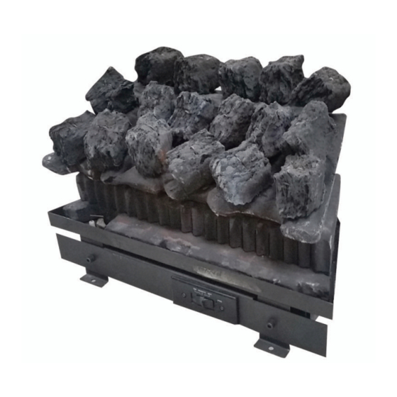
This appliance must be installed in accordance with; the manufactures installation instructions, Municipal building codes, and any other relevant statutory regulations • The Nectre Wonderfire Gas Fire is only to be used with natural gas. Please refer to the “Servicing Details” section of these instructions. •... - Page 18 Note: Do not bring the gas supply down the active chimney. Coals The Nectre Wonderfire has ceramic coals and a burner designed to appear like a wood/ coal fire. The unit is supplied with the ceramics assembled ready for operation.
-
Page 19: Commissioning
Please refer to the fault finding table as a trouble shooting guide. Please refer to the section “Caring for Your Nectre Wonderfire” for user maintenance. SERVICING DET ILS The following notes are to assist a serviceman in the event of a malfunction. - Page 20 (continued) SERVICING DET ILS G S CONTROL – Proflame 885 The SIT electronic gas control and valve is situated under the burner tray. To access; remove the coals and disconnect the gas supply. Remove the burner and place upside down on a flat surface covered with old newspaper.
- Page 21 (continued) SERVICING DET ILS BURNER To access the burner remove the coals. The burner is glued in to the burner tray. Examine it for any damage and check the venturi at the rear for lint and dust. Carefully clean as required. Ensure that the main injector is located centrally with respect to the venturi.
-
Page 22: Fault Finding Chart
F ULT FINDING CH RT Fault Possible Cause Corrective Action Igniter does not Spark rod at pilot light shorting. Clean Insulator or replace If damaged. spark. Faulty spark cable. Replace (with genuine part only). Reconnect. Spark cable disconnected. Igniter sparks but Low batteries. -
Page 23: Sequence Of Operation
SEQUENCE OF OPER TION Remote control calls for heat and sends signal. Signal received by receiver. Beep sound should be audible from appliance. Receiver performs internal safety check. Gas control actuates pilot gas and starts ignition of pilot. Ignition sparks for pilot. Upon pilot lighting flame sensing occurs and sparking stops. -
Page 24: Wiring Diagram
WIRING DI GR M... -
Page 28: Glen Dimplex Contact Information
GLEN DIMPLEX AUSTRALIA PTY LTD ABN 69 118 275 460 Head Office/Factory/Showroom 1340 Ferntree Gully Rd. Scoresby Vic 3179 Ph: 1300 554 155 Fax: (03) 8706 2001...