H3C WX1800H Series Installation Manual
Hide thumbs
Also See for WX1800H Series:
- User configuration manual (57 pages) ,
- Installation manual (51 pages) ,
- Command reference manual (27 pages)

Related Manuals for H3C WX1800H Series


Summary of Contents for H3C WX1800H Series
- Page 1 H3C WX1800H Series Access Controllers Installation Guide New H3C Technologies Co., Ltd. http://www.h3c.com.hk Document version: 5W101-20170906...
- Page 2 , H3CS, H3CIE, H3CNE, Aolynk, Care, , IRF, NetPilot, Netflow, SecEngine, SecPath, SecCenter, SecBlade, Comware, ITCMM and HUASAN are trademarks of New H3C Technologies Co., Ltd. All other trademarks that may be mentioned in this manual are the property of their respective owners Notice The information in this document is subject to change without notice.
- Page 3 Preface This installation guide describes the installation procedure for the H3C WX1800H series access controllers. This preface includes the following topics about the documentation: • Audience. • Conventions • Obtaining documentation • Technical support • Documentation feedback Audience This documentation is intended for: •...
- Page 4 Convention Description Multi-level menus are separated by angle brackets. For example, File > Create > > Folder. Symbols Convention Description An alert that calls attention to important information that if not understood or followed WARNING! can result in personal injury. An alert that calls attention to important information that if not understood or followed CAUTION: can result in data loss, data corruption, or damage to hardware or software.
- Page 5 Obtaining documentation To access the most up-to-date H3C product documentation, go to the H3C website at http://www.h3c.com.hk To obtain information about installation, configuration, and maintenance, click http://www.h3c.com.hk/Technical_Documents...
-
Page 6: Table Of Contents
Contents Preparing for installation ···································································· 1 Safety recommendations ············································································································· 1 General safety recommendations ··························································································· 1 Electricity safety ·················································································································· 1 Examining the installation site ······································································································· 1 Temperature and humidity ····································································································· 1 Cleanliness ························································································································ 2 Cooling ·····························································································································... - Page 7 WX1810H-PWR ················································································································ 23 WX1820H ························································································································ 24 Technical specifications ············································································································· 24 Interface arrangement ··············································································································· 25 WX1804H-PWR ················································································································ 25 WX1810H-PWR ················································································································ 25 WX1820H ························································································································ 25 Appendix B LEDs ··········································································· 26 WX1804H-PWR ······················································································································ 26 WX1810H-PWR ······················································································································...
-
Page 8: Preparing For Installation
Preparing for installation Safety recommendations General safety recommendations To avoid any equipment damage or bodily injury, read the following safety recommendations before installation. Note that the recommendations do not cover every possible hazardous condition. • Make sure the installation site is flat, vibration-free, and away from electromagnetic interferences. -
Page 9: Cleanliness
• Lasting low relative humidity can cause washer contraction and ESD and cause problems including loose mounting screws and circuit failure. • High temperature can accelerate the aging of insulation materials and significantly lower the reliability and lifespan of the device. Table 1 Temperature and humidity requirements for the equipment room Temperature Relative humidity... -
Page 10: Emi
• Always wear ESD gloves and ESD garment and remove conductive objects such as jewelry or watch before working with the device. All electromagnetic interference (EMI) sources, from outside or inside of the device and application system, adversely affect the device in the following ways: •... -
Page 11: Pre-Installation Checklist
Figure 3 Installation accessories for the WX1820H access controller Pre-installation checklist Table 4 Pre-installation checklist Item Requirements Result • A minimum clearance of 10 cm (3.9 in) is reserved around the chassis. Ventilation • The installation site has a good ventilation system. •... -
Page 12: Installing The Device
Installing the device IMPORTANT: Keep the tamper-proof seal on a mounting screw on the chassis cover intact, and if you want to open the chassis, contact H3C for permission. Otherwise, H3C shall not be liable for any consequence. Installation prerequisites •... -
Page 13: Mounting The Device On A Workbench
Figure 5 Installation flowchart for the WX1810H-PWR access controller Mounting the device on a workbench CAUTION: • To avoid damaging the device and affecting heat dissipation, do not place heavy objects on the device. • Make sure the workbench is anti-static. -
Page 14: Mounting The Device In A 19-Inch Rack
The installation procedure is similar for WX1800H series access controllers. This guide uses the WX1804H-PWR access controller as an example. To mount the device on an anti-static workbench: Place the device upside down on the workbench. Use a cloth to clean the recessed areas on the bottom. - Page 15 Figure 8 Attaching the mounting brackets to the device Supporting the bottom of the device with one hand and holding the front of the device with the other, put the device in the rack. Use M6 screws and cage nuts to attach the mounting brackets to the front rack posts, as shown in Figure 9.
-
Page 16: Connecting The Grounding Cable
Connecting the grounding cable CAUTION: • Correctly connecting the grounding cable is crucial to lightning protection and EMI protection. To install and use the device, first connect the grounding cable reliably for the device. • Connect the grounding cable to the grounding system in the equipment room. Do not connect it to a fire main or lightning rod. - Page 17 Figure 11 Grounding the device with a grounding strip Grounding the device through the rack—Connect the other end of the grounding cable to the grounding terminal on the rack and make sure the rack has been reliably grounded. Only the WX1810H-PWR access controller supports this grounding method. Figure 12 Grounding the device through the rack...
-
Page 18: (Optional) Installing Network Port Lightning Protectors
(Optional) Installing network port lightning protectors IMPORTANT: • Before installing a network port lightning protector, read the instructions in the document that comes with the protector. • Network port lightning protectors are available only for 10M/100M/1000M RJ-45 Ethernet copper ports. •... -
Page 19: (Optional) Installing A Surge Protected Power Strip
Figure 13 Installing a lightning protector for a network port (Optional) Installing a surge protected power strip IMPORTANT: Before installing a surge protected power strip, read the instructions in the document that comes with the strip. If you use an AC power line routed from outdoors for the device, use a surge protected power strip for the device to protect against damages caused by lightning strikes. -
Page 20: Connecting The Power Cord
Figure 14 Connecting the device to the network Connecting the power cord CAUTION: Before connecting the power cord, make sure the local AC power source is reliably grounded. Connecting the power adapter for the WX1804H-PWR/WX1820H access controller If you use the local power source for the WX1804H-PWR/WX1820H access controller, use a power adapter to connect the device to the power source. -
Page 21: Connecting The Power Cord For The Wx1810H-Pwr Access Controller
Connecting the power cord for the WX1810H-PWR access controller Make sure the device is reliably grounded. Connect one end of the AC power cord to the AC power receptacle on the device. Connect the other end of the AC power cord to the AC power source. Observe the LEDs on the device to verify that the power cord is connected correctly. - Page 22 It will take a long time to get configuration file, please wait... Retrieving configuration file failed! User interface con0 is available. Press ENTER to get started. Press Enter at the prompt, and you can configure the device when the prompt <H3C> appears.
-
Page 23: Troubleshooting
Verify that the power source is as required by the device. Verify that the power cord is connected securely. Verify that the power cord is in good condition. If the problem persists, contact H3C Support. No display or garbled display on the configuration terminal... -
Page 24: Software Loading Failure
You used TFTP to load software and entered an incorrect IP address, software name, or TFTP serve path. You used FTP to load software and entered an incorrect IP address, software name, username, or password. If the problem persists, contact H3C Support. -
Page 25: Hardware Management And Maintenance
=============================================== ===============display clock=============== 00:04:29 UTC Fri 01/01/2017 ================================================= ===============display version=============== H3C Comware Software, Version 7.1.064, Release 5204P01 Copyright (c) 2004-2017 New H3C Tech. Co., Ltd. All rights reserved. H3C WX1804H-PWR uptime is 0 weeks, 0 days, 0 hours, 4 minutes... -
Page 26: Displaying Information About The Device
Status: Normal Type: WX1804H-PWR Hardware: A Driver: 0.22 … Displaying information about the device Use the display device command to display information about the device. <H3C> display device Slot No. Subslot No. Board Type Status Max Ports WX1804H-PWR Normal Table 5 Command output... -
Page 27: Displaying The Electronic Label Data For The Device
An electronic label is a profile of a device. It contains the permanent configuration, including the serial number, manufacturing date, MAC address, and vendor name. Use the display device manuinfo command to display the electronic label data for the device. <H3C> display device manuinfo DEVICE_NAME:UNKNOWN DEVICE_SERIAL_NUMBER:219801A17YH133000015... -
Page 28: Configuring The Exception Handling Method
-/+ Buffers/Cache: 228436 788112 Swap: Table 8 Command output Field Description Slot x Slot number of the device. Memory usage information. Total Total size of the physical memory space that can be allocated. Used Used physical memory. Free Free physical memory. Shared Physical memory shared by processes. -
Page 29: Rebooting The Device Immediately At The Cli
You can reboot the device in one of the following ways: • Reboot the device immediately at the CLI. • At the CLI, schedule a reboot to occur at a specific time and date or after a delay. • Power cycle the device. This method might cause data loss or hardware damage, and is the least preferred method. -
Page 30: Appendix A Chassis Views And Technical Specifications
Appendix A Chassis views and technical specifications WX1804H-PWR Figure 17 Front panel (1) Grounding screw (2) Power receptacle (3) 100/1000BASE-T autosensing Ethernet copper port (WAN) (4) 100/1000BASE-T PoE+ autosensing Ethernet copper ports (LAN1 to LAN4) (5) USB port (6) Console port (7) Reset button (RESET) Figure 18 Rear panel WX1810H-PWR... -
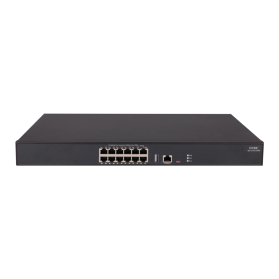
Page 31: Wx1820H
Figure 20 Rear panel (1) Grounding screw (2) Power receptacle WX1820H Figure 21 Front panel (1) Power receptacle (2) 100/1000BASE-T autosensing Ethernet copper ports (LAN1 to LAN4 and WAN) (3) Console port (4) SD card slot (5) USB port (6) Reset button (RESET) Figure 22 Rear panel (1) Kingston security slot (2) Grounding screw... -
Page 32: Interface Arrangement
Item WX1804H-PWR WX1810H-PWR WX1820H 1GB NAND flash Storage medium 1GB NAND flash memory 1GB NAND flash memory memory Dimensions (H × W × 27 × 220 × 145.5 mm 43.6 × 440 × 260 mm 28 × 220 × 146 mm (1.10 (1.06 ×... -
Page 33: Appendix B Leds
Appendix B LEDs WX1804H-PWR Figure 23 WX1804H-PWR LEDs (1) LED for the 100/1000BASE-T autosensing Ethernet copper port (2) LEDs for the 100/1000BASE-T PoE+ autosensing Ethernet copper ports (3) System status LED (SYS) (4) Bluetooth LED (BLE) (5) PoE status LED (PoE) WX1810H-PWR Figure 24 WX1810H-PWR LEDs (1) LEDs for the 100/1000BASE-T PoE+ autosensing Ethernet copper ports... -
Page 34: Led Description
LED description Status Description Steady green A 1000 Mbps link is present. 100/1000BASE-T or Flashing green Data is being received or transmitted at 1000 Mbps. 100/1000BASE-T PoE+ autosensing Steady yellow A 100 Mbps link is present. Ethernet copper port Flashing yellow Data is being received or transmitted at 100 Mbps. -
Page 35: Index
Index A C D E G I L R S T W Installation accessories,3 Attaching the ring terminal to a grounding cable,9 Lightning protection,3 Cleanliness,2 Connecting the grounding cable,9 Rebooting the device,21 Connecting the power adapter for the Rebooting the device immediately at the CLI,22 WX1804H-PWR/WX1820H access controller,13...