Table of Contents
Advertisement
Quick Links
Advertisement
Table of Contents

Related Manuals for NARDA nardalert S3


Summary of Contents for NARDA nardalert S3
- Page 1 S3 Personal Monitor Operating Manual...
- Page 2 This Monitor should only be used after you have read this manual, understood how it operates and consulted with your company’s safety officer. Narda Safety Test Solutions GmbH Sandwiesenstrasse 7 72793 Pfullingen, Germany ® Names and logo are registered...
-
Page 3: Table Of Contents
Dangers from electromagnetic fields ............. 10 Measurement errors ................... 10 Sensor is not installed or operating properly............11 Dangers from AC mains charger ..............11 Preparing the Nardalert S3 for use ..............12 Unpacking ......................12 Packaging ......................12 Items included ....................13 Transport damage .................... - Page 4 Nardalert S3 default alarm levels ..............26 Special environmental operations ..............26 Heavy rain or snow ....................26 High RF/microwave environments ..............27 Using the Nardalert S3 as an area monitor ............27 Cleaning, maintenance, repair ................28 Cleaning ......................28 Performing calibration ..................29 Repair ........................29 Verification overview ..................29...
-
Page 5: Useful Information
Useful information This chapter contains basic information about measuring electromag- netic fields, about using the Nardalert S3, and about the structure of this Operating Manual. Measuring electromagnetic fields About this monitor About this Operating Manual 1.1 Measuring electromagnetic fields In today’s world, many industries utilize equipment that generates electromagnetic fields. -
Page 6: Applications
RF heating, tempering, or drying equipment Monitoring to ensure the safety of persons using diathermy • equipment and other medical equipment that generates high frequency radiation Field strength monitoring in TEM cells, absorber chambers or test • ranges Nardalert S3... -
Page 7: About This Operating Manual
Indicates a hazardous situation which, if not avoided, will DANGER result in death or serious injury. Structure of warnings All warnings are structured as follows: ⚠ SIGNAL WORD Type and source of danger Consequences of failure to observe warning Instructions for preventing danger Nardalert S3... -
Page 8: Symbols And Marks Used In This Document
Open the MAIN menu. Cross reference (in PDF document only) Indicates a cross reference to another part of the Blue Type document. Click on the blue type in the PDF document to jump directly to the cross reference. Nardalert S3... -
Page 9: Safety Instructions
The NS3 is a warning device that gives active notice of the existence of dangerous fields by means of a visible and audible warning signal. Only use the instrument for the purpose and under the conditions for which it has been designed. Nardalert S3... -
Page 10: Dangers From Electromagnetic Fields
Affix labels of any type only to the yellow housing. Metallic labels must be affixed to the rear of the monitor. If the instrument malfunctions, take it out of service and contact your Narda Sales Partner. The addresses are listed on the Internet at www.narda-sts.com. Nardalert S3... -
Page 11: Sensor Is Not Installed Or Operating Properly
Only supply AC voltage that meets the voltage specified at the AC input on the Charger. The AC mains charger could be destroyed if the voltage specification of the charger does not match the AC line voltage. Nardalert S3... -
Page 12: Preparing The Nardalert S3 For Use
Preparing the Nardalert S3 for use This chapter describes all you need to do before starting to use the Nardalert S3. Unpacking Battery Installation Instrument overview Connecting the sensor 3.1 Unpacking Packaging The packaging is designed to be re-used as long as it has not been damaged. -
Page 13: Items Included
3 Preparing the Nardalert S3 for use Items included Check that all the following items have been delivered: Carrying Case (2270/90.02) • Nardalert S3 Mainframe (2270/01) • Silicon Sleeve (2270/90.03), attached to the mainframe • Lanyard Clip, non-conductive (2270/90.04) •... -
Page 14: Transport Damage
In the event of an incomplete delivery and damages to the device or accessories, please contact your Narda sales partner. You can find the Narda sales partner responsible for you on the Narda website at www.narda-sts.com. After transport and storage... -
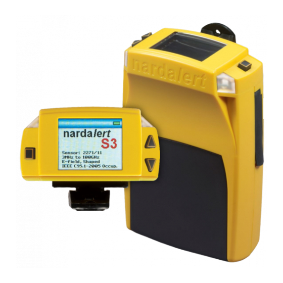
Page 15: Instrument Overview
3 Preparing the Nardalert S3 for use 3.3 Instrument overview Top Panel Alarm LEDs Up Arrow (Increase) Power On/Off and Enter Key Down Arrow (Decrease) Front Panel Rear Panel Alarm LEDs Calibration Label Interchangeable Sensor Sensor Removal Screws (2) Nardalert S3... -
Page 16: Side Panels
3 Preparing the Nardalert S3 for use Side Panels Mini-USB port for charging and data transfer. Fiber Optic port for data transfer only. Rechargeable and replaceable battery located under door. Silicon sleeve for Nardalert protection Nardalert S3... -
Page 17: Connecting The Sensor
3 Preparing the Nardalert S3 for use 3.4 Connecting the sensor ⚠ WARNING Strong electromagnetic fields If the Sensor is not operating properly, or if the proper sensor is not chosen, you could be exposed to high field levels without your knowledge. -
Page 18: Wrong Handling Of The Sensor
Ordering Information on page 38, as well as in the data sheet of the NS3. These documents can also be downloaded from the Narda website on the internet at www.narda-sts.com. Wrong handling of the sensor Damage of the sensor antennas ... -
Page 19: Getting Started
Getting started This chapter describes how to switch on the Nardalert S3 and verify it is operating properly. Initial display screens Checking monitor functions Screen navigation Additional capabilities of optioned units 4.1 Initial display screens The NS3 is switched on by depressing and holding the On/Off button on the left side of the display. -
Page 20: Normal Operation
Green to Yellow (Alarm 1) and from Yellow to Red (Alarm 2), if two alarms are used. If only one alarm is used, then the color bar will change from Green to Red (Alarm). The wearer also receives audible, vibrate and LED visual indications when alarm thresholds are exceeded (factory defaults). Nardalert S3... -
Page 21: Checking Monitor Functions
The commonly used frequency of 433 MHz will produce an upscale indication for both the low and high frequency sensors, providing a more complete verification. Nardalert S3... -
Page 22: Screen Navigation
2. If the selection process is not active, move the Screen. Scroll the previous arrow icon down to the next item. Down text if necessary. screen if unit Arrow is not in a Hold safety alarm second) state. Nardalert S3... -
Page 23: Additional Capabilities Of Optioned Units
Sets fiber optic interface for communication or remote vibrator operation. Factory default is the communication setting. History Displays maximum, minimum and average readings for the last 6 minutes. Last Calibration Displays last calibration dates for sensor and monitor. Nardalert S3... -
Page 24: Navigating Sub-Menu Screen Example
“Save and Exit” line (by tapping twice). Tap the key to return to the menu selection screen. Nardalert S3... -
Page 25: Operation Overview
Normal operation Nardalert S3 default alarm levels Special environmental operations Using the Nardalert S3 as an area monitor 5.1 Normal operation The NS3 should be fully charged and configured for your personal use. The factory provides both a lanyard attachment and a belt clip for your convenience, and a silicon skin to help provide protection for the unit against shock. -
Page 26: Nardalert S3 Default Alarm Levels
100% reading on the NS3. However, the NS3 cannot typically perform time and spatial averaging when being used as a wearable monitor. Therefore, Narda has historically recommended that a 50% alarm be used to warn the wearer of the presence of strong fields and a 200% reading to warn the wearer to leave the area. -
Page 27: High Rf/Microwave Environments
Currents flowing through the clothing could cause the monitor to false alarm. 5.4 Using the Nardalert S3 as an area monitor The NS3 functions as an effective, stand-alone area monitoring device. It may be operated continuously from the USB supply while employing the Fiber Optic interface for communicating field level information back to a computer. -
Page 28: Cleaning, Maintenance, Repair
Unsuitable cleaning methods Solvents can damage the Nardalert S3 or the charger. Water can damage the charger. Do not use solvents to clean the Nardalert S3 and charger. As cleaning fluid, we recommend the use of lukewarm water to which a drop of liquid detergent has been added. -
Page 29: Performing Calibration
For calibration, send the device to your Narda sales partner. You can find the Narda sales partner responsible for you on the Narda website at www.narda-sts.com. All NS3 mainframes need to be returned to their local calibration facility at least once every 4 years for replacement of their internal clock battery. -
Page 30: Theory Of Operation
Units should pass the “Turn-on” sequence and indicate full or nearly full battery condition. After successful completion of operational testing, units should be connected to a computer through the Fiber Optic port, to verify Nardalert S3... -
Page 31: Disposal
6.5 Disposal Disposing of Nardalert S3 The Nardalert S3 is a high-quality device that can be expected to function for a long time. Nevertheless, this device will eventually reach the end of its service live. At that time, be aware that electrical devices must be properly disposed of. -
Page 32: Specifications
Specifications Monitor specifications Sensor specifications Outline drawing Declaration of conformity Declaration of origin Nardalert S3... -
Page 33: Monitor Specifications
230 g (0.5 lb), mainframe with sensor Accessories Carrying Case, AC Charger with Plugs, Car Charger (included) Adapter, Charger/Data cable (USB 2.0), Belt Clip, Lanyard Clip, Screwdriver, Manual, NS3-TS Software, Calibration Certificate Notes: a Memory function only available to “Optioned” units. Nardalert S3... -
Page 34: Sensor Specifications
3000% of Standard or Guidance Peak Overload 32 dB above Standard or Guidance Recommended 2 Years for Sensors (P/N 2271/XX) Calibration Interval Notes: a Percentages related to the highest power density allowed by Standard or Guidance (Controlled, Occupational). 7.3 Outline drawing Nardalert S3... -
Page 35: Declaration Of Conformity
7 Specifications 7.4 Declaration of conformity Nardalert S3... -
Page 36: Declaration Of Origin
7 Specifications 7.5 Declaration of origin Country of origin Germany Nardalert S3... - Page 37 7 Specifications Nardalert S3...
-
Page 38: Ordering Information
Ordering information This chapter contains the information needed for ordering the NS3, together with its sensors and accessories. Nardalert S3 part numbers Sensor part numbers Optional accessories Nardalert S3... -
Page 39: Nardalert S3 Part Numbers
8 Ordering information 8.1 Nardalert S3 part numbers NARDALERT S3 MONITOR SET INCLUDES: Nardalert S3 Mainframe (2270/01) Carrying Case (2270/90.02) Silicon Sleeve (2270/90.03), attached to the mainframe Lanyard Clip, non-conductive (2270/90.04) Belt Clip, non-conductive (2270/90.05) Screwdriver Phillips 0 (2270/90.06) User's Guide and CD-ROM with Software NS3-TS (2270/90.07) Car Charger Adapter, USB 5V (2259/92.20) - Page 40 Narda Safety Test Solutions GmbH Sandwiesenstrasse 7 72793 Pfullingen, Germany Phone +49 7121 97 32 0 info.narda-de@L3Harris.com L3Harris Narda-STS North America Representative Office 435 Moreland Road Hauppauge, NY11788, USA Phone +1 631 231 1700 NardaSTS@L3Harris.com Narda Safety Test Solutions S.r.l.