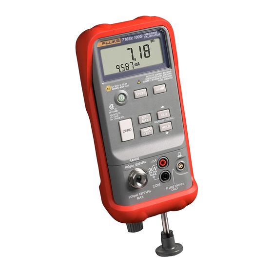
Fluke 718Ex 30G User Manual
Pressure calibrator
Hide thumbs
Also See for 718Ex 30G:
- User manual (36 pages) ,
- Calibration manual (98 pages) ,
- Specifications (2 pages)
Table of Contents
Advertisement
Quick Links
Advertisement
Table of Contents

Related Manuals for Fluke 718Ex 30G


Summary of Contents for Fluke 718Ex 30G
- Page 1 718Ex 30G/100G/300G Pressure Calibrator Users Manual May 2004 Rev. 3, 5/19 © 2004-2019 Fluke Corporation. All rights reserved. Specifications are subject to change without notice. All product names are trademarks of their respective companies.
- Page 2 Fluke warrants that software will operate substantially in accordance with its functional spec- ifications for 90 days and that it has been properly recorded on non-defective media. Fluke does not warrant that software will be error free or operate without interruption.
-
Page 3: Table Of Contents
Zeroing with Absolute Pressure Modules ............... 11 Calibrating a P/I Transmitter ................... 13 Using the Internal Pump .................... 13 Using an External Pump .................... 17 External Fluke Pressure Module Compatibility ............... 19 Switch Test ........................20 Maintenance ........................20 In Case of Difficulty ....................21 Cleaning ........................ - Page 4 718Ex 30G/100G/300G Users Manual Replacing the Battery ....................22 Approved Batteries ....................23 Parts and Accessories ....................24 Specifications ......................... 25 Specifications ......................... 25 Pressure Sensor Input ....................25 Pressure Sensor Range and Resolution ..............26 Pressure Module Input ....................26 DC mA Input ......................
-
Page 5: Introduction
Full-scale pressure sensor input is as follows: Read Safety Information before using the Calibrator. Model 718Ex 30G: 30 psi (206.85 kPa, 2.0685 bar). • OL appears at 33 psi. The Fluke Model 718Ex 30G, 718Ex 100G, and 718Ex Model 718Ex 100G: 100 psi (689.5 kPa, 6.895 bar). -
Page 6: Contact Fluke
Contacting Fluke. To order replacement parts or spares, Safety and electrical symbols used in this manual and on see Parts and Accessories. the Calibrator are displayed in Table 1. Contact Fluke To contact Fluke, call one of the following telephone numbers: • Technical Support USA: 1-800-44-FLUKE (1-800-443-5853) •... - Page 7 Pressure Calibrator Safety Information Table 1. Symbols Symbol Meaning WARNING. RISK OF DANGER. Consult user documentation. Power ON/OFF Earth ground Pressure Double insulated Battery Conforms to the European Explosive Atmospheres (ATEX) directive. Certified by CSA Group to North American safety standards.
- Page 8 Use the Calibrator only as described in • To prevent damage to the unit under test, • this User Manual and the Fluke 718Ex be sure the Calibrator is in the correct CCD (Concept Control Drawing) or the mode before connecting the test leads.
- Page 9 Remove the Calibrator from the Ex-hazardous area before opening the Model 718Ex 30G: 30.000 psi, battery door. 206.85 kPa, or 2.0685 bar. OL appears at 33 psi.
- Page 10 718Ex 30G/100G/300G Users Manual Confirm that the Pressure/Vacuum Do not use a Model 718Ex (including • Release Control is in the closed 718Ex 300G) to measure potentially position (fully clockwise) and the hazardous gases at pressure greater than Pressure/Vacuum switch is in the + 100 psi (6.9 bar).
-
Page 11: Faults And Damage
Pressure Calibrator Safety Information Faults and Damage Applying a voltage greater than 30 V to the input of the Calibrator invalidates its Ex Approval and may impair its safe operation in an Ex-hazardous area. If there is any reason to suspect that the safe operation of the Calibrator has been affected, it must be immediately withdrawn from use, and precautionary measures must be taken to prevent any further use of the Calibrator in an Ex-... -
Page 12: Safety Regulations
718Ex 30G/100G/300G Users Manual Functioning errors occur Do not use the Calibrator in an Ex-hazardous area • • unless it is completely and securely fitted in its • Permitted limitations are exceeded accompanying red holster. Functioning errors or obvious measurement •... - Page 13 Pressure Calibrator Getting Acquainted with the Calibrator Table 2. Front-Panel Features Table 2. Front-Panel Features (cont.) Item Description Pressure measurement Current mA measurement Pressure module input On/Off button Pressure sensor input Current input ...
- Page 14 718Ex 30G/100G/300G Users Manual Table 3. Pushbutton Functions Pushbutton Description Press to select a different pressure unit. All units are available when the pressure sensor input is used. For higher pressure module inputs, inappropriate (out-of-range) units are not available.
-
Page 15: Power Saver
Pressure Calibrator Zeroing with Absolute Pressure Modules Power Saver Zeroing with Absolute Pressure Modules The Calibrator automatically turns off after 30 minutes of For zeroing, adjust the Calibrator to read a known inactivity. To reduce this time or disable this feature: pressure. - Page 16 718Ex 30G/100G/300G Users Manual Table 4. Pump Features Item Description Pressure Vacuum Switch - Rotate forward (clockwise) for pressure, backward (counter-clockwise) for vacuum. Pressure Vacuum Release Control - Rotate fully backward (counter-clockwise) to release all pressure or vacuum. (Rotate ...
-
Page 17: Calibrating A P/I Transmitter
The internal pump can provide 30 psi (2.0685 bar) for To avoid a violent release of pressure or vacuum, Model 718Ex 30G, 100 psi (6.895 bar) for Model 718Ex always depressurize the system slowly using the 100G, or 300 psi (20.68 bar) for Model 718Ex 300G. - Page 18 718Ex 30G/100G/300G Users Manual Warning Turn the pressure/vacuum release control backward (counter-clockwise) to vent pressure/vacuum from the If both a pressure module and the internal pump. sensor are connected, the Calibrator displays ONLY the pressure module measurement. Press to zero the pressure display.
- Page 19 Pressure Calibrator Calibrating a P/I Transmitter Internal Pressure Sensor Reading ILF Required Black S I G N A L – T E S T External Loop Supply alz002f.emf Figure 3. Internal Pressure Sensor with Internal Pump...
- Page 20 718Ex 30G/100G/300G Users Manual Pressure Module Reading S I G N A L – Pressure Module T E S T Required External Loop Supply Black alz010f.emf Figure 4. Pressure Module with Internal Pump...
-
Page 21: Using An External Pump
718Ex Module sensor to an external pressure source that 718Ex 718Ex 718Ex 30G/100G/ exceeds 30 psi for Model 718Ex 30G, 100 psi for 100G 300G 300G Model 718Ex 100G, or 300 psi for Model 718Ex 300G. 750P01Ex 750P24Ex To develop higher pressure or vacuum, use an external pump. - Page 22 718Ex 30G/100G/300G Users Manual Pressure Pressure Module Reading Module S I G N A L – T E S T Black External Loop Supply Fluke 700PTP Hand Pump alz006f.emf Figure 5. Pressure Module with External Pump...
-
Page 23: External Fluke Pressure Module Compatibility
External Fluke Pressure Module Compatibility External Fluke Pressure Module Compatibility If inappropriate units are selected, the output of Fluke 750PEx pressure modules can cause the Calibrator display to overflow (OL), or display values that are too low to be read. Refer to Table 6 for appropriate unit and range compatibility. -
Page 24: Switch Test
To avoid personal injury, or sudden release of Apply pressure with the pump slowly until the switch pressure, review Safety Information before opens. proceeding. For maintenance procedures not described in this manual, or if the Calibrator needs repair, contact a Fluke Service Center. See Contacting Fluke. -
Page 25: In Case Of Difficulty
Pressure Calibrator Maintenance In Case of Difficulty Repeat this process several times using a new cotton swab each time until there is no remaining residue. • After removing the Calibrator from the Ex-hazardous area, check the battery, test leads, pressure module, Pump the unit several times and check again for and pressure tubing. -
Page 26: Calibration
718Ex 30G/100G/300G Users Manual Calibration Fluke recommends that the Calibrator be calibrated once Hex Head yearly to ensure that it performs according to its Wrench specifications. A calibration manual is available. Call 1-800-526-4731 from the U.S.A. and Canada. In other countries, contact a Fluke Service Center. -
Page 27: Approved Batteries
Pressure Calibrator Maintenance Approved Batteries Battery Manufacturer Type Carbon zinc, 9 Volt Eveready 1222... -
Page 28: Parts And Accessories
718Ex 30G/100G/300G Users Manual Parts and Accessories Refer to Table 7 for a list of replacement parts and accessories. Table 7. Replacement Parts and Accessories Model No. Description Part AC175 Alligator clip, Black 4239092 Aligator clip, Red 4239050 9 V battery, Carbon Zinc, IEC 6F22... -
Page 29: Specifications
Pressure Calibrator Specifications Specifications Note Specifications are based on a one year calibration cycle Specifications apply to the Product with firmware and apply for ambient temperature from +18 °C to +28 °C version 2.0 or greater. To verify the firmware unless stated otherwise. -
Page 30: Pressure Sensor Range And Resolution
718Ex 30G/100G/300G Users Manual Pressure Sensor Range and Resolution Pressure Module Input Model 718Ex Model 718Ex Range Resolution Accuracy Displayed Model 718Ex 100G Range 300G Range Pressure 30G Range and (determined by Pressure Module) Units Resolution Resolution Resolution DC mA Input -12.000 to... -
Page 31: General Specifications
Ta = -10 °C… +55 °C International .... IEC 61326-1: Portable; IEC 61326-2-2; CISPR 11: Group 1, Class A Manufactured by Fluke Corporation, 6920 Seaway Blvd. Group 1: Equipment has intentionally generated and/or uses Everett, WA 98203, USA conductively-coupled radio frequency energy that is necessary for the internal function of the equipment itself. - Page 32 718Ex 30G/100G/300G Users Manual Entity Parameters mA Jack Input: Vi, Ui 30 V 80 mA 0.60 W 0 µF 0 mH Entity Parameters mA Jack Output: Vo, Uo 7.14 V 1.2 mA 2.0 mW 13.5 µF 240 µF 1000 µF 24.7 H...