Table of Contents
Advertisement
Advertisement
Table of Contents

Related Manuals for Sunfire SF-150

Summary of Contents for Sunfire SF-150
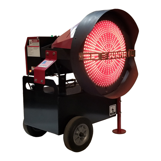
- Page 1 SERVICE MANUAL MODEL: SF-150 Service Manual SF-150 V1-1...
- Page 2 TABLE OF CONTENTS TOPIC PAGES TROUBLESHOOTING ..................... 1 - 4 HELPFUL IMAGES ....................5 - 10 SCHEMATICS AND PARTS BREAKDOWN ............11 - 19...
- Page 3 Main electrical power circuit Reset breaker breaker tripped Optional thermostat turned Turn thermostat up, check for down or improperly loose wires and test components installed/defective and replace if needed. Primary control safety Reset/test components, replace tripped/defective if needed Too much light showing on CAD Eliminate light to CAD cell/test cell/defective component Tip switch contacts are closed If plugged in, verify amber light is on. If not, it is a tip switch issue. Make sure SunFire unit is level. If level, tip switch may be defective and need replacement. 2. Attempts to fire but does not Low fuel Add fuel to tank establish a flame Contaminated fuel Drain fuel by removing plug on bottom of fuel tank, clean, retighten plug, and fill with clean fuel. Dirty fuel filter Clean or change filter Air bubble in fuel line Can sometimes be cleared by attempting to start 1 - 2 times. Or fix using the following process. Step 1: Open the burner control housing. Step 2: Loosen copper fuel line on the side of burner. Step 3: Hold a rag...
- Page 4 30 seconds CAD Cell is misaligned Test CAD cell by slightly adjusting position a few times. If issue pursists, see below. CAD cell is defective Test by using a jump wire from terminal F1 to terminal F2 on the primary control with the following process. Step 1: Hook jumper to F1. Step 2: Start unit and wait until flame is present. Step 3: Then immediately hook jump wire to F2. If unit continues to run after 1 minute, CAD cell is defective and needs to be repalced. WARNING: THIS IS FOR TESTING PURPOSES ONLY. FOR SAFETY, DO NOT CONTINTUE TO OPERATE USING JUMP WIRES. Burner settings may need Test burner. Remove burner adjustment. housing panel to access the burner. Start the SunFire and view the LED lights to the right of the burner primary control. If green light continues to blink, an adjustment may be needed. Adjust the top fuel pressure screw along with very slight adjustements to the air band until a correct adjustment is achieved and the green light stays solid green. Page 2 of 19...
- Page 5 Check power supply. If using a generator, run generator for 20 minutes and retry. If using an inverter, try a clean power supply. Try different power supply. 5. Black smoke or whisking Nozzle is dirty or clogged Replace nozzle Whisking - flames protrude Improper Air flow Adjust air band to 1.5 position through holes in dome face Improper fuel flow rate Adjust fuel flow rate Only after replacing nozzle 6. Runs briefly on a generator Generator is low on charge Run generator for 20 minutes, and shuts off then plug in SunFire unit and restart. 7. Amber lamp does not light Loose wires Check all power and tip-switch wires for cut or loose wires and secure or fix if needed. Tip switch is closed Level SunFire or replace tip switch. Bad Light Replace light Defective primary control circuit Replace primary control board 8. Won't fire Check temperature setting. Set thermostat to a higher If using a thermostat temperature if desired.
- Page 6 Symptom Possible Cause Corrective Action 9. No green light calling for heat Check the reset button Push and hold the reset button when unit is turned on If using thermostat See #8 above Defective Primary Replace primary 10. Bad flame Clogged Nozzle Soak Nozzle in parts cleaner/degreaser and blow it out. Or replace nozzle. Dirty/poor fuel drain fuel and add new clean fuel. Clogged/dirty filter Replace filter 11. Smoky flame Open transformer lid Make sure lid is closed Diesel treatment was used Add clean fuel to decrease treatment ratio, or drain all fuel and replace with new fuel and clean diesel treatment. Air flow is restricted Check air band and increase the air flow until smoke is no longer visible. Improper seal between fuel fliter Check the seal on the fuel filter and filter assembly. to make sure there are no obstructions between the filter and the filter assembly that could allow air to become mixed in the fuel, causing an improper fuel mixture.
- Page 7 HELPFUL SERVICE MANUAL IMAGES FIGURE 1-1 Burner Housing/Control Box Housing Screw Housing Screw FIGURE 1-2 Burner Pressure Valves High Pressure Valve Low Pressure Valve Note: Turn left for more fuel flow and right for less fuel. FIGURE 1-3 Igniter Assembly Retaining clamps Note: Loosen screws and turn clamps to open igniter assembly. Page 5 of 19...
- Page 8 FIGURE 2-1 CAD Cell FIGURE 2-2 Inside igniter box CAD Cell Electrode Igniters Note: If there is excessive dust while running the SunFire, the inside area of the igniter box should be inspected and cleaned periodically. Dust can build and causing the unit to turn of prematurely from dust build up on the CAD cell, which will shut the unit off for safety as the flame will not be visible and the electrodes may not receive a proper spark If igniters are dirty. If dirty, simply clean with cloth. Page 6 of 19...
- Page 9 FIGURE 3-1 Air Band Air Band Setting Note: The Air band should be set to approximately 1.25 - 1.5. Reducing the air band to a lower level will reduce the amount of airflow to the flame giving a higher concentration level of fuel that will raise the temperature of the SunFire. However, if reduced too low, it can cause whisking – see Figures 4-1&2 for examples. Reducing too low can become dangerous. This can easily be solved by increasing the amount of air within the flame by increasing the level of the air band. If the air band level is set too low, upon start up, you may notice some smoke and a more noticeable smell of diesel. FIGURE 4-1 Primary Control Self Test LED Note: Will blink for a second before the green flame sense light turns no. This simply let’s you know the unit has been turned on and will be calling for heat to produce a flame. Page 7 of 19...
- Page 10 FIGURE 4-2 Primary Control Green LED Note: If there are suspected issues with the flame because the unit has intermittently shut off, a green light that blinks indicates potential issues with the flame not running efficiently. Check symptoms and causes on previous pages. If green light remains solid, the flame is running correctly. FIGURE 4-3 Primary Control Red LED Note: If red “locked out” light is on, the control has failed to sense a flame after two attempts to fire and the reset button must be pressed before attempting to start again. When unit is turned on and does not fire on first attempts, this light will blink for 45 seconds. A 2 attempt will be made and if no flame is sensed, the light will turn solid until the reset button is pushed. Page 8 of 19...
- Page 11 FIGURE 5-1 Minor Whisking Small flames escaping dome face Note: It is recommended to increase the air band setting to approximately 1.50 and reduce the fuel flow on the high pressure valve if necessary. FIGURE 5-2 Severe Whisking Large flames escaping dome face. Warning: This is can be dangerous at these levels. It is recommended to immediately increase the air band setting to approximately 1.50 and reduce the fuel flow on the high pressure valve. Page 9 of 19...
- Page 12 FIGURE: 6-1 View Inside Cone of Nozzle/Flame Assembly Electrodes Air Flow Spinner Nozzle Burner Cone Note: It is important that the nozzle and electrodes remain free from excessive build-up. Clean if necessary or replace nozzle. It is critical to never run the unit without the burner cone in place to produce a proper flame. Page 10 of 19...
- Page 13 SCHEMATICS AND PARTS BREAKDOWN Page 11 of 19...
- Page 14 7202 NUT 3/8-16 HEX 29465 SUNFIRE LIFTING HANDLE ASSEMBL 34514 SCREW 3/8-16 X 1-1/2 HH ZN 29492 HINGE HANDLE BUMPER SELF ADHESIVE SF-150 34516 29469 SUNFIRE LEFT LOWER STRAP 34515 PIN QUICK RELEASE 6MM DIA 40M Page 12 of 19...
- Page 15 Page 13 of 19...
- Page 16 CAP GAUGE COMBO RAD HEAT 8" 29411 FTNG,JIC,ST,H,90EL06MJ-06MJ FILITER HEATER 29402 29407 FTNG,JIC,ST,H,90EL06MJ-08MP 91772A535 1/4-20 x 3/8" 29401 FILTER ASSEMBLY RADIANT HEATER SUCTION LINE HOSE 6" 29511 29484 RAD HEAT TUBE DRAW ASSEMBLY 29467 SUNFIRE TANK ASSEMBLY Page 14 of 19...
- Page 17 Page 15 of 19...
- Page 18 RADIANT HEATER BURNER CONE 29418 SPINNER RAD HTR VERSION 2 29459 FLANGE GASKET RAD HTR 33189 ELECTRIC IGNITER 33404 SF-150 PRIMARY 29544 SUNFIRE BURNER BLOWER WHEEL 9502 MOTOR 1/6HP 29505 ELECTRODES 29450 SWITCH TIP RAD HEATER 29437 CORD POWER RAD HTR 33168...
- Page 19 Page 17 of 19...
- Page 20 RADIANT HEATER TOP GASKET 29542 29508 SUNFIRE INSULATION INSULATION LYTHERM SF150 29499 DOME 29507 SUNFIRE SPUN DOME 29495 SF HEAT SHEILD 34116 10 X 5/8 HEX WASHER HEAD TEK Z 34399 3/8 SPLIT LOCK WASHER - SS 34010 3/8-16 BRASS HEX NUT...
- Page 21 Page 19 of 19...