Table of Contents
Advertisement
A1C-1405
Quick Reference
for Remote Countroller
Digital Inverter (DI)
Super Digital Inverter (SDI)
MiNi-Super Modular Multi System (MiNi-SMMS)
Super Modular Multi System (SMMS)
Super Modular Multi System-i (SMMS-i)
Super Heat Recover Multi System (SHRM)
Super Heat Recover Multi System-i (SHRM-i)
Printed in japan. Fed, 2013
TOMO
Advertisement
Table of Contents

Related Manuals for Toshiba RBC-EXW21E2


Summary of Contents for Toshiba RBC-EXW21E2
- Page 1 A1C-1405 Quick Reference for Remote Countroller Digital Inverter (DI) Super Digital Inverter (SDI) MiNi-Super Modular Multi System (MiNi-SMMS) Super Modular Multi System (SMMS) Super Modular Multi System-i (SMMS-i) Super Heat Recover Multi System (SHRM) Super Heat Recover Multi System-i (SHRM-i) Printed in japan.
-
Page 2: Table Of Contents
CONTENTS 1. Wired Remote Controller RBC-AMT31E, RBC-AMT32E ....................1 RBC-AMT21E ........................2 Part Name (RBC-AMT21E, RBC-AMT31E, RBC-AMT32E) ..........3 2. Simple Wired Remote Controlle RBC-AS21E, RBC-AS21E2 ....................5 Part Name (RBC-AS21E2) ....................6 3. Wireless Rmote Controller RBC-AX31U(W)-E, RBC-AX31U(WS)-E ................7 Part Name (RBC-AX31U(W)-E, RBC-AX31U(WS)-E) ............ -
Page 3: Wired Remote Controller
* Terminals A and B * Can not use the closed are non-polar end wire joint Basic wiring Remote controller Remote controller (Header) (Follower) (sold Combined weekly timer RBC-EXW21E2 separately) Type Name : RBC-AMT31E Part No. : 43166002 Remote controller wire Substitution : NO... - Page 4 Multiple wiring diagram (Max. 2 remote controllers can be set.) Remote controller address connector Master remote controller Remote controller Remote controller check Secondary remote controller Type Name : RBC-AMT21E Remote controller address Part No. : 4316V194 Substitution : NO Remote controller Remote controller (Header) (Follower)
-
Page 5: Rbc-Amt31E, Rbc-Amt32E
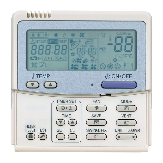
Part Name Display section RBC-AMT21E, RBC-AMT31E, RBC-AMT32E In the display example, all indicators are displayed for the explanation. In reality only, the selected contents are indicated. • When turning on the main power switch and leak breaker at the first time, flashes on the display part of the SETTING remote controller. -
Page 6: Rbc-Amt21E
Operation section Push each button to select a desired operation. • The details of the operation needs to be set up once, afterward, the air conditioner can be used by pushing (RBC-AMT21E) / button only. ON / OFF TEMP. ON / OFF TIMER SET MODE TIME... - Page 7 2. Simple WIred Remote Controller How to perform the wiring of the remote controller Connectiom diagram Remote controller Terminal block for remote controller wiring on the indoor unit Remote controller wire Wire from (Procured locally) Remote controller body W : White Connecting B : Black section...
-
Page 8: Part Name (Rbc-Amt21E, Rbc-Amt31E, Rbc-Amt32E)
Part Name • For Cooling Only type, are not displayed on LCD. • Max. 8 indoor units can be operated by a remote controller. • Once the operational items have been set, you can operate the previous condition by pushing the button only. - Page 9 3. WIreless Remote Contoroller How to wire the signal receiving Connection diagram Indoor unit Signal receving part Rmote controller White connection terminal block Black white Connection Connect the wires from the signal receiving part to the remote controller connection terminal block of the indoor unit.
-
Page 10: Part Name (Rbc-As21E2)
Part Name <RBC-AX31U(W)-E, RBC-AX31U(WS)-E> • When turning on the power supply for the first time, it will take up to 3 minutes before the [SET DATA] symbol will flash. This flashing display will last for around 1 minute. While this display is flashing, the model is being automatically confirmed. After the minute has passedand the [SET DATA] display has disappeared, you can then use the remote controller. - Page 11 < Hand Unit and Receiver > RBC-AX31U(W)-E (Except North America) RBC-AX31U(WS)-E (Except North America) Signal Receiving Part Name Example: Start/Stop button → RBC-AX31U(W)-E (White) RBC-AX31U(WS)-E Type Name : WH-H1JE2 (Black) Part No. : 43166006 Type Name : Receiver unit Part No. : Not assigned Emergency operation button NOte...
- Page 12 Sensor Unit wiring Indoor unit Sensor unit P.C. board Terminal block for CN001 remote controller White wiring Black 2P White One Indoor unit 2 remote controller Wireless Wired Type Name : RBC-AX22CE2 remote controller kit remote controller Part No. : Not assigned (Header) (Follower) Substitution...
- Page 13 Part Name Procedure Description Turn on power of the air conditioner. The operation is not accepted for 5 minutes when power has been turned on at first time after installation, and 1 minute when power has been turned on at the next time and after. After the specified time has passed, perform a test operation.
-
Page 14: Rbc-Ax22Ce, Rbc-Ax22Ce2
Part Name RBC-AX22CE, RBC-AX22CE2 Operation Manual • When turning on the power supply for the first time, it will take up to 3 minutes before the [SET DATA] symbol will flash. This flashing display will last for around 1 minute. While this display is flashing, the model is being automatically confirmed. - Page 15 < Hand Unit and Receiver > RBC-AX22CE2 (Except North America) Type Name : WH-H1JE2 Part No. : 43166006 Type Name : RBC-AX22CE2 Part No. : Not assigned Substitution : NO Type of Remote : Wireless Type Name : Integral receiver Reference : NO Part No.
- Page 16 19.5 4.4 x 9.4 long hole 4.4 x 5.4 long hole Type Name : TCB-AX21E Category Part No. : Not assigned Substitution : TCB-AX21E2 Type of Remote : Wireless remote controller kit MiNi-SMMS Reference : NO SMMS Product used : Light commercial SHRM Note SMMS-i...
-
Page 17: Tcb-Ax21E, Tcb-Ax21E2
Part Name TCB-AX21E, TCB-AX21E2 Operation Manual • When turning on the power supply for the first time, it will take up to 3 minutes before the [SET DATA] symbol will flash. This flashing display will last for around 1 minute. While this display is flashing, the model is being automatically confirmed. - Page 18 < Hand Unit and Receiver > TCB-AX21E2 (Except North America) Type Name : WH-H1JE2 Part No. : 43166006 Type Name : TCB-AX21E2 Part No. : Not assigned Substitution : NO Type Name : Receiver unit Type of Remote : Wireless Part No.
- Page 19 Central Remote Countroller for Schedule timer, Weekly timer, Central remote and ON-OFF Countroller...
-
Page 20: Schedule Timer
4. Schedule Timer Multiple wiring diagram Remote controller (inside, rear) DIP switch DIP switch DIP switch DIP switch Header remote Header remote Follower remote Follower remote control/scheduled control/timer control/scheduled control/no timer timer operation operation timer operation function Remote controller test run setup 1. -
Page 21: Part Name
Part Name All display are shown lighted only for the purposes of description 2 3 4 5 6 7 8 9 10 24 23 22 21 20 19 18 17 16 15 14 (Display section) Operation mode display Indoor temperature This indicates the mode of operation which is This appears when the intake temperature is currently selected. - Page 22 Numeric display Days of the week display This indicates the present clock time, program Special holiday operation time or timer execution time. This appears for a day of the week which has been Operation reservation set as a special holiday. This appears for the days of the week on which Day arrow programs have been set.
-
Page 23: Weekly Schedule Timer
5. Weekly schedule Timer Basic diagram 64 system central remote controller or ON-OFF controller Wiring specifications (1) Refrigerant system 1 Refrigerant system 3 (S-MMS) (S-MMS) Refrigerant system 2 (SDI/DI) Indoor unit Outdoor unit (Header unit) (Header unit) Outdoor unit U3 U4 U1 U2 U1 U2 U3 U4... -
Page 24: Part Name
Part Name A: PROGRAM button E: HOLIDAY button B: PROG. COPY buttons F: CANCEL button C: CLEAR button G: TIMER OFF button D: Setting buttons A: PROGRAM button Use to start setting programs and to enter program settings. B: PROG. COPY buttons Use to copy programs to specific days in a schedule. - Page 25 Display A B C A: Today’s day of the week Indicates today’s day of the week. B: Program schedule Appears under days that are scheduled for program operation. indication ( C: Holiday schedule indication Appears around scheduled holidays. D: ERROR indication Displayed when a mistake is made during timer setting.
-
Page 26: Central Remote Controller
6. Central Remote Controller Type Name : TCB-SC642TLE / TBC-SC642TLE2 Zone setting Part No. : Not assigned Substitution : TCB-SC642TLE2 Central control Remote contorol Type of Remote : Central remote controller ALL / Central ALL / Remote Reference : NO ZONE 1 ZONE 1 / Central ZONE 1 / Remote... -
Page 27: Part Name
Part Name A: ALL/ZONE/GR B: ZONE select C: GROUP select SELECT button button buttons F: Operation lamp D: ON button E: OFF button G: MODE button H: Temperature setting buttons M: SET button K: CHECK FAN SPEED button button N: CL button O: VENTILATION J: FLAP button button... - Page 28 Functions of buttons (Continued) D: ON button This button is for turning the selected air conditioner on. E: OFF button This button is for turning the selected air conditioner off. F: Operation lamp This lamp lights when the unit is turned on. G: MODE button Use this button to select one of the following five operations: (AUTO)
- Page 29 Functions of buttons (Continued) K: CHECK button This button is used only when servicing the air conditioner. Do not use the CHECK button for normal operation. CAUTION L: CENTRAL button Use this button to inhibit the individual operation by a remote controller CTRL as follows: 1: Individual ON/OFF operation is inhibited.
- Page 30 Display Description When the unit is in the heating standby mode, the indicator appears. The currently selected operation mode is displayed. The currently selected FAN SPEED, Airflow Direction and SWEEP settings are displayed. This indication appears when the filter needs cleaning. This indication appears only when an abnormality occurs within a unit.
- Page 31 How to start group operation To start group operation Stop Power Turn the power supply switch on more than 12 hours before starting operation. Press the SELECT button and select GROUP. Select the ZONE No. including the group to be operated by pressing ZONE button. Select the GROUP No.
- Page 32 How to start collective operation To start collective operation (ALL or ZONE) Stop Power Turn the power supply switch on 12 hours or more before starting operation. Press the SELECT button and select ALL or ZONE. In case of ZONE collective operation. Select the ZONE No.
-
Page 33: On-Off Controller
7. ON-OFF Controller Basic wiring Clamp for electrical wiring Type Name : TCB-CC163TLE / TCB-CC163TLE2 Part No. : Not assigned Connector (CN02) Substitution : TCB-CC163TLE2 for weekly timer Type of Remote : ON-OFF controller (optional) Reference : NO Product used : VRF Note CN02... - Page 34 Part Name ON/OFF button ALL OFF button ALL ON button A: ON/OFF button Press this to start up or stop an individual air conditioner. B: All ON button Press this to start up all the air conditioners at the same time. The indoor units which can be operated by the ON-OFF controller NOTE now start operating in sequence at intervals of 1 to 2 seconds.
- Page 35 8. Function Selecting Item (DN) Table 1. Setting data (CODE No. table (example)) Concealed Concealed Under High High Medium Item Setting data Factory-set value 4-way 2-way 1-way Slim duct duct duct high ceiling wall static duct static duct standard standard Filter sign lighting time Depending on Type Filter pollution level...
- Page 36 SDI (4Series example) Function selection item No. (DN) list Item Contents At shipment from factory 0000: None 0001: 150H Filter sign lighting time 0002: 2500H 0003: 5000H According to type 0004: 10000H 0005: Clogging sensor used 0000: Standard Filter stain level 0000: Standard 0001: Heavy stain (Half of standard time) 0001: No.1 unit...
-
Page 37: Mini-Smms
MiNi-SMMS Item Description At shipment Filter display delay timer 0000: None 0001: 150H According to type 0002: 2500H 0003: 5000H 0004: 10000H Dirty state of filter 0000: Standard 0000: Standard 0001: High degree of dirt (Half of standard time) Central control address 0001: No.1 unit 0064: No.64 unit 0099: Unfixed... - Page 38 Item Description At shipment High-ceiling adjustment 1-way air cassette (SH) 0000: Standard (Air flow selection) Value Type AP015, AP018 AP024 0000 Standard (factory default) 3.5 m or less 3.8 m or less 0001 High-ceiling (1) 4.0 m or less 4.0 m or less 0003 High-ceiling (3) 4.2 m or less...
-
Page 39: Smms
SMMS Item Description At shipment Filter sign lighting According to type time 0002 : 2500H 0003 : 5000H 0004 : 10000H Dirty state of filter 0000 : Standard 0001 : High degree of dirt 0000 : Standard (Half of standard time) Central control 0001 : No.1 unit 0064 : No.64 unit... -
Page 40: Smms-I
SMMS-i Item Description At shipment Filter display delay timer 0000: None 0001: 150H According to type 0002: 2500H 0003: 5000H 0004: 10000H Dirty state of filter 0000: Standard 0000: Standard 0001: High degree of dirt (Half of standard time) Central control address 0001: No.1 unit 0064: No.64 unit 0099: Unfixed... -
Page 41: Shrm
SHRM Item Description At shipment Filter sign lighting 0000 : None 0001 : 150H According to type time 0002 : 2500H 0003 : 5000H 0004 : 10000H Dirty state of filter 0000 : Standard 0001 : High degree of dirt 0000 : Standard (Half of standard time) Central control... -
Page 42: Shrm-I
SHRM-i Item Description At shipment Filter display delay timer 0000: None 0001: 150H According to type 0002: 2500H 0003: 5000H 0004: 10000H Dirty state of filter 0000: Standard 0000: Standard 0001: High degree of dirt (Half of standard time) Central control address 0001: No.1 unit 0064: No.64 unit 0099: Unfixed... - Page 43 Item Description At shipment High-ceiling adjustment 1-way cassette (SH) 0000: Standard (Air flow selection) Value Type AP015, AP018 AP024 0000 Standard (factory default) 3.5 m or less 3.8 m or less 0001 High-ceiling (1) 4.0 m or less 4.0 m or less 0003 High-ceiling (3) 4.2 m or less...
- Page 44 Codes (DN codes) for changing settings (Necessary for local advanced control) Item Description At shipment 40 Humidifier type setting 0000: No humidifier 0001: Humidifier Depends on the type Ventilation fan speed during 0000: Always LOW 0001: Operate at ventilation fan 0000: Always LOW nighttime heat purge speed set last time the...
-
Page 45: Rbc-Amt21E, Rbc-Amt31E, Rbc-Amt32E
9. Montor Function of Remote Controller Switch <Produre> (RBC-AMT21E) Push buttons simultaneously for 4 seconds or more to call up the service monitor mode. Pushing button returns the display to the normal display. < RBC-AMT21E > < RBC-AMT31E > < RBC-AMT32E > CODE No. -
Page 46: Indoor Unit Function Dn Code
10. Indoor Unit Function DN Code <RBC-AMT21E> <RBC-AMT31E> <RBC-AMT32E> CODE No. CODE No. DATA SETTING SET DATA SETTING UNIT No. UNIT No. R.C. R.C. TEMP. ON / OFF TEMP. ON / OFF TIMER SET MODE TIMER SET MODE TIME SWING/FIX VENT TIME SAVE... -
Page 47: Specific Indoor Unit Priority Mode
11. Specific Indoor Unit Priority Mode < Procedure > Using timer time buttons, select SET TEST Push button and temp. setup button ∗∗∗∗ DATA [ simultaneously for at least 4 seconds. After a while, the display flashes as shown in the Push button. -
Page 48: Smms, Mini-Smms, Smms-I, Shrm, Shrm-I Series
SMMS, MiNi-SMMS, SMMS-i, SHRM. SHRM-i Series <RBC-AMT21E> <RBC-AMT31E> <RBC-AMT32E> CODE No. CODE No. DATA SETTING SET DATA SETTING UNIT No. UNIT No. R.C. R.C. TEMP. ON / OFF TEMP. ON / OFF TIMER SET MODE TIMER SET MODE TIME SWING/FIX VENT TIME SAVE... - Page 49 TOSHIBA CARRIER CORPORATION 72-34 Horikawa-cho, Saiwai-ku, Kawasaki-shi, Kanagawa 212-8585, JAPAN Copyright © 1999 to 2013 TOSHIBA CARRIER CORPORATION, ALL Rights Reserved.