Advertisement
Quick Links
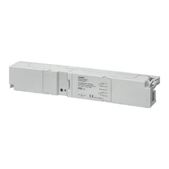
Switch actuator wave GE 561/01
Product- and Application Description
The switch actuator wave GE 561/01 is a 2-channel ac-
tuator with integrated KNX radio receiver/ transmitter
and a rating current of 2x16A for switching electric loads.
It can be controlled by up to 40 radio sensors that are
equipped with GAMMA wave radio technology and in-
corporated into a scene control with up to 16 scenes.
The switch actuator is connected to the 230-V network
and supplied with current via an integrated power sup-
ply. The connected loads are each switched via a relay
contact, it being adjustable whether the loads are to be
permanently switched on or off (normal operation) or
whether the actuator should function in time-switch op-
eration with an adjustable on-period from 1 to 60 min-
utes.
In the event of a failure of operational power the switch
state of both relays is maintained.
The GE device is embodied in an elongated design and
is suitable for installation in housing or under covers.
The switch actuator is put into operation without addi-
tional auxiliaries via a pushbutton installed on the top of
the device and an LED to display the operation condi-
tions in the "special function" operating mode.
The "Special Function" operating mode includes the fol-
lowing functions:
•
Connecting radio sensors with the function switching
"ON/OFF" or scene
•
Activating/deactivating the time switch function
•
Clearing connections to radio sensors
•
Resetting the device to the supplied state
Siemens AG
Automation and Drives Group
Electrical Installation Technology
P.O. Box 10 09 53, D-93009 Regensburg
Technical Specifications
Frequency band
•
868 MHz (transmission is not susceptible to interfer-
ence; frequency band reserved for system and secu-
rity applications)
Range of radio control
•
Approx. 100 m in clear area
Power supply
•
230V power supply via terminals 2 (L1) and 3 (N)
•
Rated voltage: AC 230V, 50 Hz
•
Protection via 16A circuit-breaker,
characteristic B or C required
Control elements
•
1 pushbutton: to switch between different operation
and commissioning conditions
Display elements
•
1 red LED: to display the operation conditions and
settings during commissioning
Outputs
•
Number: 2 (relay contacts)
•
Rated voltage: AC 230V
•
Rated current: 16A at cos phi = 1
Connections
•
5 screw terminals for power supply and load supply;
wire-stripping length approx. 7 ... 8 mm
•
The following conductors or cross sections are per-
missible:
- 0.5 to 4 mm
- 0.5 to 2,5 mm
Mechanical specifications
•
Housing: plastic
•
Dimensions: device installation,
42 x 32 x 274.5 mm (W x H x L)
•
Weight: approx. 200 g
•
Fire load: approx. 5500 kJ
Electrical safety
•
Pollution degree (according to IEC 60664-1): 2
•
Protection (according to EN 60529): IP 20
•
Overvoltage category (according to IEC 60664- 1) III
•
Device complies with EN 60669-2-1
•
Relays with µ contact
wave GE 561/01, 6 pages
© Siemens AG 2007
Subject to change without prior notice
Technical Product Information
5WG3 561-4AB01
2
single-wire
2
finely stranded
Update: http://www.siemens.de/gamma
GAMMA wave
February 2007
Technical Manual
2.20.8.1/1
Advertisement

Related Manuals for Siemens GAMMA wave GE 561/01


Summary of Contents for Siemens GAMMA wave GE 561/01
- Page 1 Relays with µ contact Siemens AG wave GE 561/01, 6 pages Technical Manual Automation and Drives Group © Siemens AG 2007 Electrical Installation Technology Update: http://www.siemens.de/gamma P.O. Box 10 09 53, D-93009 Regensburg Subject to change without prior notice 2.20.8.1/1...
-
Page 2: Electromagnetic Compatibility
R&TTE regulations General description The device is attached with two screws 4 mm ∅ (bore SIEMENS AG hereby states that the switch actuator spacing 251 mm central). wave GE 561/01 is in compliance with the basic re- quirements and the other relevant provisions of Regula- Opening the terminal chamber (Diagram B) tion 1999/5/EC. - Page 3 5 ––► Load output channel B 274,5 Siemens AG wave GE 561/01, 6 pages Technical Manual Automation and Drives Group © Siemens AG 2007 Electrical Installation Technology Update: http://www.siemens.de/gamma P.O. Box 10 09 53, D-93009 Regensburg Subject to change without prior notice 2.20.8.1/3...
- Page 4 “special function” operating mode. Technical Manual wave GE 561/01, 6 pages Siemens AG Automation and Drives Group © Siemens AG 2007 Update: http://www.siemens.de/gamma Electrical Installation Technology Subject to change without prior notice P.O. Box 10 09 53, D-93009 Regensburg...
- Page 5 A” or “special function channel B“. Siemens AG wave GE 561/01, 6 pages Technical Manual Automation and Drives Group © Siemens AG 2007 Electrical Installation Technology Update: http://www.siemens.de/gamma P.O. Box 10 09 53, D-93009 Regensburg Subject to change without prior notice...
-
Page 6: General Notes
Technical Manual wave GE 561/01, 6 pages Siemens AG Automation and Drives Group © Siemens AG 2007 Update: http://www.siemens.de/gamma Electrical Installation Technology Subject to change without prior notice P.O. Box 10 09 53, D-93009 Regensburg 2.20.8.1/6...