Table of Contents
Advertisement
Quick Links
Advertisement
Table of Contents

Related Manuals for Pride Mobility GC3


Summary of Contents for Pride Mobility GC3
- Page 1 Basic Operation Instructions Controller ™...
- Page 2 NOTE: This product is compliant with WEEE, RoHS, and REACH directives and requirements. NOTE: This product meets IPX4 classification (IEC 60529). NOTE: The GC3 Controller and its components are not made with natural rubber latex. Consult with the manufacturer regarding any after-market accessories.
-
Page 3: Table Of Contents
Table of Contents Label Information ..........................4 GC3 Controller ............................ 5 Precautionary Guidelines ........................5 Operating the GC3 Controller ......................7 Controller Communication Connector .................... 10 Lock Mode ............................10 Sleep Mode ............................10 Thermal Rollback ..........................10 Fault Codes ............................11 Care and Maintenance ........................ -
Page 4: Label Information
Label Information Product Safety Symbols The symbols below are used on the controller to identify warnings, mandatory actions, and prohibited actions. It is very important for you to read and understand them completely. Read and follow the information in the owner’s manual. Avoid exposure to rain, snow, ice, salt, or standing water whenever possible. -
Page 5: Gc3 Controller
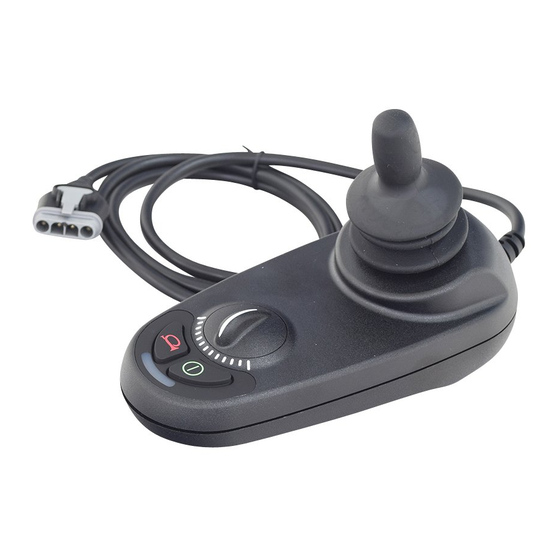
Precautionary Guidelines Before operating the GC3 controller, please read the following. These guidelines are provided for your benefit and will aid you in the safe operation of the control system. Turn off the power to the controller when transferring to or from your power chair. - Page 6 GC3 Controller Features Figure 1 provides information on the GC3 components and connections. Use this diagram to familiarize yourself with the function and location of each component before using the GC3 controller. The following functions are available with the GC3 Controller: ...
-
Page 7: Operating The Gc3 Controller
Operating the GC3 Controller The GC3 controller is used to operate your power chair and all of its components. The GC3 controller system consists of (see figure 2): 1. Joystick 2. Control panel 3. Joystick module 4. Off-board charging/programming socket 5. - Page 8 BATTERY CONDITION METER ON/OFF KEY HORN KEY SPEED DIAL Figure 3. Control Panel Control Panel The control panel is located directly in front of the joystick. It contains keys and a dial that you will use to control your power chair. See figure 3. On/Off Key The on/off key turns the system on and off.
- Page 9 Provider for more information. Speed Dial The GC3 controller provides a speed dial to control the speed of the power chair. See figure 3. To change the speed: 1. Push the on/off key to power on the chair and the controller.
-
Page 10: Controller Communication Connector
Sleep Mode Your GC3 controller has a sleep mode feature. Sleep mode is a built-in circuit that automatically shuts off the main power if the joystick is not moved in any direction for a period of time predetermined by the controller program. -
Page 11: Fault Codes
Fault Codes The battery condition meter will flash fault codes when the controller system detects an abnormal condition in the electrical system. All of the battery condition meter LEDs will flash a number of times quickly, then pause, then flash again. The battery condition meter will continue to flash the fault codes until the problem is fixed. - Page 16 B.V. (Authorised EU Representative) 182 Susquehanna Avenue De Zwaan 3 Exeter, PA 18643-2694 1601 MS Enkhuizen Canada The Netherlands 5096 South Service Road www.pride-mobility.nl Beamsville, Ontario L0R 1B3 Italy Australia Via del Progresso-ang. Via del Lavoro 20-24 Apollo Drive Loc. Prato della Corte Hallam, Victoria 3803 00065 Fiano Romano (RM) www.pridemobility.com.au...