Table of Contents
Advertisement
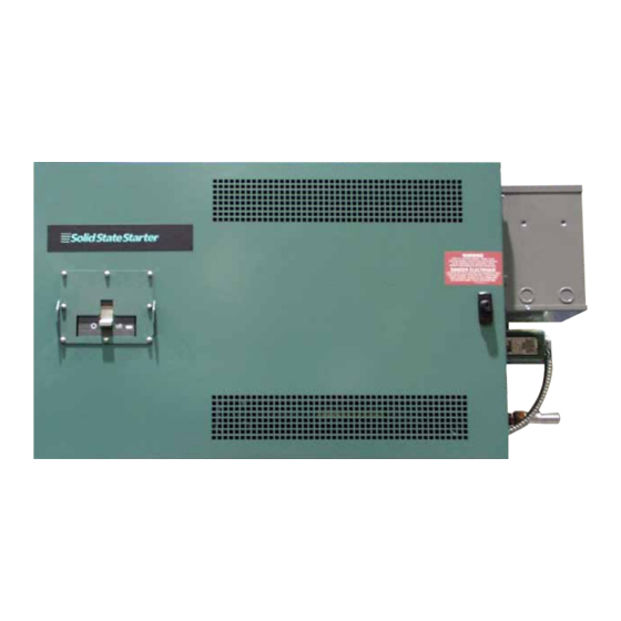
LIQUID COOLED
SOLID STATE STARTER
OPERATION
Supersedes: 160.00-O2 (611)
Form 160.00-O2 (419)
MODELS SSS 7L-B, 14L-B, 26L-B, 33L-B
7LK-B, 14LK-B, 26LK-B, 33LK-B
(STYLE B)
00282VIP
NOTE
Unless otherwise noted, information in this instruction
is applicable to all style starters of the same size.
Example: 26L-B and 26LK-B
Issue Date:
April 30, 2019
Advertisement
Table of Contents

Summary of Contents for York SSS 7L-B
- Page 1 LIQUID COOLED SOLID STATE STARTER OPERATION Supersedes: 160.00-O2 (611) Form 160.00-O2 (419) MODELS SSS 7L-B, 14L-B, 26L-B, 33L-B 7LK-B, 14LK-B, 26LK-B, 33LK-B (STYLE B) 00282VIP NOTE Unless otherwise noted, information in this instruction is applicable to all style starters of the same size.
- Page 2 FORM 160.00-O2 ISSUE DATE: 04/30/2019 IMPORTANT! READ BEFORE PROCEEDING! GENERAL SAFETY GUIDELINES This equipment is a relatively complicated apparatus. which it is situated, as well as severe personal injury or During rigging, installation, operation, maintenance, death to themselves and people at the site. or service, individuals may be exposed to certain com- This document is intended for use by owner-authorized ponents or conditions including, but not limited to:...
- Page 3 FORM 160.00-O2 ISSUE DATE: 04/30/2019 CHANGEABILITY OF THIS DOCUMENT In complying with Johnson Controls’ policy for con- regarding the applicability of these documents, rig- tinuous product improvement, the information con- ging, lifting, and operating/service personnel should tained in this document is subject to change without verify whether the equipment has been modified and notice.
- Page 4 FORM 160.00-O2 ISSUE DATE: 04/30/2019 THIS PAGE INTENTIONALLY LEFT BLANK JOHNSON CONTROLS...
-
Page 5: Table Of Contents
FORM 160.00-O2 ISSUE DATE: 04/30/2019 TABLE OF CONTENTS SECTION 1 – THEORY OF OPERATION .........................9 Style B Liquid Cooled Solid State Starter Overview ..................9 General ................................11 System Microprocessors ..........................11 Solid State Starter Cooling Loop ........................13 Electrical Conditions ............................14 Motor Protection ............................. - Page 6 FORM 160.00-O2 ISSUE DATE: 04/30/2019 TABLE OF CONTENTS (CONT’D) SECTION 8 – MAINTENANCE AND TROUBLESHOOTING .................35 Manually Running The Closed Loop Coolant Pump ..................35 Coolant Maintenance ............................. 35 Troubleshooting The Closed Loop Coolant Pump ..................35 Troubleshooting Processes ..........................35 Verify Shorted SCR ............................
- Page 7 FORM 160.00-O2 ISSUE DATE: 04/30/2019 LIST OF FIGURES FIGURE 1 - LCSSS – Front View, Exterior .......................9 FIGURE 2 - LCSSS – Basic Block Diagram ......................11 FIGURE 3 - LCSSS – Rear View, Exterior ......................12 FIGURE 4 - LCSSS – Interior, Connection Section - Fuses And Logic/Trigger Board ........... 15 FIGURE 5 - LCSSS –...
- Page 8 FORM 160.00-O2 ISSUE DATE: 04/30/2019 THIS PAGE INTENTIONALLY LEFT BLANK JOHNSON CONTROLS...
-
Page 9: Section 1 - Theory Of Operation
The Style B Liquid Cooled Solid State Starter (LC- this product. Due to the integration of the Solid State SSS) is a state of the art, soft start for YORK com- Starter with the YORK OptiView Control Center, an pressor motors. New features include a combined... -
Page 10: Table 1 - Style B Lcsss Variations
FORM 160.00-O2 SECTION 1 – THEORY OF OPERATION ISSUE DATE: 04/30/2019 TABLE 1 - STYLE B LCSSS VARIATIONS LINE VOLTAGE PART NUMBER FOR A MODEL APPLICATION (VAC) STARTER WITH LUG KIT 7L-40 371-02506-102 7L-46 440 / 460 / 480 371-02506-103 7L-58 550 / 575 / 600 371-02506-104... -
Page 11: General
FORM 160.00-O2 SECTION 1 – THEORY OF OPERATION ISSUE DATE: 04/30/2019 In order to reduce size of the starter, the cooling GENERAL to the SCR assemblies is provided by a water-to- The Style B LCSSS provides a soft continuous-current water heat exchanger between the chiller condenser start for the compressor motor. -
Page 12: Figure 3 - Lcsss - Rear View, Exterior
FORM 160.00-O2 SECTION 1 – THEORY OF OPERATION ISSUE DATE: 04/30/2019 The main system microprocessor performs many func- to a digital driver chip and then to six optical couplers, tions. It provides the serial communications link be- one for each SCR. tween the Logic/Trigger Board, and the Micro Board The optical couplers are the first stage of the trigger in the OptiView Control Center. -
Page 13: Solid State Starter Cooling Loop
FORM 160.00-O2 SECTION 1 – THEORY OF OPERATION ISSUE DATE: 04/30/2019 water is forced through the heat exchanger by the pres- SOLID STATE STARTER COOLING LOOP sure differential across the condenser shell input and The SCRs in the LCSSS generate heat during normal output. -
Page 14: Electrical Conditions
FORM 160.00-O2 SECTION 1 – THEORY OF OPERATION ISSUE DATE: 04/30/2019 ELECTRICAL CONDITIONS MOTOR PROTECTION Proper starter operation requires that all phases of the Compressor motor protection circuits are provided on AC power line voltage are present, and in the correct the Logic/Trigger Board. -
Page 15: Section 2 - System Architecture
FORM 160.00-O2 ISSUE DATE: 04/30/2019 SECTION 2 – SYSTEM ARCHITECTURE The following LCSSS components are located in an A control power transformer is attached to the side of enclosure mounted to the compressor motor terminal the starter enclosure. This supplies 115 VAC control box. -
Page 16: Figure 5 - Lcsss - Interior, Power Section
FORM 160.00-O2 SECTION 2 – SYSTEM ARCHITECTURE ISSUE DATE: 04/30/2019 OUTPUT CURRENT TRANSFORMERS GATE LEADS GATE LEADS HEATSINK INPUT ASSEMBLIES BARS 00286VIP FIGURE 5 - LCSSS – INTERIOR, POWER SECTION JOHNSON CONTROLS... -
Page 17: Section 3 - Logic/Trigger Board
FORM 160.00-O2 ISSUE DATE: 04/30/2019 SECTION 3 – LOGIC/TRIGGER BOARD GENERAL INFORMATION CURRENT SCALING The new Logic/Trigger Board is basically an integra- In order for the motor current to be properly scaled tion of the functions in the Logic and Trigger Board by the Micro Board, the Logic/Trigger Board sends a in the Style A LCSSS. -
Page 18: Logic/Trigger Board Indicator Leds
FORM 160.00-O2 SECTION 3 – LOGIC/TRIGGER BOARD ISSUE DATE: 04/30/2019 factorily, and the contacts will open when the LCSSS LOGIC/TRIGGER BOARD INDICATOR LEDS initiates a Cycling or Safety shutdown. These contacts The Logic/Trigger Board contains only two LEDs. will remain open until the cause of the shutdown has Since all of the shutdown messages are displayed on been rectified. -
Page 19: Table 4 - Logic/Trigger Board Inputs And Outputs
FORM 160.00-O2 SECTION 3 – LOGIC/TRIGGER BOARD ISSUE DATE: 04/30/2019 TABLE 4 - LOGIC/TRIGGER BOARD INPUTS AND OUTPUTS JUMPER DESCRIPTION J1 PINS Phase “A” motor current input from current transformer (2T). AC voltage is read with digital voltmeter across resistor R76 (top of R76 is GND). Voltage read should be: J1-1 and 2 RMS Motor Current = (AC Voltage Measured/3.01) x CT RATIO... -
Page 20: Figure 7 - Logic/Trigger Board Pin Location Diagram
FORM 160.00-O2 SECTION 3 – LOGIC/TRIGGER BOARD ISSUE DATE: 04/30/2019 TABLE 4 - LOGIC/TRIGGER BOARD INPUTS AND OUTPUTS JUMPER DESCRIPTION J11-PINS J11-1 Phase “C” Negative SCR gate output. .55-2 VDC as measured to J11-2 when the starter is running. J11-2 Phase “C”... -
Page 21: Section 4 - Safety Shutdowns
FORM 160.00-O2 ISSUE DATE: 04/30/2019 SECTION 4 – SAFETY SHUTDOWNS GENERAL INFORMATION Possible Problems • Verify that the programmed FLA is correct on the Whenever a Safety Shutdown is generated by the Log- OptiView Control Center. ic/Trigger Board a series of events will occur: •... -
Page 22: Open Scr
FORM 160.00-O2 SECTION 4 – SAFETY SHUTDOWNS ISSUE DATE: 04/30/2019 Possible Problems OUTPUT CURRENT IMBALANCE • Check for a shorted SCR. This shutdown will become active after the starter has been running for 45 seconds, and when the highest • Disconnect the motor and test for shorts phase to of the three motor currents exceeds 80% of the pro- ground, and phase to phase. -
Page 23: Shorted Scr
FORM 160.00-O2 SECTION 4 – SAFETY SHUTDOWNS ISSUE DATE: 04/30/2019 The YR chiller has a “MOTOR – PHASE ROTA- age for that phase is approximately 90% of the selected TION” fault. This is not a fault of the LCSSS. This input voltage range a Safety shutdown will occur. - Page 24 FORM 160.00-O2 ISSUE DATE: 04/30/2019 THIS PAGE INTENTIONALLY LEFT BLANK JOHNSON CONTROLS...
-
Page 25: Section 5 - Cycling Shutdowns
FORM 160.00-O2 ISSUE DATE: 04/30/2019 SECTION 5 – CYCLING SHUTDOWNS GENERAL INFORMATION chart below. If the input voltage exceeds the shutdown threshold for 20 continuous seconds, then a Cycling Whenever a Cycling Shutdown is generated by the shutdown will occur. This shutdown is disabled for the Logic/Trigger Board, a series of events will occur. -
Page 26: Invalid Current Scale
FORM 160.00-O2 SECTION 5 – CYCLING SHUTDOWNS ISSUE DATE: 04/30/2019 Possible Problems LOGIC BOARD PROCESSOR • Verify the communication cable between the A watchdog type of system is used to determine if OptiView Control Center and the Logic/Trigger the main system microprocessor and the DSP are still Board. -
Page 27: Phase Locked Loop
FORM 160.00-O2 SECTION 5 – CYCLING SHUTDOWNS ISSUE DATE: 04/30/2019 shutdown will occur. This shutdown is disabled for the Possible Problems first 20 seconds of the starter run, to prevent nuisance • Although this circuit is very fast, storms or power shutdowns from heavily loaded transformers. -
Page 28: Power Fault
FORM 160.00-O2 SECTION 5 – CYCLING SHUTDOWNS ISSUE DATE: 04/30/2019 is opto-coupled, and then sent to the main system mi- TABLE 7 - PHASE LOSS croprocessor, where it is compared with a run signal INPUT VOLTAGE RANGE SHUTDOWN VALUE sent from the OptiView Control Center via the serial OF THE LCSSS communications link (software signal). -
Page 29: Stop Contacts Open
FORM 160.00-O2 SECTION 5 – CYCLING SHUTDOWNS ISSUE DATE: 04/30/2019 • Verify the communication cable between the STOP CONTACTS OPEN OptiView Control Center and the Logic/Trigger Whenever a shutdown occurs, the K1 relay de-energiz- Board. es and the contacts open on the Logic/Trigger Board. If the K1 contacts open, and no fault is detected in the •... - Page 30 FORM 160.00-O2 ISSUE DATE: 04/30/2019 THIS PAGE INTENTIONALLY LEFT BLANK JOHNSON CONTROLS...
-
Page 31: Section 6 - Start Inhibit
FORM 160.00-O2 ISSUE DATE: 04/30/2019 SECTION 6 – START INHIBIT HIGH TEMPERATURE To minimize the time it takes to cool down the SCRs, and allow the chiller to restart sooner if the anti-recy- During the ramp up period, when starting current is cle has timed out, a condenser water pump control has being conducted to the motor, the internal die of the been added to the OptiView Control Center software. -
Page 32: Table 8 - Lcsss Thermistor Characteristics
FORM 160.00-O2 SECTION 6 – START INHIBIT ISSUE DATE: 04/30/2019 TABLE 8 - LCSSS THERMISTOR CHARACTERISTICS TEMP °F TEMP °C R-THERMISTOR V-THERMISTOR** V-INPUT*** NOMINAL NOMINAL IN OHMS* 21.11 11882 3.44 1.06 23.89 10502 3.33 1.16 26.67 9299 3.21 1.26 29.44 8253 3.09 1.37... -
Page 33: Section 7 - Start-Up Instructions
The Style B LCSSS is shipped with tach to starter bus bars. This includes nuts, bolts, a 50/50 mix of Propylene Glycol and YORK Corro- washers, hand tools, test equipment, metal shav- sion Inhibitor. This type of coolant is being used to ings etc. - Page 34 Fill Procedure 5. Verify that all of the air has been worked out of 1. Fill the coolant reservoir with YORK Coolant un- the coolant. If not, continue to run the coolant til the level is 1/2 inch from the top of the coolant pump, and add YORK coolant as required.
-
Page 35: Section 8 - Maintenance And Troubleshooting
FORM 160.00-O2 ISSUE DATE: 04/30/2019 SECTION 8 – MAINTENANCE AND TROUBLESHOOTING MANUALLY RUNNING THE CLOSED LOOP Do Not Reuse Coolant COOLANT PUMP In the event that the coolant must be removed to fa- cilitate a repair to the LCSSS. All of the coolant must The Style B LCSSS is now controlled by a micropro- be drained, discarded, and new coolant installed. -
Page 36: Verify Shorted Scr
FORM 160.00-O2 SECTION 8 – MAINTENANCE AND TROUBLESHOOTING ISSUE DATE: 04/30/2019 the service technician must understand the system in- 4. Insert the ohm meter probes into the connector. terface, and be able to utilize system wiring diagrams The meter should display a good value of 10 – 20 to follow signal flow throughout the system. -
Page 37: Verify Real Phase Current Imbalance
FORM 160.00-O2 SECTION 8 – MAINTENANCE AND TROUBLESHOOTING ISSUE DATE: 04/30/2019 multiply by 100. The result is the percentage VERIFY REAL PHASE CURRENT IMBALANCE phase imbalance for that phase. Depending on the load of the motor a value of 1.5% can cause a cur- The starter cabinet contains high voltages rent imbalance of 15%. -
Page 38: Verify False Phase Current Imbalance
FORM 160.00-O2 SECTION 8 – MAINTENANCE AND TROUBLESHOOTING ISSUE DATE: 04/30/2019 8. Reconnect the J1 connector. 8. After the chiller has been running for one min- ute, measure the voltage across the SCR. The 9. If this is not the source of the problem, continue. voltage should measure between .70 –... -
Page 39: Installing Scr Assemblies
FORM 160.00-O2 SECTION 8 – MAINTENANCE AND TROUBLESHOOTING ISSUE DATE: 04/30/2019 COOLANT PUMP CONDUIT PUMP CONDUIT ASSEMBLY (1 OF 3) RESISTOR CAPACITOR INPUT BUS BAR ASSEMBLY 00286VIP FIGURE 9 - LCSSS – POWER COMPONENTS 10. Remove the four SCR/heatsink assembly mount- pad and coat with a thin film of thermal joint com- ing nuts from the mounting studs and remove the pound (013-02880-000) before attaching the in-... - Page 40 1-800-524-1330 5000 Renaissance Drive, New Freedom, Pennsylvania USA 17349 Subject to change without notice. Printed in USA www.johnsoncontrols.com Copyright © by Johnson Controls 2019 ALL RIGHTS RESERVED Form 160.00-O2 (419) Issue Date: April 30, 2019 Supersedes: 160.00-O2 (611)