Table of Contents
Advertisement
Quick Links
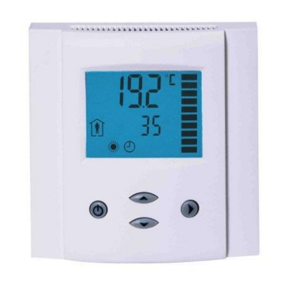
Programmable operation terminal for MODBUS
OPA2-MOD
Application
The operation terminal controls typically a single room control unit. The device measures room temperature and humidity
(for –H type) through integrated sensors. Two additional digital inputs may be configured for window contact, key
switches or motion detectors. The operation mode may then be controlled based on these inputs. An external temperature
may be measured through the additional temperature input. This may be useful for underfloor heating, sensor averaging
for large rooms, outdoor temperatures etc.
The operation terminal communicates through a galvanically isolated RS485 interface via the MODBUS protocol in slave
mode.
Ordering
Model
Item#
OPA2-MOD
40-50 0014
OPA2-MOD-H
40-50 0053
Supported Modbus commands:
-
03 (0x03): Read multiple registers
-
06 (0x06): Write single register
-
16 (0x10): Write multiple registers
Commands 03 and 16 can handle up to 32 registers. The Modbus slave transmits the values as signed 16 bit integers with
one digit below the decimal point. This results in the following range: -9999.9 to 9999.9
In an event of an out-of-range command addressing or an unsupported command, the Modbus slave responds with an
exception message according to the Modbus specification.
Dimensions [mm](in)
Doc: 70-00-0290, V1.0 R0, Date: 20160208
Subject to alteration
Features
Display
RT
yes
1
yes
1
88 (3.5)
LCD display with backlight four keys
Internal temperature sensor
With –H model, internal humidity sensor
1 external temperature input
2 digital inputs, which can be configured for window/door contacts
or motion detectors.
Up to 5 zones may be handled by one operation terminal
Detailed configuration possible
RS485 2-wire MODBUS standard in accordance to EIA/TIA 485
Slave type of communication
Galvanic isolated bus connection
Flush mounted on standard EU/UK/CH installation box
DI
rH
Modbus communication module with one internal
2
-
temperature sensor and one external temperature
input plus two binary inputs.
As above with internal humidity sensor 3%
2
1
accuracy.
32
21
(1.2)
(0.8)
© Vector Controls GmbH, Switzerland
OPA2-MOD(-H)
Description
Page 1
Advertisement
Table of Contents

Related Manuals for Vector OPA2-MOD

Summary of Contents for Vector OPA2-MOD
- Page 1 In an event of an out-of-range command addressing or an unsupported command, the Modbus slave responds with an exception message according to the Modbus specification. Dimensions [mm](in) 88 (3.5) (1.2) (0.8) Doc: 70-00-0290, V1.0 R0, Date: 20160208 © Vector Controls GmbH, Switzerland Page 1 Subject to alteration...
-
Page 2: Technical Specifications
Front part: 88 x 88 x 21 mm (3.5” x 3.5” x 0.8”) Back part: ø 58 x 32 mm (ø 2.3” x 1.3”) Weight (including package) 240g (8.47 oz) Doc: 70-00-0290, V1.0 R0, Date: 20160208 © Vector Controls GmbH, Switzerland Page 2 Subject to alteration... -
Page 3: Installation
This screw is located on the front lower side of the unit. There is no need to tighten the screw too much. Doc: 70-00-0290, V1.0 R0, Date: 20160208 © Vector Controls GmbH, Switzerland Page 3 Subject to alteration... -
Page 4: Display And Operation
The selected sensor is damaged or missing. The selected sensor is not enabled The change of setpoint or operation mode is disabled or the remote disable function is active. Doc: 70-00-0290, V1.0 R0, Date: 20160208 © Vector Controls GmbH, Switzerland Page 4 Subject to alteration... -
Page 5: Configuration Parameters
OPA2-MOD(-H) Configuration Configuration parameters The OPA2-MOD can be fine-tuned with a simple parameter setup routine. The parameters can be changed on the unit without the need of additional equipment. Access to parameters The parameters can be changed as follows: Press UP/DOWN buttons simultaneously for three seconds. The version is now shown in the large digits, the subversion is shown below. -
Page 6: Register Definitions
This is used for key card switches or motion detectors connected to digital inputs. This function is controlled with registers 10300/10400. Doc: 70-00-0290, V1.0 R0, Date: 20160208 © Vector Controls GmbH, Switzerland Page 6 Subject to alteration... - Page 7 A flag to define where the alarm text shall be displayed 0 = nowhere 1 = large digits 2 = small digits 2017 Show time symbol (0) 2018 Show manual override symbol (0) Doc: 70-00-0290, V1.0 R0, Date: 20160208 © Vector Controls GmbH, Switzerland Page 7 Subject to alteration...
- Page 8 3005 8bit (ASCII) Text string OFF letter 2: 3006 8bit (ASCII) Text string OFF letter 3: 3007 8bit (ASCII) Text string OFF letter 4: Doc: 70-00-0290, V1.0 R0, Date: 20160208 © Vector Controls GmbH, Switzerland Page 8 Subject to alteration...
-
Page 9: Display In Idle Mode
4004 8bit (ASCII) text string ON letter 2: 4005 8bit (ASCII) text string ON letter 3: 4006 8bit (ASCII) text string ON letter 4: Doc: 70-00-0290, V1.0 R0, Date: 20160208 © Vector Controls GmbH, Switzerland Page 9 Subject to alteration... -
Page 10: Display Zone
Group 2 = 6000 – 6013 Group 3 = 7000 – 7013 Group 4 = 8000 – 8013 Group 5 = 9000 – 9013 Doc: 70-00-0290, V1.0 R0, Date: 20160208 © Vector Controls GmbH, Switzerland Page 10 Subject to alteration... -
Page 11: Input Configuration
Once the input is opened it will switch to unoccupied mode after the delay defined with address 1024 (CP20) has expired. The delay is defined in minutes. Doc: 70-00-0290, V1.0 R0, Date: 20160208 © Vector Controls GmbH, Switzerland Page 11 Subject to alteration... - Page 12 FAN string 4 character 3 (“N”) 11015 byte FAN string 4 character 4 (“3”) Reduced ASCII table for display of characters ASCII Item ASCII Item ASCII Item (space) Doc: 70-00-0290, V1.0 R0, Date: 20160208 © Vector Controls GmbH, Switzerland Page 12 Subject to alteration...