Table of Contents
Advertisement
O
M
PERATOR'S
ANUAL
Models
31AE553F401
31AE573H401
IMPORTANT: READ SAFETY RULES AND INSTRUCTIONS CAREFULLY
Warning:
This unit is equipped with an internal combustion engine and should not be used on or near any unimproved forest-
covered, brush-covered or grass-covered land unless the engine's exhaust system is equipped with a spark arrester meeting
applicable local or state laws (if any). If a spark arrester is used, it should be maintained in effective working order by the operator.
In the State of California the above is required by law (Section 4442 of the California Public Resources Code). Other states may have
similar laws. Federal laws apply on federal lands. A spark arrester for the muffler is available through your nearest engine authorized
service dealer or contact the service department, P.O. Box 368022 Cleveland, Ohio 44136-9722.
MTD PRODUCTS INC. P.O. BOX 368022 CLEVELAND, OHIO 44136-9722
PRINTED IN U.S.A.
FORM NO. 770-10028
(7/98)
Advertisement
Table of Contents

Related Manuals for Yard-Man 31AE553F401


Summary of Contents for Yard-Man 31AE553F401
- Page 1 PERATOR’S ANUAL Models 31AE553F401 31AE573H401 IMPORTANT: READ SAFETY RULES AND INSTRUCTIONS CAREFULLY Warning: This unit is equipped with an internal combustion engine and should not be used on or near any unimproved forest- covered, brush-covered or grass-covered land unless the engine’s exhaust system is equipped with a spark arrester meeting applicable local or state laws (if any).
-
Page 2: Section 1: Important Safe Operation Practices
SECTION 1: IMPORTANT SAFE OPERATION PRACTICES WARNING: THIS SYMBOL POINTS OUT IMPORTANT SAFETY INSTRUCTIONS WHICH, IF NOT FOLLOWED, COULD ENDANGER THE PERSONAL SAFETY AND/OR PROPERTY OF YOURSELF AND OTHERS. READ AND FOLLOW ALL INSTRUCTIONS IN THIS MANUAL BEFORE ATTEMPTING TO OPERATE YOUR SNOW THROWER. FAILURE TO COMPLY WITH THESE INSTRUCTIONS MAY RESULT IN PERSONAL INJURY. -
Page 3: Maintenance And Storage
repairs, adjustments, or inspections. Never place your hand in the discharge or collector openings. Use a stick or wooden broom handle to unclog the discharge opening. • Take all possible precautions when leaving the unit unattended. Disengage the collector/impeller, shift into neutral, stop the engine, and remove the key. -
Page 4: Section 2: Finding Snow Thrower Model Number
SECTION 2: FINDING SNOW THROWER MODEL NUMBER This Operators Manual is an important part of your new snow thrower. It will help you assemble, prepare and maintain your snow thrower. Please read and understand what it says. Before you prepare your snow thrower for its first use, please locate the model plate and copy the information from it in this Operators Manual. -
Page 5: Section 5: Set-Up Instructions
SECTION 5: SET-UP INSTRUCTIONS NOTE: Reference to right or left side of the snow thrower in this manual is from behind the unit in the operating position. IMPORTANT: Check the adjustments as instructed on page 6, and make any final adjustments necessary before operating your snow thrower. -
Page 6: Final Adjustments
NOTE: If the connector is not properly assembled, the shift rod will pivot and you will not be able to shift gears or change directions. 7. Models with two-piece chute crank only: Remove the hairpin clip from the end of the upper chute crank. - Page 7 auger drive clutch grip against the left handle completely. 3. If necessary, loosen the hex lock nut and thread the cable in (for less slack) or out (for more slack) as necessary. Recheck the adjustment. Tighten the lock nut against the cable when correct adjustment is reached.
-
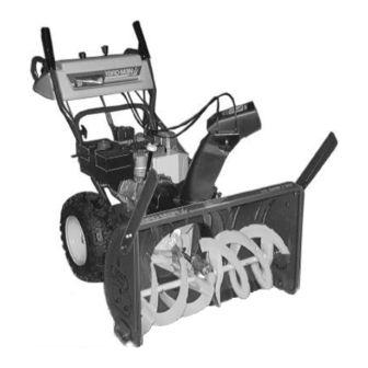
Page 8: Section 6: Controls
SECTION 6: CONTROLS Auger Drive Clutch Throttle Control Choke ignition Switch Headlight Chute Shift Tilt Lever Control Chute Crank • The snow thrower has been shown here from an upside down perspective in order to better explain the controls. Please note that the snow thrower cannot be operated in this position. -
Page 9: Section 7: Operation
SECTION 7: OPERATION GAS AND OIL FILL-UP Service the engine with gasoline and oil as instructed in the separate engine manual packed with your snow thrower. Read instructions carefully. WARNING: Never fill fuel tank indoors, with engine running or while engine is hot. Do not smoke when filling fuel tank. -
Page 10: Tire Pressure
2. To avoid possible freeze-up of starter, proceed as follows. Electric Starter: Connect power cord to switch box on engine, then to 120 volt AC receptacle. With the engine running, push starter button and spin the starter for several seconds. The unusual sound made by spinning the starter will not harm engine or starter. -
Page 11: Section 8: Adjustments
SECTION 8: ADJUSTMENTS WARNING: Never attempt to clean chute or make any adjustments while engine is running. CHUTE ASSEMBLY The distance snow is thrown can be adjusted by adjusting the angle of the chute assembly. Refer to the Control section of this manual. 1. -
Page 12: Section 9: Lubrication
SECTION 9: LUBRICATION (See Figure 13) WARNING: Disconnect the spark plug wire and ground against the engine before performing any lubrication or maintenance. WHEELS Oil or spray lubricant into wheel bearings at least once a season. Remove wheels, clean and coat axles with a multi-purpose automotive grease. -
Page 13: Section 10: Maintenance
SECTION 10: MAINTENANCE WARNING: Disconnect the spark plug wire and ground against the engine before performing any repairs or maintenance. AUGERS The augers are secured to the spiral shaft with two shear bolts and hex lock nuts. If you hit a foreign object or ice jam, the snow thrower is designed so that the bolts will shear. - Page 14 WARNING: Do not attempt to change the auger belt without the help of an assistant. It is very important that one person, standing at the operating position, firmly hold the snow thrower housing to prevent it from tipping while the other person replaces the belt.
- Page 15 Drive Belt 1. Drain the gasoline from the snow thrower, or place a piece of plastic under the gas cap. 2. Remove the plastic belt cover on the front of the engine by removing the two self-tapping screws. 3. Tip the snow thrower up and forward, so that it rests on the housing.
-
Page 16: Section 11: Off-Season Storage
the friction wheel assembly and hold assembly in position. See Figure 25. Shift Arm Sprocket Assembly Friction Wheel Figure 25 11. Slide the hex shaft through the left side of the housing and through the friction wheel assembly. 12. Insert the hex shaft through the sprocket and the spacer. -
Page 17: Section 12: Trouble Shooting Guide
SECTION 12: TROUBLE SHOOTING GUIDE Trouble Possible Cause(s) Engine fails to start Fuel tank empty, or stale fuel. Blocked fuel line. Choke not in ON position Faulty spark plug. Key not in switch on engine. Spark plug wire disconnected. Primer button not depressed. Fuel shut-off valve closed (if so equipped). -
Page 18: Section 13: Repair Parts
NOTE: For painted parts, please refer to the list of color codes below. Please add the applicable color code, wherever needed, to the part number to order a replacement part. For instance, if a part, numbered 700-xxxx, is painted yard-man green, the part number to order would be 700-xxxx-0665. - Page 19 Ref. No. Part No. Code 05931 684-0040B 684-0055A 684-0065 705-5226 710-0260 710-0451 710-0459A 710-0604 710-0703 710-0890A 712-0116 712-0324 712-0429 712-0798 712-3010 712-3068 715-0114 731-1379 732-0611 736-0119 736-0169 Ref. No. Description Bearing Housing Auger Housing Assy. 26” Auger Housing Assy. 30” Impeller Assy.
- Page 20 Please add the applicable color code, wherever needed, to the part number to order a replace- ment part. For instance, if a part, numbered 700-xxxx, is painted yard-man green, the part number to order would be 700-xxxx-0665. Yard-Man Green: 0665...
- Page 21 Ref. No. Part No. Code 618-0043 618-0044 618-0303A 656-0012A 684-0014B 684-0042B 684-0130 684-0131 710-0599 710-0788 710-1652 711-1267 711-1268 711-1364 712-0711 712-3017 713-0233 713-0374 713-0413 713-0472 714-0104 714-0474 716-0102 721-0263 732-0209 732-0264 736-0105 736-0160 Ref. No. Description Dogg Assembly: RH Dogg Assembly: LH Shift Assembly: Steerable Drive Friction Wheel Disc Assy.
- Page 22 Ref. No. Part No. 710-0262 710-0451 710-0805 710-0896 710-3015 712-0429 712-3027 731-0851A 731-1300A 731-1313B 731-1320 736-0159 736-0506 746-0896 746-0901 784-5594 784-5604 Code Description Carriage Bolt: 5/16-18 x 1.5” Carriage Bolt: 5/16-18 x 0.75” Hex Bolt: 5/16-18 x 1.5 Gr. 5 Hex Washer Head AB Screw: 1/4-14 x 0.625”...
- Page 23 Please add the appli- cable color code, wherever needed, to the part number to order a replacement part. For instance, if a part, numbered 700-xxxx, is painted yard-man green, the part number to order would be 700-xxxx-0665. Yard-Man Green: 0665 Yard-Man Yellow:)0674...
- Page 24 Please add the applicable color code, wherever needed, to the part number to order a replacement part. For instance, if a part, numbered 700-xxxx, is painted yard-man green, the part number to order would be 700-xxxx-0665. Yard-Man Green: 0665 Yard-Man Yellow:)0674...
- Page 25 Ref. No. Part No. Code 684-0008A Shift Arm Assembly 684-0053 Chute Crank Assembly 705-5266 Chute Crank Bracket 710-0262 Carr. Bolt 5/16-18 x 1.5 710-0449 Carr. Screw 5/16-18 x 2.25 Gr.5 710-0788 Hex Washer Head TT Screw 1/4-20 x 1.0 710-0890A Shear Bolt 5/16-18 x 1.5 710-3008 Hex Bolt 5/16-18 x 0.75...
- Page 26 NOTE: For painted parts, please refer to the list of color codes below. Please add the applicable color code, wherever needed, to the part number to order a replacement part. For instance, if a part, numbered 700-xxxx, is painted yard-man green, the part number to order would be 700-xxxx-0665. Yard-Man Green: 0665...
- Page 27 Optional Parts: Following optional parts are available for your snow thrower. Please call 1-800-800-7310 to order these parts. While ordering, do not forget to mention the applicable part number. Tire Chain: Part Number Wheel Size Wheel Size (with Sno Hog (without Sno Hog Tire) Tire)
- Page 28 MANUFACTURER’S LIMITED WARRANTY FOR: For TWO YEARS from the date of retail purchase within the United States of America, its possessions and territories, MTD PRODUCTS INC will, at its option, repair or replace, for the original purchaser, free of charge, any part or parts found to be defective in material or workmanship.