Yamaha RX-497 Owner's Manual
Yamaha stereo receiver owner's manual
Hide thumbs
Also See for RX-497:
- Owner's manual (326 pages) ,
- Service manual (46 pages) ,
- Owner's manual (53 pages)
Table of Contents
Advertisement
Advertisement
Table of Contents

Related Manuals for Yamaha RX-497


Summary of Contents for Yamaha RX-497
- Page 1 RX-497 Stereo Receiver OWNER’S MANUAL...
-
Page 2: Important Safety Instructions
We Want You Listening For A Lifetime YAMAHA and the Electronic Industries Association’s Consumer Electronics Group want you to get the most out of your equipment by playing it at a safe level. One that lets the sound come through loud and clear without annoying blaring or distortion –... - Page 3 This product, when installed as indicated in the instructions contained in this manual, meets FCC requirements. Modifications not expressly approved by Yamaha may void your authority, granted by the FCC, to use the product. 2 IMPORTANT: When connecting this product to accessories and/or another product use only high quality shielded cables.
- Page 4 YAMAHA will not be held responsible for any damage resulting from use of this unit with a voltage other than specified.
-
Page 5: Table Of Contents
INTRODUCTION FEATURES... 2 SUPPLIED ACCESSORIES ... 2 CONTROLS AND FUNCTIONS ... 3 Front panel ... 3 Front panel display ... 5 Rear panel ... 6 Remote control... 7 Installing batteries in the remote control ... 9 Using the remote control ... 9 PREPARATION CONNECTIONS ... -
Page 6: Features
FEATURES Built-in 2-channel power amplifier ◆ Minimum RMS output power 75 W + 75 W (8 Ω), 0.04% THD, 20 Hz to 20 kHz ◆ Highly dynamic power, low impedance drive capability Sophisticated AM/FM tuner ◆ 40-station random access preset tuning ◆... -
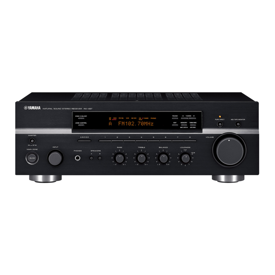
Page 7: Controls And Functions
Receives infrared signals from the remote control. Note Switch the remote control ID between ID1 and ID2 when using multiple YAMAHA receivers or amplifiers (see pages 35, 36). 6 Front panel display Shows information about the operational status of this unit. -
Page 8: Phones Jack
CONTROLS AND FUNCTIONS 7 EDIT, SEARCH MODE Exchanges the assignment of two preset stations with each other when TUNER is selected as the input source (see page 25). Switches between search modes when XM is selected as the input source (see page 29). 8 FM/AM, XM ANT (ANTENNA) Switches the reception band between AM and FM when TUNER is selected as the input source (see page 20). -
Page 9: Front Panel Display
Front panel display DTV/CBL ZONE2 ZONE3 MD/TAPE MON MEMORY AUTO TUNED STEREO SLEEP 1 SP (SPEAKERS) A/B indicators Light up according to the set of speakers selected. Both indicators light up when both sets of speakers are selected. 2 ZONE 2 indicator Lights up when Zone 2 is turned on. -
Page 10: Rear Panel
CONTROLS AND FUNCTIONS Rear panel TUNER VIDEO AUDIO DTV/ DTV/ (PLAY) 75Ω UNBAL. (REC) (PLAY) AUDIO MONITOR MD/TAPE (REC) ZONE 2 PHONO OUTPUT 1 Antenna terminals Connect FM and AM antennas. See page 12 for connections information. 2 AUDIO/VIDEO jacks Connect audio and video components. -
Page 11: Remote Control
This section describes the function of each button on the remote control used to control this unit or other components made by YAMAHA or other manufacturers. The functions of the buttons used to control your other audio and video components are the same as those of the corresponding buttons on those components. - Page 12 CONTROLS AND FUNCTIONS 9 SPEAKERS A/B Turns on or off the set of speakers connected to the SPEAKERS A and/or SPEAKERS B terminals on the rear panel of this unit when the corresponding button is pressed each time. 0 CODE SET Use to set up remote control codes (see page 41).
-
Page 13: Installing Batteries In The Remote Control
Installing batteries in the remote control ■ Notes on batteries • Change all of the batteries if the operation range of the remote control decreases. • Use AA, R6, UM-3 batteries for the remote control. • Make sure that the polarities are correct. See the illustration inside the battery compartment of each remote control. •... -
Page 14: Connections
CONNECTIONS CAUTION • Do not connect this unit or other components to the main power until all connections between components are complete. • Do not let the bare speaker wires touch each other or do not let them touch any metal part of this unit. This could damage this unit and/ or the speakers. -
Page 15: Connecting Speakers
Connecting speakers Remove approximately 10 mm (3/8 in) of insulation from the end of each speaker cable and twist the exposed wires of the cable together to prevent short circuits. 10 mm (3/8 in) Unscrew the knob. Red: positive (+) Black: negative (–) Insert one bare wire into the hole in the side of each terminal. -
Page 16: Connecting The Am And Fm Antennas
• A properly installed outdoor antenna provides clearer reception than an indoor one. If you experience poor reception quality, an outdoor antenna may improve the quality. Consult your nearest authorized YAMAHA dealer or service center about outdoor antennas. • If you connect an outdoor FM antenna to this unit, do not connect the indoor FM antenna to this unit. -
Page 17: Connecting The Am Loop Antenna
5 to 10 m of vinyl-covered wire to the AM ANT terminal and extend it outdoors from a window. Consult your nearest authorized YAMAHA dealer or service center about outdoor antennas. • The AM loop antenna should always be connected, even if an outdoor AM antenna is connected to this unit. -
Page 18: Connecting The Power Supply Cord
CONNECTIONS Connecting the power supply cord Plug the power supply cord into the AC wall outlet after all other connections are complete. VOLTAGE SELECTOR SPEAKERS CLASS 2 WIRING IMPEDANCE SELECTOR SET BEFORE POWER ON A OR B: 4ΩMIN. /SPEAKER A + B: 8ΩMIN. /SPEAKER A OR B: 8ΩMIN. -
Page 19: Playing And Recording
PLAYING AND RECORDING CAUTION Extreme caution should be exercised when you play back CDs encoded in DTS. If you play back a CD encoded in DTS on a DTS-incompatible CD player, you will only hear some unwanted noise that may damage your speakers. -
Page 20: Adjusting The Tonal Quality
PLAYING AND RECORDING Adjusting the tonal quality ■ Adjusting the BALANCE control Adjusts the sound output balance of the left and right speakers to compensate for sound imbalance caused by speaker locations or listening room conditions. BALANCE ■ Using the PURE DIRECT button Routes input signals from your audio sources so that the input signals bypass the BASS, TREBLE, BALANCE and LOUDNESS controls, thus eliminating any alterations to... -
Page 21: Recording A Source
Recording a source Notes • The VOLUME, BASS, TREBLE, BALANCE and LOUDNESS controls and the PURE DIRECT buttons have no effect on the source being recorded. • Check the copyright laws in your country to record from records, CDs, radio, etc. Recording copyright-protected material may infringe on copyright laws. -
Page 22: Using The Sleep Timer
PLAYING AND RECORDING Using the sleep timer Use this feature to automatically set this unit to the standby mode after a certain amount of time. The sleep timer is useful when you are going to sleep while this unit is playing or recording a source. The sleep timer also automatically turns off any external components connected to the AC OUTLETS. -
Page 23: Muting The Sound Output
Muting the sound output Press MUTE on the remote control to mute the sound output. The MUTE indicator flashes in the front panel display. MUTE After a few seconds, MUTE ON disappears from the front panel display. Press MUTE on the remote control again to resume the sound output. -
Page 24: Fm/Am Tuning
FM/AM TUNING There are 2 tuning methods; automatic and manual. Select either method according to your preference and the strength of station signals. Automatic tuning Automatic tuning is effective when station signals are strong and there is no interference. ZONE 2 ON/OFF ZONE CONTROL MASTER A/B/C/D/E... -
Page 25: Manual Tuning
Manual tuning Manual tuning is effective when station signals are weak. 2 4 3 ZONE 2 ON/OFF FM/AM XM/ANT ZONE CONTROL EDIT SEARCH MODE MASTER A/B/C/D/E CATEGORY INPUT BASS TREBLE BALANCE MAIN ZONE SPEAKERS ON/OFF – – Rotate the INPUT selector (or press TUNER on the remote control) to select TUNER as the input source. -
Page 26: Automatic Preset Tuning
FM/AM TUNING Automatic preset tuning You can use the automatic preset tuning method to automatically store FM stations. This function enables this unit to automatically tune into FM stations with strong signals and store up to 40 (8 stations in each of the 5 groups, A1 to E8) of those received stations in order. - Page 27 ■ Customized automatic preset tuning You can specify a preset station group and a preset station number from which this unit stores the FM stations received by automatic preset tuning. Press and hold MEMORY on the front panel for more than 3 seconds. MEMORY MAN'L/AUTO FM Press A/B/C/D/E and then press one of the...
-
Page 28: Manual Preset Tuning
FM/AM TUNING Manual preset tuning You can also manually store up to 40 stations (8 stations in each of the 5 groups, A1 to E8). You can then easily recall any preset stations by selecting the preset station numbers where they are stored. ZONE 2 ON/OFF ZONE CONTROL MASTER... -
Page 29: Selecting Preset Stations
Selecting preset stations You can tune into the desired station simply by selecting the preset station number where it is stored. ZONE 2 ON/OFF FM/AM XM/ANT ZONE CONTROL EDIT SEARCH MODE MASTER A/B/C/D/E CATEGORY INPUT BASS TREBLE BALANCE MAIN ZONE PHONES SPEAKERS ON/OFF... -
Page 30: Xm Satellite Radio Tuning
XM SATELLITE RADIO TUNING XM SATELLITE RADIO TUNING What is XM Satellite Radio? XM Satellite Radio is the satellite radio service with millions of listeners across the United States broadcasting live daily. The XM Satellite Radio channel lineup includes more than 150 digital channels of choice from coast to coast: 67 commercial-free music channels, featuring hip hop to opera, classical to country, bluegrass to blues;... -
Page 31: Xm Satellite Radio Functions
XM Satellite Radio functions This section describes the functions of each control used for the XM Satellite Radio tuning. Note The following controls on the front panel and the remote control are only available when is selected as the input source and the XM Connect-and-Play digital antenna accessory is connected to the jack on the rear panel of this unit (see “XM Satellite... - Page 32 Selects the Preset Search mode. C CD/XM switch Switches the function of the control buttons on the Zone 2 remote control numbered 2, 7, 9, 0, A and B between controlling YAMAHA CD players and controlling the XM Satellite Radio features.
-
Page 33: Activating Xm Satellite Radio
Activating XM Satellite Radio To sign up for an account with the XM Satellite Radio service, an XM Satellite Radio ID number is required. Follow the procedure below to check your ID number, and then visit the website at “http://activate.xmradio.com” or call “1-800-XM-RADIO (1-800-967-2346)”... -
Page 34: Basic Xm Satellite Radio Operations
XM SATELLITE RADIO TUNING Basic XM Satellite Radio operations ZONE 2 ON/OFF ZONE CONTROL MASTER A/B/C/D/E CATEGORY INPUT BASS TREBLE BALANCE MAIN ZONE PHONES SPEAKERS ON/OFF – – Rotate the INPUT selector on the front panel (or press XM on the remote control) to select XM as the input source. -
Page 35: Xm Satellite Radio Search Modes
XM Satellite Radio search modes You can search for the desired channel by using one of the three search modes (All Channel Search mode, Category Search mode or Preset Search mode). You can also enter the number directly to select the desired channel (For details, see “Direct Number Access mode”... - Page 36 XM SATELLITE RADIO TUNING ■ Category Search mode ZONE 2 ON/OFF ZONE CONTROL MASTER A/B/C/D/E CATEGORY INPUT BASS TREBLE BALANCE MAIN ZONE PHONES SPEAKERS ON/OFF – – Repeat step 1 in “Basic XM Satellite Radio operations”. Press SEARCH MODE on the front panel (or SRCH MODE on the remote control) repeatedly to select the Category Search mode.
-
Page 37: Setting Xm Satellite Radio Preset Channels
■ Direct Number Access mode ZONE 2 ON/OFF FM/AM XM/ANT ZONE CONTROL EDIT SEARCH MODE MASTER A/B/C/D/E CATEGORY INPUT BASS TREBLE BALANCE MAIN ZONE PHONES SPEAKERS ON/OFF – – Repeat step 1 in “Basic XM Satellite Radio operations”. Press SEARCH MODE on the front panel (or SRCH MODE on the remote control) repeatedly to select the All Channel Search mode or the Category Search mode. - Page 38 XM SATELLITE RADIO TUNING Press CATEGORY on the front panel (or A-E/ CAT. j / i on the remote control) to select the preset channel group (A to E). The preset channel group letter appears. A/B/C/D/E CATEGORY A-E/CAT. Front panel Press one of the preset station/channel number buttons on the front panel (or PRESET/CH u / d on the remote control) to...
-
Page 39: Advanced Setup
■ ADVANCED SETUP menu parameters Change the initial settings (indicated in bold under each parameter) to reflect the needs of your listening environment. Factory presets PRESET Use to reset all parameters to the factory presets. Choices: CANCEL, RESET • Select CANCEL if you do not want the parameters of this unit to be initialized when you reset the factory presets. -
Page 40: Switching The Remote Control Id
When you change the remote control ID, you must switch the remote control ID of this unit (see page 35). When using multiple YAMAHA receivers or amplifiers with the same default code setting, you may unwantedly operate those components simultaneously. -
Page 41: Zone 2
• An amplifier and speakers for the second room Some YAMAHA models are able to connect directly to the REMOTE OUT jack on the rear panel of this unit. If you own these products, you may not need to use an infrared emitter. Up to six YAMAHA components can be connected as shown below. -
Page 42: Controlling Zone 2
ZONE 2 Controlling Zone 2 You can control the input source of Zone 2 independently of the listening conditions in the main room. Press ZONE 2 ON/OFF on the front panel to turn on Zone 2. ZONE 2 ON/OFF Press ZONE 2 CONTROL on the front panel The ZONE 2 indicator flashes in the front panel display. -
Page 43: Remote Control Features
REMOTE CONTROL FEATURES ■ Controlling other components The shaded areas below can be used to control other audio and video components made by YAMAHA and other manufacturers. Each button has a different function depending on the selected component. Select the component you want to control by pressing one of the input selector buttons. -
Page 44: Controlling Other Components
REMOTE CONTROL FEATURES Controlling other components In addition to controlling this unit, you can also control other audio and video components made by YAMAHA and other manufacturers using the supplied remote control. To control other components, you must set the appropriate remote control codes. -
Page 45: Setting Remote Control Codes
CBL button. However, other remote control codes can be set for any input selector buttons except DTV/CBL. Note You may not be able to operate your other YAMAHA components even if the YAMAHA remote control code is initially set as listed above. In this case, try setting other YAMAHA remote control codes. -
Page 46: Troubleshooting
Refer to the chart below if this unit does not function properly. If the problem you are experiencing is not listed below or if the instructions below do not help, set this unit to the standby mode, disconnect the power cord, and contact the nearest authorized YAMAHA dealer or service center. ■ General... - Page 47 The power of this unit is turned off, or this The sound is unit is set to the standby mode. degraded when listening with the headphones connected to the CD player or the tape deck connected to this unit. The LOUDNESS control is functioning. The sound level is low.
-
Page 48: Xm Satellite Radio
TROUBLESHOOTING ■ XM Satellite Radio Error message CHECK ANTENNA The XM Connect-and-Play digital antenna accessory is not connected, or does not work properly. UPDATING The XM user encryption code is being updated. NO SIGNAL The signal is too weak. LOADING It takes longer than four seconds for audio or text data to be decoded. -
Page 49: Specifications
AUDIO SECTION • Minimum RMS Output Power (8 Ω , 20 Hz to 20 kHz, 0.04% THD) ... 75 W + 75 W • Dynamic Power (IHF) (8/6/4/2 Ω) ... 105/125/150/178 W • Maximum Output Power [Europe model only] (1 kHz, 0.7% THD, 4 Ω) ... 105 W •... -
Page 50: Dvd Player
Ferguson 223, 265, 266 Thomson First line Toshiba Funai 277, 278 Videch Fisher 295, 233 Wards Fraba Yamaha 293, 297, 234, 235, 236 LG/Goldstar 297, 298, 239, 237 Goodmans 296, 298, 223 Admiral Grundig 229, 238, 249 Aiwa Hitachi 297, 239, 242,... - Page 51 YAMAHA ELECTRONICS (UK) LTD. YAMAHA HOUSE, 200 RICKMANSWORTH ROAD WATFORD, HERTS WD18 7GQ, ENGLAND YAMAHA SCANDINAVIA A.B. J A WETTERGRENS GATA 1, BOX 30053, 400 43 VÄSTRA FRÖLUNDA, SWEDEN YAMAHA MUSIC AUSTRALIA PTY, LTD. 17-33 MARKET ST., SOUTH MELBOURNE, 3205 VIC., AUSTRALIA...
- Page 52 If the plug should still fail to fit, contact your electrician to replace your obsolete outlet. Do not defeat the safety purpose of the polarized plug. RX-497/RX-397 13 Power-Cord Protection – Power-supply cords should be routed so that they are not likely to be walked on or pinched...
- Page 53 20 Replacement Parts – When replacement parts are required, be sure the service technician has used replacement parts specified by the manufacturer or have the same characteristics as the original part. Unauthorized substitutions may result in fire, electric shock, or other hazards.