Table of Contents
Advertisement
80W + 80W (8Ω) RMS Output Power, 0.019% THD, 20-20,000 Hz
CD DIRECT AMP Switch to Reproduce the Purest CD Sound
PURE DIRECT Switch to Reproduce the Purest Source Sound
Thank you for selecting this YAMAHA stereo receiver.
OWNER'S MANUAL
CONTENTS
Safety Instructions ................... 2
Supplied Accessories .............. 3
Connections ............................. 4
Basic Operations ...................... 7
Tuning Operations .................. 10
Preset Tuning ......................... 11
Remote Control Transmitter ... 13
Troubleshooting ...................... 15
Specifications ......................... 16
High Dynamic Power, Low Impedance Drive Capability
Continuously Variable Loudness Control
40-Station Random Access Preset Tuning
Preset Station Shifting Capability (Preset Editing)
IF Count Direct PLL Synthesizer Tuning System
IMPORTANT!
Please record the serial number of this
unit in the space below.
Serial No.:
The serial number is located on the rear
of the unit.
Retain this Owner's Manual in a safe
place for future reference.
WARNING
TO REDUCE THE RISK OF FIRE OR
ELECTRIC SHOCK, DO NOT EXPOSE
THIS UNIT TO RAIN OR MOISTURE.
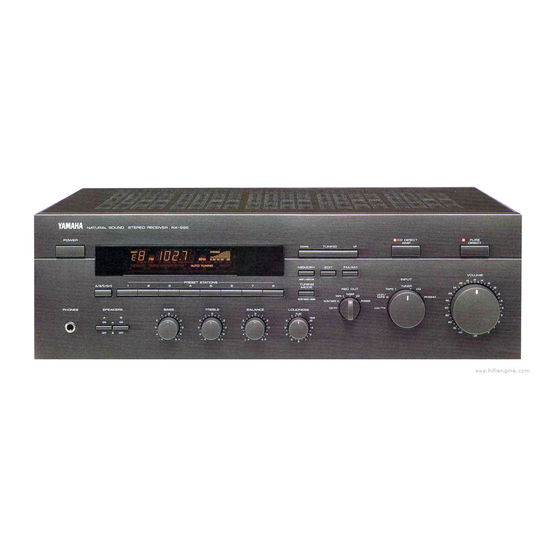
RX-595
Natural Sound Stereo Receiver
Automatic Preset Tuning
Video Signal Input/Output Capability
Remote Control Capability
• Explanation of Graphical Symbols
CAUTION
RISK OF ELECTRIC
SHOCK
CAUTION: TO REDUCE THE RISK OF
ELECTRIC SHOCK, DO NOT REMOVE
COVER (OR BACK), NO USER-SERVICEABLE
PARTS INSIDE, REFER SERVICING TO
QUALIFIED SERVICE PERSONNEL.
The lightning flash with arrowhead
symbol, within an equilateral triangle,
is intended to alert you to the
presence of uninsulated "dangerous
voltage" within the product's
enclosure that may be of sufficient
magnitude to constitute a risk of
electric shock to persons.
The exclamation point within an
equilateral triangle is intended to alert
you to the presence of important
operating and maintenance
(servicing) instructions in the
literature accompanying the
appliance.
Advertisement
Table of Contents

Related Manuals for Yamaha RX-595


Summary of Contents for Yamaha RX-595
-
Page 1: Table Of Contents
High Dynamic Power, Low Impedance Drive Capability CD DIRECT AMP Switch to Reproduce the Purest CD Sound PURE DIRECT Switch to Reproduce the Purest Source Sound Thank you for selecting this YAMAHA stereo receiver. OWNER’S MANUAL CONTENTS Safety Instructions ... 2 Supplied Accessories ... -
Page 2: Safety Instructions
Since hearing damage from loud sounds is often undetectable until it is too late, YAMAHA and the Electronic Industries Association’s Consumer Electronics Group recommend you to avoid prolonged exposure from excessive volume levels. -
Page 3: Supplied Accessories
This product, when installed as indicated in the instructions contained in this manual, meets FCC requirements. Modifications not expressly approved by Yamaha may void your authority, granted by the FCC, to use the product. 2. IMPORTANT : When connecting this product to accessories and/or another product use only high quality shielded cables. -
Page 4: Connections
Before attempting to make any connections to or from this unit, be sure to first switch OFF the power to this unit and to any other components to which connections are being made. CONNECTIONS WITH OTHER COMPONENTS When making connections between this unit and other components, be sure all connections are made correctly, that is to say L (left) to L, R (right) to R, “+”... -
Page 5: Connecting Speakers
Connect the REMOTE CONTROL IN terminal to the EMITTER terminal (FROM INDEPENDENT ZONE, FROM ALL ZONE or FROM SELECTED ZONE) of the YAMAHA Master Zone Controller MCX-10. By connecting the REMOTE CONTROL OUT terminal to the REMOTE CONTROL IN terminal of the other component, you can also operate it with the system remote control. -
Page 6: Antenna Connections
ANTENNA CONNECTIONS Each antenna should be connected to the designated terminals correctly, referring to the following diagram. Both AM and FM indoor antennas are included with this unit. In general, these antennas will probably provide sufficient signal strength. Nevertheless, a properly installed outdoor antenna will give clearer reception than an indoor one. If you experience poor reception quality, an outdoor antenna may result in improvement. -
Page 7: Basic Operations
TO PLAY A SOURCE VOLUME –dB ∞ Set to the “ ” position. Turn the power on. POWER Select a desired input source. (For video sources, turn the TV/monitor ON.) INPUT TUNER TAPE 1 VCR/ TAPE 2 LD/TV * The name of the selected input source position will appear in the display. - Page 8 TO RECORD A SOURCE TO TAPE (OR DUB FROM A TAPE TO ANOTHER) Select the source to be recorded. REC OUT TUNER TAPE 1 VCR/TAPE 2 LD/TV Play the source. Confirm the source by selecting it with the INPUT selector and turning up the VOLUME control. INPUT TUNER TAPE 1...
-
Page 9: Selecting The Speaker System
Adjusting the BALANCE control Adjust the balance of the output volume to the left and right speakers to compensate for sound imbalance caused from speaker location or listening room conditions. BALANCE Adjusting the BASS and TREBLE controls BASS BASS : Turn this clockwise to increase (or counter- clockwise to decrease) the low frequency response. -
Page 10: Tuning Operations
Normally, if station signals are strong and there is no interference, quick automatic-search tuning (AUTOMATIC TUNING) is possible. However, if signals of the station you want to select are weak, you must tune to it manually (MANUAL TUNING). AUTOMATIC TUNING Select the reception band (FM or AM) while watching the display. -
Page 11: Preset Tuning
MANUAL PRESET TUNING This unit can store station frequencies (selected by tuning operation) by using the preset station buttons. With this function, you can select any desired station by only pressing the corresponding preset station button. Up to 40 stations (8 stations x 5 pages) can be stored. - Page 12 AUTOMATIC PRESET TUNING You can also make use of an automatic preset tuning function for FM stations only. By this function, this unit performs automatic tuning and stores FM stations with strong signals sequentially. Up to 40 stations are stored automatically in the same way as in the manual preset tuning method on page 11.
-
Page 13: Remote Control Transmitter
EXCHANGING PRESET STATIONS You can exchange the places of two preset stations with each other as shown below. Example) If you want to shift the preset station on E1 to A5, and vice versa. Recall the preset station on E1 (by following the method of “To recall a preset station”... - Page 14 The remote control transmitter provided with this unit is designed to control all the most commonly used functions of the unit. If the CD player and tape deck connected to this unit are YAMAHA components designed for remote control compatibility, then this remote control transmitter will also control various functions of each component.
-
Page 15: Troubleshooting
If the unit fails to operate normally, check the following points to determine whether the fault can be corrected by the simple measures suggested. If it cannot be corrected, or if the fault is not listed in the SYMPTOM column, disconnect the power cord and contact your authorized YAMAHA dealer or service center for help. SYMPTOM The unit fails to turn on when the POWER switch is pressed. -
Page 16: Specifications
YAMAHA ELECTRONICS (UK) LTD. YAMAHA HOUSE, 200 RICKMANSWORTH ROAD WATFORD, HERTS WD1 7JS, ENGLAND YAMAHA SCANDINAVIA A.B. J A WETTERGRENS GATA 1, BOX 30053, 400 43 VÄSTRA FRÖLUNDA, SWEDEN YAMAHA MUSIC AUSTRALIA PTY, LTD. 17-33 MARKET ST., SOUTH MELBOURNE, 3205 VIC., AUSTRALIA Channel Separation (Vol.