Table of Contents
Advertisement
Quick Links
Owner's Manual
Thank you for choosing the Yamaha AD8HR AD converter with remote microphone
preamp.
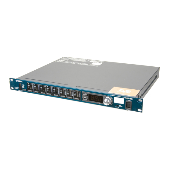
The AD8HR is an eight-channel AD converter equipped with remote microphone
preamps that feature 96kHz, 24-bit linear AD conversion, 128-times oversampling,
and a dynamic range of 110dB. Its input section features balanced XLR connectors,
high-quality mic preamps, +48V phantom power, and support for both mic and line-
level inputs. The output section supports the AES/EBU format and features a high
sampling frequency of 88.2/96kHz. You can easily adjust the gain for each channel
(in 1dB steps) and set up the high pass filter from the front panel. These settings are
stored in the unit's backup memory, and are retained even after the power is turned
off. In addition, a special protocol enables you to remotely control the unit from a
connected computer or other device.
Please read this manual thoroughly before using the unit to take the greatest
advantage of the AD8HR's extensive features for the longest period of time. After you
read this manual, please keep it in a safe place.
E
Advertisement
Table of Contents

Related Manuals for Yamaha AD8HR AD


Summary of Contents for Yamaha AD8HR AD
- Page 1 Owner’s Manual Thank you for choosing the Yamaha AD8HR AD converter with remote microphone preamp. The AD8HR is an eight-channel AD converter equipped with remote microphone preamps that feature 96kHz, 24-bit linear AD conversion, 128-times oversampling, and a dynamic range of 110dB. Its input section features balanced XLR connectors, high-quality mic preamps, +48V phantom power, and support for both mic and line- level inputs.
- Page 2 WORD CLOCK AD8HR 96kHz 88.2kHz 48kHz 44.1kHz WORD CLOCK U.R.G., Pro Audio & Digital Musical Instrument Division, Yamaha Corporation /min or higher and a O or higher. O oder mehr O ou plus. /min o superior con una O o superior.
- Page 3 XLR-type connectors are wired as follows (IEC60268 standard): pin 1: ground, pin 2: hot (+), and pin 3: cold (-). Yamaha cannot be held responsible for damage caused by improper use or modifications to the device, or data that is lost or destroyed.
-
Page 4: Important Safety Instructions
Compliance with FCC regulations does * This applies only to products distributed by YAMAHA CORPORATION OF AMERICA. Explanation of Graphical Symbols The lightning flash with arrowhead symbol within an equilateral triangle is intended to alert the user to the presence of uninsulated “danger-... -
Page 5: Table Of Contents
The wire which is coloured BROWN must be connected to the termi- nal which is marked with the letter L or coloured RED. • This applies only to products distributed by Yamaha-Kemble Music (U.K.) Ltd. Table of Contents Part Names and Functions ... 5 Front Panel ... -
Page 6: Part Names And Functions
Part Names and Functions Front Panel 96kHz 88.2kHz 48kHz 44.1kHz WORD CLOCK WORD CLOCK indicators These indicators indicate the currently selected wordclock source. If the unit is not locking to the selected wordclock source, the corresponding wordclock source indicator flashes. [WORD CLOCK] button This button enables you to select the wordclock source from 44.1kHz, 48kHz, 88.2kHz, 96kHz, WORD... -
Page 7: Rear Panel
DM2000 to control the AD8HR remotely. In a multiple AD8HR system, connect an AD8HR to [HA REMOTE] connector 1 on an additional AD8HR. NOTE: Please visit the following Yamaha website for the latest information about the devices that can control the AD8HR remotely. http://www.yamahaproaudio.com/... -
Page 8: Basic Operations
Basic Operations Selecting the Wordclock You can select from the following wordclock source options: internal clock (44.1kHz, 48kHz, 88.2kHz, and 96kHz), WORD CLOCK IN, or DIGITAL OUT A. Press the [WORD CLOCK] button repeatedly to select the wordclock source. The indicator of the selected wordclock flashes rapidly. While the indicator is flashing rapidly, press the [WORD CLOCK] button again. -
Page 9: Setting The High Pass Filter
Basic Operations Setting the High Pass Filter Each channel features a high pass filter (12dB/octave) that you can turn on or off. You can set individual cut- off frequencies for each channel’s high pass filter. Press the Channel Select button to select a channel. -
Page 10: Adjusting The Led Brightness
Remote Control A special protocol enables you to control the AD8HR from a computer or Yamaha PM5D or DM2000 that is connected to [HA REMOTE] connector 1. You can also remotely control up to 255 AD8HRs that are connected to one another. -
Page 11: Connection Examples
Use a D-sub 25-pin AES/EBU cable to connect a digital audio device that supports the AES/EBU format. To connect a Yamaha PM5D or DM2000 to the AD8HR, first you must install an optional I/O card (MY8-AE, MY8-AE96S, MY8-AE96, or MY16-AE) in the PM5D or DM2000. -
Page 12: Wordclocks
Wordclocks For proper AD conversion and digital audio data transmission and reception, the D8HRs and external digital audio devices must lock to an identical wordclock. The AD8HR is capable of transmitting a wordclock signal of 44.1kHz, 48kHz, 88.2kHz, and 96kHz, you can use the AD8HR as the wordclock master and the external devices as wordclock slaves. -
Page 13: Appendix
Appendix Appendix General Specifications ■ Analog Input INPUT 1–8 XLR-3-31 Balanced AD converter 24-bit linear 128-times Oversampling ■ Digital Output DIGITAL OUT A, B D-Sub 25-pin Balanced ■ Connectors WORD CLOCK IN (75Ω Auto Terminated): BNC WORD CLOCK OUT: HA REMOTE (PC-RS422): D-Sub 9-pin with PC-RS422 switch HA REMOTE (RS422):... -
Page 14: Electrical Characteristics
Electrical Characteristics Measured at DIGITAL OUT. Output impedance of signal generator: 150Ω. ■ Frequency Response fs=44.1kHz or 48kHz @20Hz–20kHz, with reference to –1dBFs @1kHz Input Output INPUT 1–8 DIGITAL OUT 1–8 GAIN: –62 dB INPUT 1–8 DIGITAL OUT 1–8 GAIN: +10 dB fs=88.2kHz or 96kHz@20Hz-40kHz, with reference to –1dBFs @1kHz Input Output... -
Page 15: Error Messages
The AD8HR automatically diagnoses itself at the time of power up. If it detects a system abnormality, one of the following error messages appears. If an abnormality is detected, consult your Yamaha dealer. The backup battery voltage is low. If the voltage is lowered further, the stored data will be erased. Ask your dealer to replace the battery. -
Page 16: Ha Remote Pin Assignment Table
Attach the rubber feet in the positions marked by small circles on the bottom. Specifications and descriptions in this owner’s manual are for information purposes only. Yamaha Corp. reserves the right to change or modify products or specifications at any time without prior notice. - Page 17 For details of products, please contact your nearest Yamaha representative or the authorized distributor listed below. Pour plus de détails sur les produits, veuillez-vous adresser à Yamaha ou au distributeur le plus proche de vous figurant dans la liste suivante.