Table of Contents
Advertisement
Advertisement
Table of Contents

Related Manuals for Yamaha RX-V740


Summary of Contents for Yamaha RX-V740
- Page 1 RX-V740 AV Receiver OWNER’S MANUAL...
-
Page 2: Important Safety Instructions
IMPORTANT SAFETY INSTRUCTIONS CAUTION RISK OF ELECTRIC SHOCK DO NOT OPEN CAUTION: TO REDUCE THE RISK OF ELECTRIC SHOCK, DO NOT REMOVE COVER (OR BACK). NO USER-SERVICEABLE PARTS INSIDE. REFER SERVICING TO QUALIFIED SERVICE PERSONNEL. • Explanation of Graphical Symbols The lightning flash with arrowhead symbol, within an equilateral triangle, is intended to alert you to the presence of uninsulated “dangerous... - Page 3 This product, when installed as indicated in the instructions contained in this manual, meets FCC requirements. Modifications not expressly approved by Yamaha may void your authority, granted by the FCC, to use the product. IMPORTANT : When connecting this product to accessories and/or another product use only high quality shielded cables.
- Page 4 This Class B digital apparatus complies with Canadian ICES-003. Since hearing damage from loud sounds is often undetectable until it is too late, YAMAHA and the Electronic Industries Association’s Consumer Electronics Group recommend you to avoid prolonged exposure from excessive volume levels.
-
Page 5: Table Of Contents
INTRODUCTION CONTENTS ... 1 FEATURES ... 2 GETTING STARTED ... 3 Supplied accessories ... 3 Installing batteries in the remote control ... 3 CONTROLS AND FUNCTIONS ... 4 Front panel ... 4 Remote control ... 6 Front panel display ... 8 PREPARATION CONNECTIONS ... -
Page 6: Features
N Dolby Pro Logic/Dolby Pro Logic II decoder N Dolby Digital/Dolby Digital EX decoder N DTS/DTS-ES Matrix 6.1, Discrete 6.1, DTS Neo:6 Decoder N CINEMA DSP: Combination of YAMAHA DSP technology and Dolby Pro Logic, Dolby Digital or N Virtual CINEMA DSP N SILENT CINEMA DSP... -
Page 7: Getting Started
Supplied accessories After unpacking, check that the following parts are contained. Remote control TRANSMIT RE-NAME CLEAR CODE SET SYSTEM POWER STANDBY SLEEP 6CH INPUT PHONO V-AUX TUNER MD/CD-R D-TV/CBL VCR 1 VCR2/DVR SELECT POWER POWER AUDIO DISC SKIP LEVEL SET MENU MUTE TITLE MENU... -
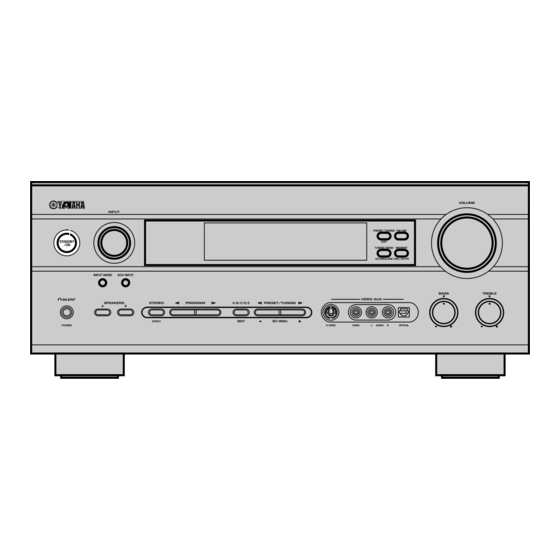
Page 8: Controls And Functions
CONTROLS AND FUNCTIONS Front panel INPUT RDS MODE/FREQ STANDBY PTY SEEK MODE START INPUT MODE 6CH INPUT SILENT SPEAKERS STEREO EFFECT PHONES RDS MODE/FREQ PTY SEEK MODE (U.K. and Europe models only) 1 STANDBY/ON Turns the unit on, or sets it in standby mode. When you turn the unit on, you will hear a click and there will be a 4 to 5-second delay before it can reproduce sound. - Page 9 SILENT (PHONES jack) Allows you to enjoy DSP effects when listening with headphones. When you connect headphones to the headphone jack, no signals are output to the speakers or the OUTPUT jacks. e SPEAKERS A/B Turns the set of main speakers connected to the A and/or B terminals on or off.
-
Page 10: Remote Control
CONTROLS AND FUNCTIONS Remote control This section describes the controls and functions of the remote control. Make sure that the AMP mode is selected before use. RE - NAME TRANSMIT CLEAR CODE SET SYSTEM POWER STANDBY SLEEP V - AUX TUNER MD/CD-R D - TV/CBL... -
Page 11: Using The Remote Control
u SELECT k/n Set the remote to control a component other than the one selected with the input selector buttons. i AMP Switches the function of the same controls between AMP and the component selected using the input selector buttons. o VOL +/–... -
Page 12: Front Panel Display
CONTROLS AND FUNCTIONS Front panel display VCR2/DVR VCR1 VIRTUAL NIGHT MATRIX DISCRETE HiFi SILENT DIGITAL ~~~~~~~~~~~~~~ ZONE2 (U.S.A., Canada and Australia models only) 1 Processor indicators The indicators for the various decoders light up when the decoders are in use. 2 VIRTUAL indicator Lights up when using Virtual CINEMA DSP. -
Page 13: Connections
Before connecting components CAUTION Do not connect this unit or other components to the mains power until all connections between the components have been completed. • Be sure all connections are made correctly, that is to say L (left) to L, R (right) to R, “+” to “+” and “–” to “–”. -
Page 14: Connecting Video Components
CONNECTIONS Connecting video components Refer to the connection examples on the next page. I Types of video jacks COMPONENT VIDEO VIDEO S VIDEO 1 VIDEO jack Conventional composite video signal. 2 S VIDEO jack Transmits color and luminance separately and achieves high-quality color reproduction. - Page 15 DVD player OPTICAL OUTPUT AUDIO OUTPUT SIGNAL AUDIO AUDIO VIDEO VIDEO S VIDEO PHONO DIGITAL INPUT D-TV /CBL COAXIAL OPTICAL D-TV/CBL (PLAY) VCR-1 /CD-R (REC) MD/CD-R MAIN VCR 2 /DVR SURROUND MD/CD-R MONITOR OUT OPTICAL VIDEO S VIDEO DIGITAL WOOFER CENTER OUTPUT 6CH INPUT...
-
Page 16: Connecting Audio Components
CONNECTIONS Connecting audio components I Connecting a CD player Connect the coaxial digital output jack on your CD player to the DIGITAL INPUT CD jack on this unit. • Use the AUDIO jacks on this unit for a CD player which does not have coaxial digital output jack. -
Page 17: Connecting The Antennas
(inch) reception than an indoor one. If you experience poor reception quality, an outdoor antenna may improve the quality. Consult the nearest authorized YAMAHA dealer or service center about the outdoor antennas. FREQUENCY STEP switch (China and General models only) -
Page 18: Connecting An External Amplifier
Rear center channel line output jack. 5 SUBWOOFER jack When using a subwoofer with built-in amplifier, including the YAMAHA Active Servo Processing Subwoofer System, connect the input jack of the subwoofer system to this jack. Low bass signals distributed from the main, center and/or rear channels are directed to this jack in accordance with your SPEAKER SET selections. -
Page 19: Connecting The Speakers
LFE (low-frequency effect) channel with high fidelity when playing back Dolby Digital or DTS signals. The YAMAHA Active Servo Processing Subwoofer System is ideal for natural and lively bass reproduction. I Speaker placement Refer to the following diagram when you place the speakers. -
Page 20: Impedance Selector Switch
CONNECTIONS I Connections Be sure to connect the left channel (L), right channel (R), “+” (red) and “–” (black) in accordance with the markers on this unit, the speakers, and the speaker cables. If the connections are faulty, no sound will be heard from the speakers, and if the polarity of the speaker connections is incorrect, the sound will be unnatural and lack bass. -
Page 21: Subwoofer Jack
A rear center speaker can be connected to these terminals. SUBWOOFER jack When using a subwoofer with built-in amplifier, including the YAMAHA Active Servo Processing Subwoofer System, connect the input jack of the subwoofer system to this jack. This unit will direct low bass signals distributed from the main, center and/or rear channels to this jack in accordance with your SPEAKER SET selections. -
Page 22: Connecting The Power Supply Cords
CONNECTIONS Connecting the power supply cords VOLTAGE SELECTOR VOLTAGE SELECTOR AC OUTLETS SWITCHED IMPEDANCE SELECTOR SET BEFORE POWER ON MAIN A OR B : 4ΩMIN. /SPEAKER MAIN A OR B : 8ΩMIN. /SPEAKER A+B : 8ΩMIN. /SPEAKER A+B : 16ΩMIN. /SPEAKER CENTER 6ΩMIN. -
Page 23: On-Screen Display (Osd)
ON-SCREEN DISPLAY (OSD) You can display operational information for this unit on a video monitor. It is much easier to see the available options and parameters on a monitor than by reading this information on the front panel display. • If a video source is playing, the OSD is superimposed over the video image. -
Page 24: Basic System Settings
The “BASIC” menu allows you to set some of the basic “SOUND” menu parameters with a minimum of effort. If you wish to configure the unit more precisely to suit your listening environment, use the more detailed parameters from the “SOUND”... -
Page 25: Set Menu
SET MENU BASIC SOUND 1 SETUP Press j / i to alter the settings for each parameter. Use d to move to the next setting. 1 ROOM Choose from S/M/L. 2 SUBWOOFER Choose either of YES/NONE. 3 SPEAKERS Choose from 2/3/4/5/6 spk. 4 SET/CANCEL CANCEL Choose either of SET/CANCEL. -
Page 26: Setting The Unit To Match Your Speaker System
BASIC SYSTEM SETTINGS Setting the unit to match your speaker system Follow the instructions below to set the amplifier output to match the size of your room and speakers. Press u / d to cycle through parameters 1 through 4, and j / i to alter the parameter setting. -
Page 27: Playback
INPUT STANDBY INPUT MODE 6CH INPUT SILENT SPEAKERS STEREO PROGRAM A/B/C/D/E PRESET/TUNING EFFECT NEXT SET MENU PHONES S VIDEO VIDEO TRANSMIT RE-NAME CLEAR CODE SET SYSTEM POWER STANDBY SLEEP 6CH INPUT PHONO DISC SKIP V-AUX TUNER MD/CD-R D-TV/CBL VCR 1 VCR2/DVR LEVEL TITLE... - Page 28 PLAYBACK Start playback or select a broadcast station on the source component. Refer to the operation instructions for the component. Adjust the volume to the desired level. The volume level is displayed digitally. Example: –70 dB Control range: VOLUME MUTE (minimum) to 0 dB (maximum) The volume level indicator also shows the current volume level as a bar graph.
-
Page 29: Input Modes And Indications
Input modes and indications This unit is equipped with a variety of input jacks. You can select the type of input signals you wish to use. Each time you turn on the unit power, the input mode is set to the “INPUT 2 INPUT MODE” setting defined in the set menu. -
Page 30: Selecting A Sound Field Program
PLAYBACK Selecting a sound field program You can enhance your listening experience by selecting a DSP program. For details about each program, see pages 29 – 31. STANDBY SILENT SPEAKERS STEREO PROGRAM A/B/C/D/E PRESET/TUNING NEXT SET MENU EFFECT PHONES S VIDEO PROGRAM l / h POWER POWER... - Page 31 I Selecting PRO LOGIC, PRO LOGIC II or Neo:6 You can listen to 2-channel sources decoded into five or six discrete channels by selecting PRO LOGIC, PRO LOGIC II or Neo:6 in program No. 9. STANDBY SILENT SPEAKERS STEREO PROGRAM A/B/C/D/E PRESET/TUNING EFFECT...
-
Page 32: Virtual Cinema Dsp
PLAYBACK I Virtual CINEMA DSP With Virtual CINEMA DSP, you can enjoy all DSP programs without rear speakers. It creates virtual speakers to reproduce a natural sound field. You can listen to virtual CINEMA DSP by setting “1C REAR LR” in the set menu to NON. Sound field processing changes to VIRTUAL CINEMA DSP automatically. -
Page 33: Digital Sound Field Processing (Dsp)
The traditional stereo system that uses only two speakers is not capable of recreating a realistic sound field. YAMAHA’s DSP requires four effect speakers to recreate sound fields based on the measured sound field data. The processor controls the strength and delay time of the signals output from the four effect speakers to localize the virtual sound sources and fully encompass the listener. -
Page 34: Cinema-Dsp
CINEMA-DSP is an upgraded version of YAMAHA DSP specially designed for movie soundtracks. CINEMA-DSP integrates the DTS, Dolby Digital, and Dolby Pro Logic surround sound technologies with YAMAHA DSP sound field programs to provide a surround sound field. It recreates comprehensive movie sound design in your audio room. In CINEMA-DSP sound field programs, YAMAHA’s exclusive DSP processing is added to the Main left and right, and... - Page 35 I For movie programs Program MOVIE Spectacle THEATER 1 Sci-Fi MOVIE Adventure THEATER 2 General Straight Decode Enhanced Mode Straight Decode This unit is equipped with various precise decoders; • Dolby Digital/DTS decoder for multi-channel reproduction of the original sound •...
-
Page 36: Sound Field Effects
Both decoders have two modes, MOVIE/CINEMA for movies, and MUSIC for 2- channel sources. These programs use YAMAHA’s tri-field DSP processing on each of the Dolby Digital or DTS signals for the front, left surround, and right surround channels. This... -
Page 37: Tuning
There are 2 methods of tuning; automatic and manual. Automatic tuning is effective when station signals are strong and there is no interference. I Automatic tuning INPUT STANDBY INPUT MODE 6CH INPUT SILENT SPEAKERS STEREO PROGRAM A/B/C/D/E PRESET/TUNING EFFECT NEXT SET MENU PHONES S VIDEO... -
Page 38: Presetting Stations
TUNING Presetting stations I Automatically presetting stations (for FM stations) You can use the automatic preset tuning feature to store FM stations. This function enables the unit to automatically tune in to FM stations with strong signals, and to store up to 40 (8 stations x 5 groups) of those stations in order. - Page 39 I Manually presetting stations You can store up to 40 stations (8 stations x 5 groups) manually. INPUT STANDBY INPUT MODE 6CH INPUT SILENT SPEAKERS STEREO PROGRAM A/B/C/D/E PRESET/TUNING EFFECT NEXT SET MENU PHONES S VIDEO VIDEO Tune in to a station. See page 33 for tuning instructions.
-
Page 40: Selecting A Preset Station
TUNING Selecting a preset station You can recall any desired station simply by selecting the preset station number under which it was stored. INPUT STANDBY INPUT MODE 6CH INPUT SILENT SPEAKERS STEREO PROGRAM A/B/C/D/E PRESET/TUNING EFFECT NEXT SET MENU PHONES S VIDEO LEVEL SET MENU... -
Page 41: Sleep Timer
Use this feature to automatically set this unit in standby mode after the amount of time you have set. The sleep timer is useful when you are going to sleep while this unit is playing or recording a source. The sleep timer also automatically turns off the external component(s) connected to AC OUTLET(S). -
Page 42: Recording
Recording adjustments and other operations are performed on other recording components. Refer to the operation instructions for these components for details on their operation . INPUT STANDBY INPUT MODE 6CH INPUT SILENT SPEAKERS STEREO PROGRAM A/B/C/D/E PRESET/TUNING EFFECT NEXT SET MENU PHONES S VIDEO TRANSMIT... -
Page 43: Set Menu
You can set the following parameters on the set menu to obtain a better sound from the unit. Change the settings to reflect the needs of your listening environment. Set menu list The set menus are divided by use and function into the 4 categories listed here. -
Page 44: Sound 1 Speaker Set
SET MENU Press j / i once to enter the setup mode of the selected item. The last setting you adjusted appears on the front panel display. Depending on the menu item, press u/d to select a sub item. Press j / i repeatedly to change the menu item setting. - Page 45 I 1B MAIN (main speaker mode) Choices: LARGE, SMALL LARGE Select this if you have large main speakers. The unit directs the entire range of the main left and right channel signals to the main left and right speakers. SMALL Select this if you have small main speakers.
-
Page 46: Sound 2 Sp Distance (Speaker Distance)
SET MENU SOUND 2 SP DISTANCE (speaker distance) Use this feature to adjust the delay applied to center and rear center channel sounds. This feature works when there is sound output from the center speakers with a source such as Dolby Digital or DTS. Ideally, the center speaker and the rear speakers should be the same distance from the main listening position as the left and right main speakers. -
Page 47: Sound 5 Center Geq (Center Graphic Equalizer)
SOUND 5 CENTER GEQ (center graphic equalizer) Use this feature to adjust the built-in 5-band graphic equalizer so that the center speaker tonal quality matches that of the left and right main speakers. You can select the 100 Hz, 300 Hz, 1 kHz, 3 kHz, or 10 kHz frequencies. Control range (dB): –6 to +6 Initial setting: 0 dB for 5-band Press d to select a higher frequency and u... -
Page 48: Input 2 Input Mode (Initial Input Mode)
SET MENU INPUT 2 INPUT MODE (initial input mode) Use this feature to designate the input mode for sources connected to the DIGITAL INPUT jacks when you turn this unit on (see page 25 for details about the input mode). Choices: AUTO, LAST AUTO Select this setting to allow the unit to automatically detect... -
Page 49: Option 2 Mem. Guard (Memory Guard)
OPTION 2 MEM. GUARD (memory guard) Use this feature to prevent accidental changes to settings on the unit. Choices: ON, OFF Select ON to protect the following features: • The on-screen display (OSD) mode • All set menu items • Center, rear speakers, rear center, and subwoofer levels •... -
Page 50: Remote Control Features
REMOTE CONTROL FEATURES In addition to controlling this unit, the remote control can operate other A/V components made by YAMAHA and other manufacturers. To control other components, set up the remote control with the appropriate manufacturer codes. Control area I Controlling this unit The shaded areas below can be used to control this unit when the AMP mode is selected. -
Page 51: Setting The Manufacturer Code
TV MUTE – SELECT Manufacturer PRESET PRESET TV VOL – Yamaha-2 Yamaha – If you want to change a library (component – category), press j / i. You can set a different component from the input selector name. – Library choices: DVD, LD, CD, CD-R, MD, TAPE,... -
Page 52: Changing The Source Name In The Display Window
REMOTE CONTROL FEATURES Press one of the buttons shaded below to see if you can control your component. If you can, the manufacturer code is correct. POWER POWER AUDIO DISC SKIP LEVEL SET MENU MUTE TITLE MENU TV VOL TV INPUT A/B/C/D/E •... -
Page 53: Clearing Renamed Source Names, And Setup Manufacturer Codes
Clearing renamed source names, and setup manufacturer codes Press an input selector button or Å/ı/Ç to select the component control for which you want to clear the name, function or manufacturer code. PHONO V - AUX TUNER MD/CD-R D - TV/CBL VCR 1 VCR2/DVR Press CLEAR using a ballpoint pen or... -
Page 54: Controlling Other Components
REMOTE CONTROL FEATURES Controlling other components You can operate other components if you have set the manufacturer code for your component in the remote control. Note, however, that some buttons may not operate the component correctly. Once you select an input source, the remote control switches to the mode for operating the component. -
Page 55: Setting The Speaker Levels
SETTING THE SPEAKER LEVELS Adjusting the volume during playback You can adjust the volume of the speakers while listening to sound playback. POWER POWER AUDIO DISC SKIP LEVEL SET MENU MUTE TITLE MENU TV VOL TV INPUT A/B/C/D/E TV MUTE SELECT PRESET PRESET... -
Page 56: Zone 2 (For U.s.a., Canada And Australia Models)
YAMAHA dealer or service center for the Zone 2 connections which will best meet your requirements. • Some YAMAHA models are able to connect directly to the REMOTE CONTROL OUT jack of this unit. If you own these products, you may not need to use an infrared emitter. -
Page 57: Remote Control In Zone 2
Remote Control in Zone 2 You can use the supplied remote control in a second room (Zone 2), as the Zone 2 remote control. You can select the input source and control components located in the main room directly from the second room regardless of the listening conditions in the main room. -
Page 58: Sound Field Program Parameter Editing
In each program, these parameters are set with values precisely calculated by YAMAHA to create a sound field unique to the program. It is recommended to use DSP programs without changing the values of parameters. However, this unit also allows you to create your own sound field by starting with one of the built-in program and adjusting its parameters. -
Page 59: Changing Parameter Settings
Changing parameter settings You can enjoy high quality sound with the factory-set parameters. Although you do not have to change the initial settings, you can change some of the parameters to better suit the input source or your listening room. Use the remote control to make adjustments. -
Page 60: Digital Sound Field Parameter Descriptions
SOUND FIELD PROGRAM PARAMETER EDITING Digital Sound Field Parameter Descriptions You can adjust the values of certain digital sound field parameters so the sound fields are recreated accurately in your listening room. Not all of the following parameters are found in every program. I DSP LEVEL Function: This parameter adjusts the level of all the DSP effect sounds within a narrow range. - Page 61 I LIVENESS Function: This parameter adjusts the reflectivity of the virtual walls in the hall by changing the rate at which the early reflections decay. Description: The early reflections of a sound source decay much faster in a room with acoustically absorbent wall surfaces than in one which has highly reflective surfaces.
- Page 62 SOUND FIELD PROGRAM PARAMETER EDITING I REV. TIME (Reverberation time) Function: This parameter adjusts the amount of time it takes for the reverberation sound to decay by 60 dB (at 1 kHz). This changes the apparent size of the acoustic environment over an extremely wide range. Description: Set a longer reverberation time for “dead”...
- Page 63 For 6ch Stereo Function: These parameters adjust the volume level for each channel in 6-channel stereo mode. Control range: 0 to 100% I CT LEVEL (Center level) I RL LEVEL (Rear left level) I RR LEVEL (Rear right level) I RC LEVEL (Rear center level) For PRO LOGIC II Music I PANORAMA Function:...
-
Page 64: Troubleshooting
Refer to the chart below when this unit does not function properly. If the problem you are experiencing is not listed below or if the instruction below does not help, set this unit to standby mode, disconnect the power cord, and contact the nearest authorized YAMAHA dealer or service center. I General... - Page 65 Problem The sound suddenly The protection circuit has been activated goes off. because of a short circuit, etc. The sleep timer has turned the unit off. The sound is muted. Only the speaker on Incorrect cable connections. one side can be heard.
- Page 66 TROUBLESHOOTING Problem No sound from the rear “SOUND 1C REAR LR” or “SOUND 1D center speaker. REAR CT” on the set menu is set to NON. The Dolby Digital EX or the DTS-ES decoder is not switched on. A “humming” sound can Incorrect cable connections.
- Page 67 I Tuner Problem FM stereo reception is The characteristics of FM stereo noisy. broadcasts may cause this problem when the transmitter is too far away or the antenna input is poor. There is distortion, and There is multipath interference. clear reception cannot be obtained even with a good FM antenna.
-
Page 68: Glossary
Based on a wealth of actually measured data, YAMAHA CINEMA DSP uses YAMAHA original sound field technology to combine Dolby Pro Logic, Dolby Digital and DTS systems to provide the visual and audio experience of movie theater in the listening room of your own home. - Page 69 I Virtual CINEMA DSP YAMAHA has developed a virtual CINEMA DSP algorithm that allows you to enjoy DSP sound field surround effects even without any rear speakers by using virtual rear speakers. It is even possible to enjoy virtual CINEMA DSP using a minimal 2-speaker system that does not include a center speaker.
-
Page 70: Specifications
AUDIO SECTION • Minimum RMS Output Power for Main, Center, Rear, Rear Center 20 Hz to 20 kHz, 0.06% THD, 8 Ω ... 90 W 1 kHz, 0.7% THD, 8 Ω ... 110 W • DIN Standard Output Power [Europe model] 1 kHz, 0.7% THD, 4 Ω... - Page 71 YAMAHA ELECTRONIQUE FRANCE S.A. RUE AMBROISE CROIZAT BP70 CROISSY-BEAUBOURG 77312 MARNE-LA-VALLEE CEDEX02, FRANCE YAMAHA ELECTRONICS (UK) LTD. YAMAHA HOUSE, 200 RICKMANSWORTH ROAD WATFORD, HERTS WD1 7JS, ENGLAND YAMAHA SCANDINAVIA A.B. J A WETTERGRENS GATA 1, BOX 30053, 400 43 VÄSTRA FRÖLUNDA, SWEDEN Printed in Malaysia WA69310 YAMAHA MUSIC AUSTRALIA PTY, LTD.