Table of Contents
Advertisement
®
Installation, Operation and Maintenance Manual
Please read and save these instructions for future reference. Read carefully before attempting to assemble, install,
operate or maintain the product described. Protect yourself and others by observing all safety information. Failure
to comply with these instructions will result in voiding of the product warranty and may result in personal injury
and/or property damage.
General Safety Information
Only qualified personnel should install this system.
Personnel should have a clear understanding of these
instructions and should be aware of general safety
precautions. Improper installation can result in electric
shock, possible injury due to coming in contact with
moving parts, as well as other potential hazards. Other
considerations may be required if high winds or seismic
activity are present. If more information is needed,
contact a licensed professional engineer before moving
forward.
DANGER
Always disconnect power before working on or near
this equipment. Lock and tag the disconnect switch or
breaker to prevent accidental power up.
CAUTION
When servicing the unit, the internal components may
be hot enough to cause pain or injury. Allow time for
cooling before servicing.
CAUTION
Precaution should be taken in explosive atmospheres.
®
Energy Recovery Ventilators
Energy Recovery Technical Support
Call 1-800-240-0870
1. Follow all local electrical and safety codes, as well
as the National Electrical Code (NEC), the National
Fire Protection Agency (NFPA), where applicable.
Follow the Canadian Electrical Code (CEC) in
Canada.
2. All moving parts must be free to rotate without
striking or rubbing any stationary objects.
3. Unit must be securely and adequately grounded.
4. Do not spin fan wheel faster than maximum
cataloged fan RPM. Adjustments to fan speed
significantly effects motor load. If the fan RPM is
changed, the motor current should be checked to
make sure it is not exceeding the motor nameplate
amps.
5. Do not allow the power cable to kink or come in
contact with oil, grease, hot surfaces or chemicals.
Replace cord immediately if damaged.
6. Verify that the power source is compatible with the
equipment.
7. Never open access doors to the unit while it is
running.
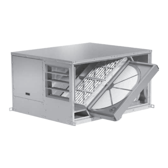
Document 476412
Model ERV
Energy Recovery Ventilator
1
Advertisement
Table of Contents

Related Manuals for Greenheck ERV Series


Summary of Contents for Greenheck ERV Series
- Page 1 Document 476412 Model ERV Energy Recovery Ventilators ® Installation, Operation and Maintenance Manual Please read and save these instructions for future reference. Read carefully before attempting to assemble, install, operate or maintain the product described. Protect yourself and others by observing all safety information. Failure to comply with these instructions will result in voiding of the product warranty and may result in personal injury and/or property damage.
-
Page 2: Table Of Contents
Table of Contents Unit Overview Unit Overview ....2 Basic Unit Receiving, Handling and Storage ..3 The unit is pre-wired such that when a call for outside Installation air is made (via field-supplied 24 VAC control signal... -
Page 3: Receiving, Handling And Storage
Receiving The unit should be stored at least 3½ in. (89 mm) off the floor. Clearance should be provided to permit air This product may have been subject to road salt circulation and space for inspection. during transit. If so, immediately wash off all visible Outdoor white reside from all exterior surfaces. -
Page 4: Installation
Installation ERV-10, ERV-20 and ERV-45 Indoor Mounting Options RETURN RETURN AIR INTAKE AIR INTAKE EXHAUST AIR DISCHARGE SUPPLY AIR SUPPLY AIR DISCHARGE DISCHARGE EXHAUST AIR DISCHARGE OUTDOOR OUTDOOR AIR INTAKE AIR INTAKE Exhaust Air Discharge End Exhaust Air Discharge Side ERV-10, ERV-20 and ERV-45 Outdoor Mounting Options RETURN RETURN... - Page 5 Installation ERV-90 and ERV-120 Indoor Mounting Options SUPPLY AIR SUPPLY AIR DISCHARGE DISCHARGE RETURN AIR RETURN AIR INLET INLET OUTDOOR AIR INLET OUTDOOR AIR INLET EXHAUST AIR DISCHARGE EXHAUST AIR DISCHARGE Exhaust Air Discharge End Exhaust Air Discharge Side ERV-90 and ERV-120 Outdoor Mounting Options SUPPLY AIR SUPPLY AIR DISCHARGE...
-
Page 6: Service Clearances
WHEEL CASSETTE Service Clearances Recommended Service Clearances Units require minimum clearances to perform routine Bolt on Access Hinged Access SUPPLY OUTDOOR Unit Size maintenance, such as filter replacement, energy FILTERS AIR HOOD wheel cassette inspection, and fan belt adjustment. ERV-10 Blower and motor assemblies, energy recovery wheel ERV-20 cassette and filter sections are always provided with... - Page 7 ERV-90 and ERV-120 ACCESS DOOR ACCESS DOOR ACCESS DOORS ACCESS DOOR ACCESS DOOR ACCESS DOORS ELECTRICAL ELECTRICAL OUTDOOR AIR HOOD OUTDOOR AIR HOOD ACCESS DOOR ACCESS DOOR ACCESS DOOR ACCESS DOOR ACCESS DOOR ACCESS DOOR EXHAUST AIR HOOD EXHAUST AIR HOOD Side Exhaust Discharge ACCESS DOOR ACCESS DOOR...
-
Page 8: Access Panel Locations
Access Panel Locations ERV-10, ERV-20 and ERV-45 ERV-90 and ERV-120 OUTDOOR OUTDOOR AIR INTAKE AIR INTAKE Exhaust Air Discharge End Exhaust Air Discharge End OUTDOOR OUTDOOR AIR INTAKE AIR INTAKE Exhaust Air Discharge Side Exhaust Air Discharge Side Outdoor air intake damper Outdoor air intake damper Preheater and controls Preheater and controls... -
Page 9: Handling
Handling Recommended Roof Openings & Weights While this unit was constructed with quality and Position the unit roof opening such that the supply dependability in mind, damage still may occur during discharge and exhaust inlet of the unit will line up with handling of the unit for installation. -
Page 10: Roof Curb Mounting
Roof Curb Mounting Roof curb details including duct location dimensions, Base Side of Unit are available on ERV Roof Curb Assembly Instructions. Rooftop units require curbs to be mounted first. The duct connections must be located so they will be clear of structural members of the building. -
Page 11: Rail Mounting / Layout
Rail Mounting / Layout 1. Rails designed to handle the weight of the ERV should be positioned as shown on the diagram (rails by others). 2. Make sure that rail positioning does not interfere with the supply air discharge opening or the exhaust air intake opening on the ERV unit. -
Page 12: Electrical Information
Electrical Information WARNING The unit must be electrically grounded in accordance To prevent injury or death due to electrocution with the current National Electrical Code, ANSI/NFPA or contact with moving parts, lock disconnect 70. In Canada, use current CSA Standard C22.1, switch open. -
Page 13: Control Center Components
Typical Control Center Components 1. Main disconnect (non-fusible, lockable) 2. Distribution block 3. 24 VAC control transformer 4. Fuses 5. VFD blower or contactor without VFD 6. VFD wheel or contactor without VFD 7. BMS controller 8. Outdoor airflow monitor 9. -
Page 14: Optional Accessory Wiring Schematics
Optional Accessory Wiring Schematics Dirty Filter Indicator Remote Panel (powered by others) The remote panel is available with a number of different alarm lights and switches to control the unit. The remote DIRTY FILTER INDICATOR panel ships loose and requires mounting and wiring in the field. -
Page 15: Optional Component Overview
Optional Component Overview occurring. Both the pressure sensor and the outdoor air Economizer thermodisc must trigger in order to initiate frost control. The energy wheel operation can be altered to take The two sensors together ensure that frost control is advantage of economizer operation (free cooling). -
Page 16: Rotation Sensor
Rotation Sensor The rotation sensor monitors energy wheel rotation. If the wheel should stop rotating, the sensor will close a set of contacts in the unit control center. Field-wiring of a light (or other alarm) between terminals R and 12 in the unit control center will notify maintenance personnel when a failure has occurred. -
Page 17: Start-Up
Start-Up o Rotate the fan wheels and energy recovery wheels by hand and ensure no parts are rubbing. If rubbing occurs, refer to Start-Up Components for more DANGER information. Electric shock hazard. Can cause injury or death. o Check the fan belt drives for proper alignment and Before attempting to perform any service or tension (refer to Start-Up Components for more maintenance, turn the electrical power to unit to OFF... -
Page 18: Optional Accessories Checklists
Optional Accessories Checklists Refer to the respective sections in this Installation, Operation and Maintenance Manual for detailed information. Refer to wiring diagram in unit control center to determine what electrical accessories were provided. Provided with Unit? Frost Control Application / Operation section: Setting Factory Default Frost Control set point... -
Page 19: Start-Up Components Fans
CORRECT changed (speed, pressure, temperature, etc.), consult Direction of Fan Wheel Rotation Greenheck to determine if the unit can operate safely at the new conditions. Blower access is labeled on unit. Check for proper wheel rotation by momentarily energizing the fan. -
Page 20: Vibration
Vibration Air Seals Excessive vibration may be experienced during initial Check that the air seals located around the outside of start-up. Left unchecked, excessive vibration can cause the wheel and across the center (both sides of wheel) a multitude of problems, including structural and/ are secure and in good condition. -
Page 21: Economizer
Economizer Relevant Set Points 1. MAT SET The mixed air temperature set point The table shows which set points are relevant to the after the energy wheel. The control will modulate given sequences. Refer to the wiring diagram for the the energy wheel to maintain temperature as best units’s sequence. -
Page 22: Frost Control
Frost Control Variable Frequency Drives Optional factory installed, wired, and programmed Timed Exhaust variable frequency drives (VFDs) may have been 1. Remove power from unit. provided for modulating or multi-speed control of the 2. Jumper the frost indicating wheel pressure switch in blowers and energy recovery wheel for economizer and the unit control center. - Page 23 Most of the set points in the VFDs are Yaskawa factory defaults. However, C6-02 Carrier Frequency a few set points are changed at Greenheck and are D1-01 Frequency Reference 1 60 Hz 60 Hz shown in the tables.
-
Page 24: Variable Frequency Drives
VARIABLE FREQUENCY DRIVES PROPORTIONAL CONTROL FOR ENERGY RECOVERY WHEEL Setting Parameter Setting – J1000 Parameter V1000 J1000 A1-01 Access Level B1-17 VFD Start-Up Setting B1-17 VFD Auto Start C1-04 Decel Time C6-02 Carrier Frequency *C4-01 Torque Gain D2-02 Ref Lower Limit C6-02 Carrier Frequency E2-01... -
Page 25: Routine Maintenance
Routine Maintenance Dampers Check all dampers to ensure they open and close DANGER properly and without binding. Backdraft dampers can be checked by hand to determine if blades open Electric shock hazard. Can cause injury or death. and close freely. Apply power to motorized dampers Before attempting to perform any service or to ensure the actuator opens and closes the damper maintenance, turn the electrical power to unit to OFF... - Page 26 Fan Wheel & Fasteners Pleated Filter Size and Quantities Wheels require very little attention when moving clean Supply Exhaust Unit Size Size air. Occasionally oil and dust may accumulate on the Qty. Qty. wheel causing imbalance. When this occurs, the wheel ERV-10 16 x 25 and housing should be cleaned to assure smooth and...
- Page 27 Accessing the Energy Recovery Wheel in Removing the Energy Recovery Wheel in Models ERV-90 and 120 ERV-10 Disconnect power to the ERV. Remove access panel(s) First, remove the drive belts and the collars in both labeled “Energy Wheel Cassette Access”, which bearings.
-
Page 28: Troubleshooting Economizer Alarms
If a belt requires replacement, contact Wheel Belt & Pulley the local Greenheck representative. Instructions for replacement will ship with the new belt. Energy Recovery Wheel Bearing In the unlikely event that... -
Page 29: Airflow
Troubleshooting – Airflow Test and Balance Report The Test and Balance Report (TAB) is utilized to determine whether the appropriate amount of outdoor air and exhaust air is being supplied and removed from a building, respectively. There are no set rules on what information must be included in a TAB report. -
Page 30: Unit
Troubleshooting – Unit Symptom Possible Cause Corrective Action Replace fuse or reset circuit breaker and Blown fuse or open circuit breaker. check amps. Defective motor or capacitor. Replace. Blower fails to Motor starter overloaded. Reset starter and check amps. operate Check for On/Off switches. - Page 31 Troubleshooting – Unit Symptom Possible Cause Corrective Action One or both blowers turn off Exhaust Only frost control sensors are Adjust frost temperature sensor set point as intermittently and tripping. needed. back on after about 2 minutes See Energy Recovery Wheel under Unit Air seals are too tight.
-
Page 32: Maintenance Log
As a result of our commitment to continuous improvement, Greenheck reserves the right to change specifications without notice. Product warranties can be found online at Greenheck.com, either on the specific product page or in the literature section of the website at Greenheck.com/Resources/Library/Literature.