Table of Contents
Advertisement
145W + 145W (8Ω) RMS Output Power, 0.01% THD, 20-20,000 Hz
110W + 110W (8Ω) RMS Output Power, 0.015% THD, 20-20,000 Hz
PURE DIRECT Switch to Reproduce the Purest Source Sound
PRE OUT/MAIN IN Terminals Useful for Connecting An Equalizer,
Turnover Frequency Switch for Tone Controls
Thank you for selecting this YAMAHA stereo integrated amplifier.
OWNER'S MANUAL
CONTENTS
Safety Instructions ................... 2
Supplied Accessories .............. 3
Connections ............................. 4
Operations ............................... 6
Remote Control Transmitter ... 10
Control Transmitter ................. 11
Troubleshooting ...................... 12
Specifications ......................... 13
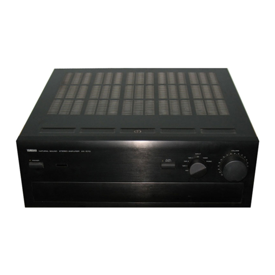
AX -1070/870
Natural Sound Stereo Integrated Amplifier
Increased Low Impedance Drive Capability
Continuously Variable Loudness Control
SUBSONIC FILTER Switch to Cut Out Undesirable
IMPORTANT!
Please record the serial number of this
unit in the space below.
Model:
Serial No.:
The serial number is located on the rear
of the unit.
Retain this Owner's Manual in a safe
place for future reference.
WARNING
TO REDUCE THE RISK OF FIRE OR
ELECTRIC SHOCK, DO NOT EXPOSE
THIS UNIT TO RAIN OR MOISTURE.
Ultra-Low-Frequency Signals
Sound Processor, etc.
<
For AX-1070 only
High Quality Components Parts
Remote Control Capability
CAUTION: TO REDUCE THE RISK OF
ELECTRIC SHOCK, DO NOT REMOVE
COVER (OR BACK), NO USER-SERVICEABLE
PARTS INSIDE, REFER SERVICING TO
QUALIFIED SERVICE PERSONNEL.
• Explanation of Graphical Symbols
<
>
AX-1070
<
>
AX-870
>
CAUTION
RISK OF ELECTRIC SHOCK
DO NOT OPEN
The lightning flash with arrowhead
symbol, within an equilateral triangle,
is intended to alert you to the
presence of uninsulated "dangerous
voltage" within the product's
enclosure that may be of sufficient
magnitude to constitute a risk of
electric shock to persons.
The exclamation point within an
equilateral triangle is intended to alert
you to the presence of important
operating and maintenance
(servicing) instructions in the
literature accompanying the
appliance.
Advertisement
Table of Contents

Related Manuals for Yamaha AX-1070


Summary of Contents for Yamaha AX-1070
-
Page 1: Table Of Contents
PURE DIRECT Switch to Reproduce the Purest Source Sound PRE OUT/MAIN IN Terminals Useful for Connecting An Equalizer, Turnover Frequency Switch for Tone Controls Thank you for selecting this YAMAHA stereo integrated amplifier. OWNER’S MANUAL CONTENTS Safety Instructions ... 2 Supplied Accessories ... -
Page 2: Safety Instructions
SAFETY INSTRUCTIONS Read Instructions – All the safety and operating instructions should be read before the unit is operated. Retain Instructions – The safety and operating instructions should be retained for future reference. Heed Warnings – All warnings on the unit and in the operating instructions should be adhered to. -
Page 3: Supplied Accessories
This product, when installed as indicated in the instructions contained in this manual, meets FCC requirements. Modifications not expressly approved by Yamaha may void your authority, granted by the FCC, to use the product. 2. IMPORTANT : When connecting this product to accessories and/or another product use only high quality shielded cables. -
Page 4: Connections
When making connections between this unit and other components, be sure all connections are made correctly, that is to say L (left) to L, R (right) to R, “+” to “+” and “–” to “–”. Also, refer to the owner’s manual for each component to be connected to this unit. < > AX-1070 Compact disc player Tuner Turntable Video cassette player, LD player, etc. - Page 5 < > AX-870 Tuner Compact disc player Tape deck 1 Tape deck 2 Speakers A Left Right (General model) To AC outlet Left Right Speakers B Turntable Video cassette player, LD player, etc. : Refer to “ABOUT THE ACCESSORY TERMINALS” on page 6.
- Page 6 OUTLETS is 200 watts. REMOTE CONTROL (PHONO) connector If you have a YAMAHA turntable with a terminal for remote control, connect it to this connector by using the cable provided with the turntable. This connection allows you to control the turntable from the provided remote control transmitter.
-
Page 7: Operations
Illustration: AX-1070 Parts in shaded area ( are not present on AX-870. PHONES TO PLAY A SOURCE ∞ Set to the “ ” position. POWER Select a desired input source. < > AX-1070 * If you select turntable as an input source (PHONO position), refer to “Setting the PHONO switch”... - Page 8 Illustration: AX-1070 Parts in shaded area ( are not present on AX-870. TO RECORD A SOURCE TO TAPE (OR DUB FROM A TAPE TO ANOTHER) Select the source to be recorded. < > AX-1070 REC OUT TUNER TAPE COPY PHONO Play the source.
- Page 9 REC OUT selector setting on tape dubbing < > AX-1070 To dub from tape deck 1 to tape deck 2 or 3 (or both tape deck 2 and 3 at the TAPE COPY same time) To dub from tape deck 3 to...
-
Page 10: Selecting The Speaker System
This control is adjustable to retain full tonal range at any volume level. TREBLE DEFEAT < > For AX-1070 only 5kHz Selecting the SPEAKER system SPEAKERS Adjusting the continuously variable LOUDNESS control LOUDNESS Set to the “FLAT”... - Page 11 MC cartridge, select MM position. PHONO Setting the MODE switch < For AX-1070 only This switch can be used for switching between stereo and monaural operation. Normally this switch should be set to the STEREO position.
-
Page 12: Remote Control Transmitter
The remote control transmitter provided with this unit is designed to control all the most commonly used functions of the unit. If the CD player, tuner, turntable, equalizer, and tape deck connected to this unit are YAMAHA components, then this remote control transmitter will also control various functions of each component. -
Page 13: Notes About The Remote Control Transmitter
STANDBY mode (For Europe model only) While the power is on, pressing the POWER key on the remote control transmitter switches the unit to the STANDBY mode. (In this mode, the indicator is half illuminated.) Note To turn the power off completely, disconnect the AC power plug from the wall outlet. -
Page 14: Troubleshooting
If the unit fails to operate normally, check the following points to determine whether the fault can be corrected by the simple measures suggested. If it cannot be corrected, or if the fault is not listed in the SYMPTOM column, disconnect the power cord and contact your authorized YAMAHA dealer or service center for help. SYMPTOM The unit fails to turn on when the POWER switch is pressed. -
Page 15: Specifications
< > AX-870 ...–30 dB (1 kHz) < > Audio Muting AX-1070 only ...–20 dB Gain Tracking Error (0 to –60 dB) ...2 dB Power Supply [Australia and U.K. models] ...AC 240V, 50 Hz [Europe model]...AC 230V, 50 Hz [General model] ...AC 110/120/220/240V, 50/60 Hz... - Page 16 YAMAHA ELECTRONIQUE FRANCE S.A. RUE AMBROISE CROIZAT BP70 CROISSY-BEAUBOURG 77312 MARNE-LA-VALLEE CEDEX02, FRANCE YAMAHA ELECTRONICS (UK) LTD. YAMAHA HOUSE, 200 RICKMANSWORTH ROAD WATFORD, HERTS WD1 7JS, ENGLAND YAMAHA SCANDINAVIA A.B. J A WETTERGRENS GATA 1, BOX 30053, 400 43 VÄSTRA FRÖLUNDA, SWEDEN 0000000...