Table of Contents
Advertisement
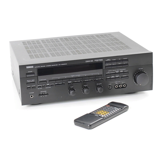
RX-V590RDS
Natural Sound Stereo Receiver
Récepteur stéréo "Son Naturel"
Natural Sound Stereoreceiver
Natural Sound Stereoreceiver
Sintonizzatore stereo a suono naturale
Receptor estéreo de Sonido Natural
Natural Sound Stereo Ontvanger
OWNER'S MANUAL
MODE D'EMPLOI
BEDIENUNGSANLEITUNG
BRUKSANVISNING
MANUALE DI ISTRUZIONI
MANUAL DE INSTRUCCIONES
GEBRUIKSAANWIJZING
Advertisement
Table of Contents

Related Manuals for Yamaha RX-V590RDS


Summary of Contents for Yamaha RX-V590RDS
- Page 1 RX-V590RDS Natural Sound Stereo Receiver Récepteur stéréo “Son Naturel” Natural Sound Stereoreceiver Natural Sound Stereoreceiver Sintonizzatore stereo a suono naturale Receptor estéreo de Sonido Natural Natural Sound Stereo Ontvanger OWNER’S MANUAL MODE D’EMPLOI BEDIENUNGSANLEITUNG BRUKSANVISNING MANUALE DI ISTRUZIONI MANUAL DE INSTRUCCIONES...
-
Page 2: Supplied Accessories
SUPPLIED ACCESSORIES ACCESSOIRES FOURNIS MITGELIEFERTE ZUBEHORTEILE MEDFOLJANDE TILLBEHOR ACCESSORI IN DOTAZIONE ACCESORIOS INCLUIDOS BIJGELEVERDE ACCESSOIRES Indoor FM Antenna Antenne FM intérieure UKW-Innenantenne FM inomhusantenn Antenna FM per interni Antena FM interior FM Binnenantenne AM Loop Antenna Cadre-antenna AM MW-Rahmenantenne AM ramantenn Antenna AM ad anello Antena de cuadro de AM AM Lusantenne... -
Page 3: Table Of Contents
Thank you for selecting this YAMAHA stereo receiver. FEATURES 5 Speaker Configuration Front: 70W + 70W (8Ω) RMS Output Power, 0.04% THD, 20–20,000 Hz Center: 70W (8Ω) RMS Output Power, 0.07% THD, 1 kHz Rear: 20W + 20W (8Ω) RMS Output Power, 0.3% THD, 1 kHz... -
Page 4: Caution
CAUTION : READ THIS BEFORE OPERATING YOUR UNIT. To assure the finest performance, please read this manual carefully. Keep it in a safe place for future reference. Install this unit in a cool, dry, clean place – away from windows, heat sources, sources of excessive vibration, dust, moisture and cold. -
Page 5: Profile Of This Unit
You are the proud owner of a Yamaha stereo receiver –an extremely sophisticated audio component. The Digital Sound Field Processor (DSP) built into this unit takes full advantage of Yamaha’s undisputed leadership in the field of digital audio processing to bring you a whole new world of listening experiences. -
Page 6: Speaker Setup For This Unit
SPEAKER SETUP FOR THIS UNIT SPEAKERS TO BE USED This unit is designed to provide the best sound-field quality with a 5 speaker configuration. The speakers to be used with this unit will be mainly front speakers, rear speakers, and a center speaker. (You can omit the center speaker. Refer to the “4-Speaker Configuration”... -
Page 7: Connections
Before attempting to make any connections to or from this unit, be sure to first switch OFF the power to this unit and to any other components to which connections are being made. CONNECTIONS WITH OTHER COMPONENTS When making connections between this unit and other components, be sure all connections are made correctly, that is to say L (left) to L, R (right) to R, “+”... - Page 8 CONNECTING TO S VIDEO TERMINALS If you have a video cassette recorder and a monitor equipped with “S” (high-resolution) video terminals, those terminals can be connected to this unit’s S VIDEO terminals. Connect the video cassette recorder’s “S” video input and output terminals to this unit’s S VIDEO VCR 2 IN and OUT terminals respectively, and connect the monitor’s “S”...
-
Page 9: Connecting Speakers
CONNECTING SPEAKERS Connect the respective speakers to this unit as figured below. Center speaker Note on front speaker connection: One or two speaker systems can be connected to this unit. If you connect only one speaker system, connect it to either the SPEAKERS A or B terminals. - Page 10 How to Connect: Connect the SPEAKERS terminals to your speakers with wire of the proper gauge, cut as short as possible. If the connections are faulty, no sound will be heard from the speakers. Make sure that the polarity of the speaker wires is correct, that is, + and –...
- Page 11 Connect the LOW PASS terminal to the INPUT terminal of the subwoofer amplifier, and connect the speaker terminals of the subwoofer amplifier to the subwoofer. With some subwoofers, including the Yamaha Active Servo Processing Subwoofer System, the amplifier and subwoofer are in the same unit.
-
Page 12: Antenna Connections
ANTENNA CONNECTIONS Each antenna should be connected to the designated terminals correctly, referring to the following diagram. Both AM and FM indoor antennas are included with this unit. In general, these antennas will probably provide sufficient signal strength. Nevertheless, a properly installed outdoor antenna will give clearer reception than an indoor one. If you experience poor reception quality, an outdoor antenna may result in improvement. -
Page 13: Speaker Balance Adjustment
SPEAKER BALANCE ADJUSTMENT This procedure lets you adjust the sound output level balance between the front, center, and rear speakers using the built-in test tone generator. With this adjustment, the sound output level heard at the listening position will be the same from each speaker. This is important for the best performance of the digital sound field processor. - Page 14 Select the center channel output mode according to your speaker configuration. (Refer to “SPEAKER CONFIGURATION” on page 6.) CENTER MODE On the feature of each mode, refer to the “Note” shown below. Note In step 6, when you select the center channel output mode, note the following.
- Page 15 Adjust the BALANCE control so that the effect sound output level of the left front speaker and the right front speaker are the same. BALANCE Adjust the sound output level of the center speaker to be at the same level as that of the front speakers with the CENTER LEVEL keys.
-
Page 16: Basic Operations
TO PLAY A SOURCE ∞ Set to the “ POWER Select the desired input source by using the input selector buttons. (For video sources, turn the TV/monitor ON.) TAPE MONITOR TUNER VIDEO AUX VCR 2 VCR 1 * The name of the selected input source will appear in the display. - Page 17 TO RECORD A SOURCE TO TAPE (OR DUB FROM TAPE TO TAPE) Select the source to be recorded. TAPE MONITOR TUNER VIDEO AUX VCR 2 VCR 1 Play the source and then turn the VOLUME control up to confirm the input source. (For detailed information on the tuning operations, refer to page 19.) Set the tape deck or VCR to the recording mode.
-
Page 18: Selecting The Speaker System
Selecting the SPEAKER system Because one or two speaker systems (as front speakers) can be connected to this unit, the SPEAKERS switches allow you to select speaker system A or B, or both at once. SPEAKERS Adjusting the BALANCE control Adjust the balance of the output volume to the left and right speakers to compensate for sound imbalance caused by speaker location or listening room conditions. -
Page 19: Tuning Operations
Normally, if station signals are strong and there is no interference, quick automatic-search tuning (AUTOMATIC TUNING) is possible. However, if signals of the station you want to select are weak, you must tune to it manually (MANUAL TUNING). AUTOMATIC TUNING Select the reception band (FM or AM) while watching the display. -
Page 20: Preset Tuning
MANUAL PRESET TUNING This unit can store station frequencies (selected by tuning operation) by using the preset station buttons. With this function, you can select any desired station by only pressing the corresponding preset station button. Up to 40 stations (8 stations x 5 pages) can be stored. - Page 21 AUTOMATIC PRESET TUNING You can also make use of an automatic preset tuning function for RDS stations only. By this function, this unit performs automatic tuning and stores RDS stations with strong signals sequentially. Up to 40 stations are stored automatically in the same way as in the manual preset tuning method on page 20.
-
Page 22: Exchanging Preset Stations
EXCHANGING PRESET STATIONS You can exchange the places of two preset stations with each other as shown below. 2, 4 Example) If you want to shift the preset station on E1 to A5, and vice versa. Recall the preset station on E1 (by following the method of “To recall a preset station”... -
Page 23: Receiving Rds Stations
RECEIVING RDS STATIONS RDS (Radio Data System) is a data transmission system gradually being introduced by FM stations in many countries. Stations using this system transmit an inaudible stream of data in addition to the normal radio signal. RDS data contains various information, such as AF (Alternative Frequencies for the same program station), PI (Program Identification), PS (Program Service station name), PTY (Program Type name), etc. - Page 24 To turn the unit into the PS mode or PTY mode Press the FREQ/PS/PTY button. Whenever pressed, the mode changes into the PS mode, PTY mode and returns to usual mode in turn. * When an RDS station is received, the display is automatically turned into the PS mode. Do not press the FREQ/PS/PTY button until the display is turned into the PS mode.
- Page 25 Calling a preset RDS station by the station name (PS SEEK) You can call a desired RDS station stored in this unit by only inputting the name of the station in the PS mode. By this operation, this unit searches all preset stations for the station. You do not have to input a full name, even only the first letter can be used for calling.
- Page 26 Calling a preset RDS station by the program type (PTY SEEK) By designating a program type, the unit automatically searches all preset stations for RDS stations of that program type. * There are 15 program types to classify RDS stations. For details, refer to page 23. Turn the unit into the PTY mode.
-
Page 27: Using Digital Sound Field Processor (Dsp)
USING DIGITAL SOUND FIELD PROCESSOR (DSP) This unit incorporates a sophisticated, multi-program digital sound field processor, which allows you to expand and shape the audio sound field from both the audio and video sources, for a theater-like experience in the listening/viewing room. This digital sound field processor has 8 programs;... - Page 28 Description of Each Sound Field Program The following list gives brief descriptions of the sound fields produced by each of the DSP programs. Keep in mind that most of these are precise digital recreations of actual acoustic environments. The data for them was recorded at the locations described using sophisticated sound field measurement equipment.
- Page 29 To play a source with the digital sound field processor Follow steps 1 – 6 shown in “BASIC OPERATIONS” on page 16. Select the desired program that is suitable for the source. DIGITAL SOUND FIELD PROCESSOR CONCERT MONO PRO LOGIC ENHANCED VIDEO MOVIE ROCK...
- Page 30 Adjustment of the REAR LEVEL If desired, you can adjust the sound output level of the rear speakers even if the output level is already set in “SPEAKER BALANCE ADJUSTMENT” on page 15. REAR LEVEL Adjustment of DELAY TIME You can adjust the time difference between the beginning of the source sound and the beginning of the effect sound with the DELAY TIME control.
-
Page 31: Setting The Sleep Timer
SETTING THE SLEEP TIMER If you use the SLEEP timer of this unit, you can make this unit turn off automatically. When you are going to sleep while enjoying a broadcast or other desired input source, this timer function is helpful. Notes The SLEEP timer can be controlled only with the remote control transmitter. -
Page 32: Remote Control Transmitter
The remote control transmitter provided with this unit is designed to control all the most commonly used functions of the unit. If the CD player and tape deck connected to this unit are YAMAHA components, then this remote control transmitter will also control various functions of each component. -
Page 33: Notes About The Remote Control Transmitter
STANDBY mode While the power is on, pressing the POWER key on the remote control transmitter switches the unit to the STANDBY mode. (In this mode, the indicator is half illuminated.) NOTES ABOUT THE REMOTE CONTROL TRANSMITTER Battery installation Battery replacement If you find that the remote control transmitter must be used closer to the main unit, the batteries are weak. -
Page 34: Troubleshooting
If the unit fails to operate normally, check the following points to determine whether the fault can be corrected by the simple measures suggested. If it cannot be corrected, or if the fault is not listed in the SYMPTOM column, disconnect the power cord and contact your authorized YAMAHA dealer or service center for help. SYMPTOM The unit fails to turn on when the POWER switch is pressed. -
Page 35: Specifications
SPECIFICATIONS AUDIO SECTION Minimum RMS Output Power per Channel Front L, R 8 ohms, 20 Hz to 20 kHz, 0.04% THD ...70W+70W Center 8 ohms, 1 kHz, 0.07% THD ...70W Rear L, R 8 ohms, 1 kHz, 0.3% THD...20W+20W Dynamic Power per Channel (by IHF Dynamic Headroom measuring method) 8/6/4/2 ohms ...95/120/150/170W... - Page 36 YAMAHA ELECTRONIQUE FRANCE S.A. RUE AMBROISE CROIZAT BP70 CROISSY-BEAUBOURG 77312 MARNE-LA-VALLEE CEDEX02, FRANCE YAMAHA ELECTRONICS (UK) LTD. YAMAHA HOUSE, 200 RICKMANSWORTH ROAD WATFORD, HERTS WD1 7JS, ENGLAND YAMAHA SCANDINAVIA A.B. J A WETTERGRENS GATA 1, BOX 30053, 400 43 VÄSTRA FRÖLUNDA, SWEDEN VT04810...