Baxi Assure Mono 5 Installation And Owner's Manual
Heat pump air/water "inverter"
Hide thumbs
Also See for Assure Mono 5:
- Operation user's manual (32 pages) ,
- Installation and owner's manual (100 pages)

Related Manuals for Baxi Assure Mono 5


Summary of Contents for Baxi Assure Mono 5
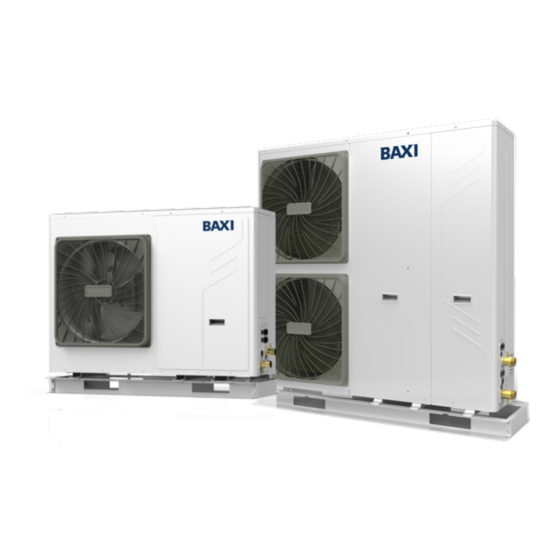
- Page 1 Installation and owner’s manual Heat Pump air/water "inverter" Assure Mono 5 Assure Mono 7 Assure Mono 9 Assure Mono 12 Assure Mono 16...
-
Page 2: Table Of Contents
CONTENTS SAFETY CONSIDERATIONS GENERAL INFORMATION ACCESSORIES BEFORE INSTALLATION IMPORTANT INFORMATION FOR THE REFRIGERANT INSTALLATION SITE INSTALLATION PRECAUTIONS TYPICAL APPLICATIONS OVERVIEW OF THE UNIT START-UP AND CONFIGURATION... - Page 3 TEST RUN AND FINAL CHECKS MAINTENANCE AND SERVICE TROUBLE SHOOTING TECHNICAL SPECIFICATIONS 15 INFORMATION SERVICING Description of terms...
- Page 4 This product is a MCS register product under BAXI brand.
- Page 6 NOTE...
- Page 7 1 SAFETY PRECAUTIONS INFORMATION WARNING DANGER WARNING CAUTION NOTE Explanation of symbols displayed on the indoor unit or outdoor unit...
- Page 8 DANGER WARNING CAUTION : : :...
- Page 9 NOTE 2 GENERAL INTRODUCTION...
-
Page 11: Accessories
3 ACCESSORIES 3.1 Accessories supplied with the unit ( ) 3.2 Accessories available from supplier 4 BEFORE INSTALLATION Before installation Handling... -
Page 12: Important Information For The Refrigerant
CAUTION NOTE 5 IMPORTANT INFORMATION FOR THE REFRIGERANT... -
Page 13: Installation Site
CAUTION 6 INSTALLATION SITE WARNING... - Page 14 NOTE 6.1 Selecting a location in cold climates NOTE 6.2 Selecting a location in hot climates...
-
Page 15: Installation Precautions
7 INSTALLATION PRECAUTIONS 7.1 Dimensions 7.2 Installation requirements... - Page 16 7.3 Drain hole position NOTE 7.4 Servicing space requirements 7.4.1 In case of stacked installation 7.4.2 In case of multiple-row installation (for roof top use, etc.)
- Page 17 < <...
-
Page 18: Typical Applications
8 TYPICAL APPLICATIONS 8.1 Application 1 ( ) NOTE : NOTE... - Page 19 8.2 Application 2 ( ) NOTE Circulation pump operation Space heating Domestic water heating...
- Page 20 CAUTION NOTE 8.3 Application 3 ( )...
- Page 21 NOTE Pump operation and space heating and cooling CAUTION Domestic water heating 8.4 Application 4...
- Page 22 ( ) NOTE Pump operation NOTE Space heating and cooling CAUTION 8.5 Application 5...
- Page 23 CAUTION 8.5.1 Application a 8.5.2 Application b...
- Page 24 8.5.3 Application c ( ) NOTE Operation...
- Page 25 NOTE CAUTION 8.6 Application 6 NOTE...
- Page 26 ( ) NOTE Pump operation and space heating...
- Page 27 NOTE 8.7 Application 7...
- Page 28 ( ) NOTE Pump operation and space heating 8.8 Application 8...
-
Page 29: Overview Of The Unit
( ) NOTE NOTE 9 OVERVIEW OF THE UNIT 9.1 Disassembling the unit... - Page 30 WARNING 9.2 Main components 9.2.1 Hydraulic module...
- Page 31 9.2.2 Hydraulic system diagram...
- Page 32 NOTE 9.3 Electronic control box...
- Page 33 9.3.1 Main control board of hydraulic module...
- Page 34 9.3.2 1-phase for 5/7/9kW units ,...
- Page 35 9.3.3 1-phase for 12/16 kW units ,...
- Page 36 9.3.4 3-phase for 12/16 kW units ,...
- Page 38 9.3.5 Controls parts for backup heater(Reserved)
- Page 39 9.4 Water piping 9.4.1 Check the water circuit : NOTE...
- Page 40 9.4.2 Water volume and expansion vessel pre-pressure checks NOTE Calculating the pre-pressure of the expansion vessel Checking the maximum allowed water volume...
- Page 41 9.4.3 Water circuit connection CAUTION Example 1: Example 2: NOTE...
- Page 42 9.4.4 Water circuit anti-freeze protection WARNING...
- Page 43 NOTE 9.5 Adding water CAUTION NOTE NOTE...
- Page 44 NOTE 9.6 Water piping insulation 9.7 Field wiring WARNING 9.7.1 Precautions on electrical wiring work NOTE...
- Page 45 9.7.2 Wiring overview...
- Page 46 NOTE...
- Page 47 WARNING 9.7.3 Precautions on wiring of power supply...
- Page 48 9.7.4 Specifications of standard wiring components NOTE 9.7.5 Connection of the backup heater power supply CAUTION ( ) NOTE...
- Page 49 9.7.6 Connection for other components : : Two kind of control signal port 1) For solar energy kit...
- Page 50 NOTE 2) For 2-way valve SV2: a) Procedure 5) For remote shut down: NOTE 6) For tank loop pump P_d and mix pump P_c: a) Procedure NOTE 3) For 3-way value SV3 4) For 3-way value SV1 , , a) Procedure...
- Page 51 7) For room thermostat: NOTE...
- Page 52 Method A : Method B : NOTE Method C NOTE a) Procedure 8) For booster heater: a) Procedure...
- Page 53 9) For additional heat source control: 12) For defrosting signal output: , 10) For outside circulation pump P_o: 13) For wired controller: a) Procedure 11) For external backup heater kit NOTE...
- Page 54 a) Procedure 14) For smart grid (installations only): ℃...
-
Page 55: Start-Up And Configuration
10 START-UP AND CONFIGURATION CAUTION 10.1 Climate related curves NOTE... - Page 56 ℃ ℃ ℃...
- Page 57 ℃ 10.2 DIP switch settings overview 10.2.1 Function setting WARNING 10.3 Initial start-up at low outdoor ambient temperature 10.4 Pre-operation checks...
- Page 58 DANGER : : : : : : : : : : : 10.5 Powering up the unit 10.6 Setting the pump speed Ⅲ Ⅱ Ⅰ...
- Page 59 DANGER Ⅲ Ⅱ Ⅰ DANGER 1) Pump LED diagnosis and solutions 2) Failure diagnosis at the moment of first installation...
- Page 60 10.7 Field settings Powering on the unit NOTE About FOR SERVICEMAN How to go to FOR SERVICEMAN 10.7.1 DHW MODE SETTING...
- Page 61 10.7.3 HEAT MODE SETTING 10.7.4 AUTO MODE SETTING 10.7.2 COOL MODE SETTING 10.7.5 TEMP. TYPE SETTING About TEMP. TYPE SETTING How to enter the TEMP. TYPE SETTING...
- Page 63 10.7.6 ROOM THERMOSTAT 10.7.8 HOLIDAY AWAY SETTING About ROOM THERMOSTAT How to set the ROOM THERMOSTAT 10.7.9 SERVICE CALL SETTING NOTE 10.7.7 Other HEATING SOURCE...
- Page 64 10.7.10 RESTORE FACTORY SETTINGS 10.7.11 TEST RUN CAUTION NOTE Before using cooling mode, refer to §2. General introduction...
- Page 65 10.7.12 SPECIAL FUNCTION NOTE...
- Page 67 10.7.14 How to set the 10.7.15 How to set the 10.7.13 AUTO RESTART...
- Page 68 10.7.16 Setting parameters...
- Page 71 10.7.17 Description of terms NOTE 11.2 Test run operation (manually) 12 MAINTENANCE AND SERVICE DANGER 11 TEST RUN AND FINAL CHECKS 11.1 Final checks...
- Page 72 WARNING NOTE 13 TROUBLE SHOOTING 13.1 General guidelines...
- Page 73 13.2 General symptoms...
- Page 75 13.3 Operation parameter 、 NOTE...
- Page 76 13.4 Error codes ( )...
- Page 78 ,...
- Page 79 ( )...
- Page 81 ( )...
- Page 82 14 TECHNICAL SPECIFICATIONS 14.1 General 14.2 Electrical specifications 14.3 Sensor specifications...
- Page 83 15 INFORMATION SERVICING...
- Page 84 NOTE...
- Page 87 ANNEX A: Refrigerant cycle Cooling Heating...
- Page 88 ANNEX B: Electrically controlled wiring diagram 1-phase 5/7/9kW...
- Page 89 Annex B: Electrically controlled wiring diagram 1-phase 12/16kW...
- Page 90 Annex B: Electrically controlled wiring diagram 3-phase 12/16kW...
- Page 91 NOTE...
- Page 92 Benchmark Commissioning & Warranty Validation Service Record www.hhic.co.uk This Commissioning Checklist is to be completed in full by the competent person who commissioned the heat pump and associated equipment as a means of demonstrating compliance with the appropriate Building Regulations and then handed to the customer to keep for future reference.
- Page 93 AIR TO WATER HEAT PUMP COMMISSIONING CHECKLIST Electrical and Hydronic Controls – SYSTEM AND HEAT PUMP (Tick the appropriate boxes) Water Treatment – SYSTEM AND HEAT PUMP (Tick the appropriate boxes/Measure and Record) Heat Pump outdoor unit (Tick the appropriate boxes/Measure and Record) CENTRAL HEATING MODE (Tick the appropriate boxes/Measure and Record) DOMESTIC HOT WATER MODE (Tick the appropriate boxes)
- Page 94 ADDITIONAL SYSTEM INFORMATON (Tick the appropriate boxes/Measure and Record) ALL INSTALLATIONS...
- Page 95 Service provider SERVICE 01 SERVICE 02 Signature: Signature: SERVICE 03 SERVICE 04 Signature: Signature: SERVICE 05 SERVICE 06 Signature: Signature:...
- Page 96 Service provider SERVICE 07 SERVICE 08 Signature: Signature: SERVICE 09 SERVICE 10 Signature: Signature:...
- Page 100 FOR UNITED KINGDOM For Baxi Customer Support and Technical Advice, contact us at 0344 871 1545 Please note calls may be monitored or recorded www.baxi.co.uk Open Monday - Friday: 8am - 6pm Weekends & Bank Holidays: 8.30am - 2pm Baxi, Brooks House Coventry Road, Warwick, CV34 4LL.