
Related Manuals for Motorola LXN 500


Summary of Contents for Motorola LXN 500
- Page 1 System Release 1.0 LXN 500 Installation Configuration and Operation Guide DECEMBER 2017 MN003563A01-B © 2017 Motorola Solutions, Inc. All rights reserved...
-
Page 2: Copyrights
Laws in the United States and other countries preserve for Motorola certain exclusive rights for copyrighted computer programs. Accordingly, any copyrighted Motorola computer programs contained in the Motorola products described in this document may not be copied or reproduced in any manner without the express written permission of Motorola. -
Page 3: Contact Us
The page number with the error • A description of the error • We welcome your feedback on this and other Motorola manuals. To take a short, confidential survey on Motorola Customer Documentation, go to docsurvey.motorolasolutions.com or scan the following QR code with your mobile device to access the survey. -
Page 4: Document History
Date MN003563A01-A Release release of the LXN 500 07/2017 MN003563A01-B Update to LXN 500 O&M configuration section 10/2017 FCC Information This device complies with Part 15 of the FCC rules: Operation is subjected of the following two conditions: (1) This device may not cause harmful interference, and (2) This device must accept any interference received, including interference that may cause undesired operation. -
Page 5: Table Of Contents
Powering Off ............................ 18 Starting Shutdown Sequence ....................18 Forcing Power Off ........................18 What is Required for Configuration ....................19 Connecting the LXN 500 to a Laptop ....................19 Signing In ............................20 Viewing System Notifications ......................21 Signing Out ............................21 Account Management ........................ - Page 6 Unpacking ............................47 Configuration Options of Antenna Installation .................. 48 Dome Antenna Configuration ....................48 Dual Diversity Antenna Configuration ..................49 Preparing to Install the LXN 500 ...................... 50 Tools ............................50 Materials ..........................50 Planning ............................50 Ventilation ..........................51 Electrical Guidelines .......................
- Page 7 Connecting the LXN 500 to Power and Ground ..................53 Cable Routing into Engine Compartment ....................53 Installing the Optional Power Protection and Back-up Unit ............... 55 LXN 500 Installed Inside a Trunk of a Vehicle ................... 56 Send Feedback...
- Page 8 Features of LXN 500 Front Panel ......................12 Back Panel Features ..........................16 Management Permissions Assigned to Each User Role in the LXN 500 ..........22 Default Password Assigned to Each User Role ..................23 eNodeB Band Configuration ........................30 iperf Command Line Options ........................
-
Page 9: About Lxn 500
LXN 500 management and solutions to common problems. Helpful Background Information Motorola Solutions offers various courses designed to assist in learning about the system. For information, go to http://www.motorolasolutions.com/training to view the current course offerings and technology paths. - Page 10 MN003563A01-B About LXN 500 Send Feedback...
-
Page 11: Overview
The WAVE 5000 Mobile Communicator enable the mobile devices connected to LXN 500 to a multi-channel Push-To-Talk (PTT) handsets for fully secure, real-time PTT voice communication. WAVE 5000 also connects the LXN 500 subscribers to Land Mobile Radio (LMR) users to provide unified voice, text messaging and presence in a single and easy-to-use application. -
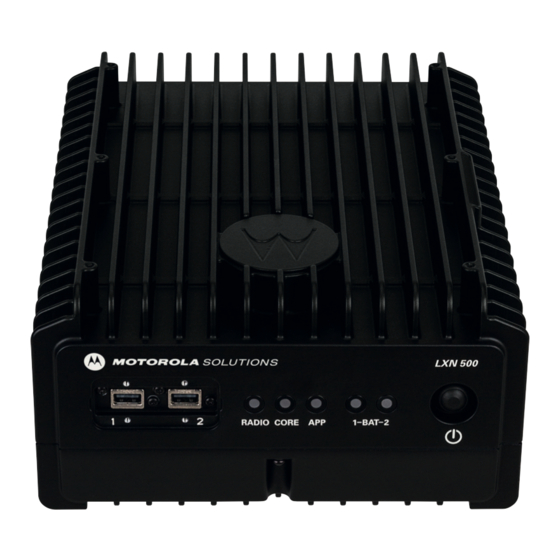
Page 12: Lxn 500 Front Panel Features
To start shutdown sequence; hold pressed for four seconds. To force power off; hold pressed for more than 15 seconds. When the LXN 500 is powered by batteries (Future option of the LXN 500), one second press of the Power button switches between active and standby battery. - Page 13 - Battery is in Standby mode and its capacity is less than 10% • APP is a status LED used to diagnose and troubleshoot the LXN 500. Refer to Troubleshooting and Maintenance whenever the LED shows orange or red color.
- Page 14 BLINKING RED - Fatal Error - No connection to eNodeB board USB 2.0 port for connecting peripheral devices such flash-disks to the LXN 500. The USB port is covered by a protective cover. - To enable a successful boot-up, remove all USB devices connected to the IMPORTANT LXN 500 before powering on.
-
Page 15: Lxn 500 Back Panel Features
1 NET Network (NET) 1 GBit/s LAN port. This port is used for connecting the LXN 500 to a Local Area Network (LAN) infrastructure or an external application server. When maintenance is required, this port enables access to the servers and eNodeB of the LXN 500. - Page 16 MN003563A01-B Overview Send Feedback...
-
Page 17: Operation And Configuration
Obtaining the Unit Identification (UID) Number The Unit Identification (UID) number is required throughout the configuration process of the LXN 500. The UID can be found on the information label at the bottom side of the LXN 500. LXN 500 Information Label... -
Page 18: Powering On
Result: During boot-up, all LEDs blink green for about four minutes and then remain steady green indicating a successful boot. - When using the LXN 500 inside a vehicle, power on only after engine start. IMPORTANT - To enable a successful boot-up, remove all USB devices connected to the LXN 500 before powering on. -
Page 19: What Is Required For Configuration
Default gateway: 10.98.66.<UID> • Connect an Ethernet Cable between the LAN Port of a laptop and the MNG Port on the LXN 500. Connect the Power Supply Unit to the LXN 500. Power on the LXN 500 (See Powering On on page 18). -
Page 20: Signing In
Connecting the LXN 500 to a Laptop on page 19). In the LXN 500 O&M Configuration - Sign In Screen, enter User and the corresponding Password and click Sign In. When signing in for the first time, sign in with the default Administrator password - enter:... -
Page 21: Viewing System Notifications
EPC Tab Figure 2-4 Viewing System Notifications During operation, users are notified of incoming events or alerts by LXN 500 management system. Upon an incoming event or alert, the bell icon on the upper right side of the screen, change color from gray to red. -
Page 22: Account Management
Technician: user who can view diagnose and set technical aspects of the system on an agency • level. Operator (default): user who operate the LXN 500 on an agency level and can monitor system • data. Table 2-1 describes the management permissions assigned to each user role in the LXN 500. -
Page 23: Passwords
Operation and Configuration Passwords The LXN 500 requires a sign in password to monitor, configure, administrate and service the LXN 500. Passwords are based on three type of user roles and are not granted on personal bases. Each user role is initially assigned with a default password that can only be changed by an administrator. -
Page 24: Adding A Single Subscriber (Ues)
Sign in to the LXN 500 O&M Configuration site (See Signing In on page 20). In the LXN 500 O&M Configuration screen, on the EPC tab, click the Add USIM... button. Result: The add USIM fields are displayed. Add USIM Fields Figure 2-5 Enter the information of the USIM. -
Page 25: Deactivating/Activating Subscriber
MN003563A01-B Operation and Configuration Click Add USIM to add another USIM to the LXN 500 or Clear to clear the current information displayed in the fields. Result: The newly added USIM is displayed in the table on the EPC tab. -
Page 26: Importing Subscribers From .Csv File
Operation and Configuration Importing Subscribers From .csv File Perform this procedure to import a list of subscribers from a .csv file. Procedure: Sign in to the LXN 500 O&M Configuration site (See Signing In on page 20). Click Import USIMs... -
Page 27: Deleting Subscriber
On the EPC tab, click the X Delete button to delete a USIM. Click Ok to confirm the delete operation. Deleting All Subscribers Perform this procedure to remove all existing USIM from the LXN 500. Procedure: Sign in to the LXN 500 O&M Configuration site (See Signing In on page 20). -
Page 28: Ue Activity
Perform this procedure to display a historical summary of communication activities performed by a subscriber. Procedure: Sign in to the LXN 500 O&M Configuration site (See Signing In on page 20). On the EPC tab, click UE Activity. Select a subscriber from the Select Active IMSI: drop list. -
Page 29: Statistics
The statistics screen displays the following information: Number of ECM connected UEs currently linked to LXN 500 • The accumulated bytes received by the LXN 500 from time of manufacture. • The accumulated bytes transmitted by the LXN 500 from time of manufacture. -
Page 30: Setting The Enodeb
Operation and Configuration Setting the eNodeB The eNodeB is the part of the LXN 500 that sends and receives radio transmissions and signaling from and to the mobile devices. The eNodeB process the LTE analogue and digital over-the-air interface signals. -
Page 31: Setting The System
Click the Set antenna info button to save changes Get antenna Info to populate the field with the last saved values. In the Physical Cell ID field, enter the Physical Cell ID of the LXN 500 (Range 0-503) and click the Set to save changes or Get to restore the last saved value. -
Page 32: Backing-Up And Restoring
Figure 2-12 Backing-up and Restoring During operation, servers or applications of the LXN 500 might fail to power-up or get stuck as a result of improper system shutdown or data corruption. Backing-up and restoring enables the system to recover the last backed up version of servers and applications to restore operation. -
Page 33: Performing Diagnostics
Communication Diagnostics The communication diagnostics is used for testing the 4G (LTE) communication with the LXN 500. The test is performed between the LXN 500 and any available LTE mobile device connected to the LXN 500. To perform communication diagnostics, the LXN 500 is using the Iperf application. -
Page 34: Communication Diagnostics
Figure 2-14 Built in Test The Built in Test is a preset network performance test performed between the LXN 500 and the mobile device. The test diagnose the UDP capacity between the LXN 500 and the mobile device at 5mbps. -
Page 35: Communication Test Screen
Figure 2-15 Custom Test The Custom Test is a network performance diagnostics between the LXN 500 and a mobile device. The diagnostics is built out of a selection of tests configured by a command line. The custom test command also supports pinging between LXN500 and mobile devices to test the connection. - Page 36 MN003563A01-B Operation and Configuration In the iperf command field, edit the iperf default command line to customize the communication tests using the following command line arguments: Command Line Structure iperf [-s|-c <Host>] [-u] [-p <Port>] [-B <Interface>] [-c] [-b <Bandw>[kKmM]] [-l <Length>] [-t <Time>] [-d] [-r] [-L <Port>] [-h] iperf Command Line Options...
- Page 37 MN003563A01-B Operation and Configuration Command Line Option Description Client/Server -u, --udp Uses UDP instead of TCP. -p, --port <Port> Connects with or expects data packets on this port (default: 5001). -B, --bind <Interface> Permits the connection only via the specified interface (IP address or interface name).
-
Page 38: Battery Diagnostics
The Battery Diagnostics section enables to view the current status of each of the batteries (Future option of the LXN 500). Perform this procedure to view the current status of the LXN 500 batteries. Procedure: Sign in to the LXN 500 O&M Configuration site (See Signing In on page 20). -
Page 39: Ports Test Screen
Test Serial1: This test checks the internal RS232 communication ports that interconnect boards inside the • LXN 500. Test SSD: This test checks the hard drives of the LXN 500. Click Test SSD and wait for SUCCESS or FAIL • indication. -
Page 40: System Health Screen
MN003563A01-B Operation and Configuration System Health The System Health screen is used to provide LXN 500 temperature information and system status. Perform this procedure to check the LXN 500 system health. Procedure: Sign in to the LXN 500 O&M Configuration site (See Signing In on page 20). -
Page 41: Leds Test
The indications shown on this section are identical to these of the status LEDs on the front panel of the LXN 500. Detailed health status of related software or hardware sections is listed below each LED. and faulty by X. -
Page 42: System Logging Screen
MN003563A01-B Operation and Configuration Procedure: Sign in to the LXN 500 O&M Configuration site (See Signing In on page 20). Click the System tab. Click System Logging. Result: The System Logging screen is displayed. Click the Get System Logs button. -
Page 43: About Lxn 500
The About screen enables system administrators and technicians to identify the vendors and version of software components within the LXN 500. Perform this procedure to generate view and manage an event log. Procedure: Sign in to the LXN 500 O&M Configuration site (See Signing In on page 20). Click the About tab. -
Page 44: Configuring The Wave 5000 Server
To configure users and groups, refer to DragonForce documentation. Configuring the WAVE 5000 Server Perform this procedure to Configure the WAVE 5000 Server: Procedure: Sign in to the LXN 500 O&M Configuration site (See Signing In on page 20). Click the Help tab. -
Page 45: Provisioning The Mobile Device (Ue)
Operation and Configuration Provisioning the Mobile Device (UE) Perform this procedure on the mobile device to connect the mobile device to the LXN 500. Procedure: From the home screen of the mobile device, click Settings → ...More → Cellular networks →... - Page 46 MN003563A01-B Operation and Configuration Send Feedback...
-
Page 47: Vehicle Installation
NOTE The LXN 500 is a reliable product when installed correctly. However, performance can be seriously impaired if it is not installed correctly. Thoughtful planning can make the difference. Product to be installed by a service person. -
Page 48: Configuration Options Of Antenna Installation
Vehicle Installation Configuration Options of Antenna Installation The LXN 500 can be installed inside a vehicle trunk using one of the two antenna configuration options. Dome Antenna Configuration Fixed-mounted 4 ports antenna for use in public safety vehicular applications. The antenna requires a hole in the car roof. -
Page 49: Dual Diversity Antenna Configuration
Each antenna is provided with three short, flexible 12-ft coaxial cables (threads) coming out of the antenna bottom side. In one antenna, the cables are connected to the LTE1 and GPS ports of the LXN 500. In the second antenna, the cables are connected to the LTE2 and WIFI ports of the LXN 500. -
Page 50: Preparing To Install The Lxn 500
Wire Crimp Tool • CAT-5e cable tester • Measuring tape • Flashlight • Materials The hardware required to install the LXN 500 in a vehicle consists of: Tie wraps • Electrical tape • Wire taps • Rubber grommets • Spare wire (8-22 gauge) •... -
Page 51: Ventilation
• Place the LXN 500 so that it can be easily removed for servicing. • Do not mount the LXN 500 system units and route cables where they can be kicked by the driver’s • or other passenger’s feet. Verify that the mounting surface is able to support the weight of the units. -
Page 52: Electrical Guidelines
Be sure that the vehicle’s electrical system is in good condition. Faults in the alternator and ignition system can be a source of severe Radio Frequency Interference (RFI) and can result in LXN 500 system operating problems. Correct any problems in the alternator output, ignition system, and battery condition before beginning the installation. -
Page 53: Installing The Power Cable
10AWG ground wire to connect between the body of the LXN 500 and other units. The ground wire ring lugs must be connected, on one side, to one of the screw holes used to secure the LXN 500 to the mounting bracket and on the other side to the vehicle chassis. -
Page 54: Cable Routing
In the event of a drop in DC Voltage due to engine cranking or total power interruption, the battery maintains power to LXN 500 for a limited period of time. This is essential for preventing brutal shut-down, and memory or data loss. -
Page 55: Installing The Lxn 500
3-4). The mounting brackets of the LXN 500 enable to mount the LXN 500 on a flat horizontal or vertical surface. The unit is usually installed inside a trunk of a vehicle, or on tray or any fixed mounting board (See Figure 3-7). -
Page 56: Installing Antennas
LXN 500 Installed Inside a Trunk of a Vehicle Figure 3-7 To install the LXN 500: Connect the four brackets to the LXN 500 using the provided 4mm Allen screws. Torque the screws to 60.7 inch-pounds (70 kg-cm). Ground the LXN 500 to the vehicle chassis (See Ground Polarity on page 52). -
Page 57: Mounting Guidelines
Mounting Guidelines Installation guidelines for antennas: Use only antennas supplied with the LXN 500. Use the installation instructions provided with the antenna by manufacturer/supplier. If possible, the antenna location must not be obstructed by any structure or object. When installing antennas on a vehicle roof, ensure that antennas are installed at least 8”... - Page 58 MN003563A01-B Vehicle Installation Send Feedback...
-
Page 59: Troubleshooting And Maintenance
Checking the configuration: This step requires you to have all relevant system information with you to ensure that the LXN 500 is configured correctly. If your LXN 500 is configured as stated in this guide, then you may have to verify that your configuration information is correct. -
Page 60: Troubleshooting
(Powering On on page 18). Ambient temperature is out of limits Verify that the LXN 500 is properly ventilated and resume operation (See Ventilation on page Power cable not connected properly Verify that the power cable is plunged and secured... -
Page 61: Troubleshooting
Table 4-1 Problem/Indication Possible Cause Remedy Mobile device unable APN of LXN 500 is not In the mobile device, verify or set APN Name to to connect to LXN 500 configured properly in Internet and APN type to default mobile device... -
Page 62: Software Update
Troubleshooting and Maintenance Software Update The LXN 500 supports easy software update via a flash drive connected to a USB port. Verify that the used flash drive is formatted with FAT32 file system. Perform this procedure to update the LXN 500 software: Contact Motorola Solution support and download the LXN 500 software update file. -
Page 63: Resetting The Enodeb
Wait until the LEDs are steady green. Resetting the eNodeB Use the Reset the eNodeB option when performing configuration and the LXN 500 fails to operate (one or more RADIO LED illuminate orange or red). Perform this procedure to reset the LXN 500. - Page 64 MN003563A01-B Troubleshooting and Maintenance Send Feedback...
-
Page 65: Technical Specifications
Supports NMEA, TAIP-PV ENVIRONMENTAL Operating Temperature Vehicle Configuration -22°F to 140°F (-20°C to 60°C) Battery Configuration -22°F to 131°F (-20°C to 55°C) (Future option of the LXN 500) Storage Temperature -40°F to 185°F (-40°C to 85°C) MANAGEMENT AND SUPPORT Field-upgradable... - Page 66 MN003563A01-B Technical Specifications POWER Power 9 - 33 VDC Max Current 10 A Max Power Consumption 70 Watts Send Feedback...