Advertisement
Quick Links
INSTALLATION AND MAINTENANCE INSTRUCTIONS
XP6-C
Six Circuit Supervised Control Module
SPECIFICATIONS
Normal Operating Voltage:
Stand-By Current:
Alarm Current:
Temperature Range:
Humidity:
Dimensions:
Accessories:
Wire Gauge:
Max. NAC Circuit Line Loss:
Power Rating Per Circuit (Speakers):
Max. NAC Current Ratings:
RELAY CONTACT RATINGS:
CURRENT RATING
2 A
3 A
2 A
0.46 A
0.7 A
0.9 A
0.5 A
0.3 A
TABLE 1: SHORT CIRCUIT PROTECTION - UL 864 9TH EDITION REQUIREMENTS
NOTICE TO USERS, INSTALLERS, AUTHORITIES HAVING JURISDICTION, AND OTHER INVOLVED PARTIES
This product incorporates field-programmable software. In order for the product to comply with requirements in the Standard for Control Units and
Accessories for Fire Alarm Systems, UL 864, certain programming features or options must be limited to specific values or not used at all as indicated below.
PROGRAM FEATURE OR OPTION
Disabling short circuit protection
when a single power supply is shared
by multiple NACs
BEFORE INSTALLING
If the modules will be installed in an existing operational system, inform the
operator and local authority that the system will be temporarily out of service.
Disconnect the power to the control panel before installing the modules. This
system contains static sensitive components. Always ground yourself with a
proper wrist strap before handling any circuits so that static charges are re-
moved from the body. The housing cabinet should be metallic and suitably
grounded.
NOTICE:This manual should be left with the owner/user of this equipment.
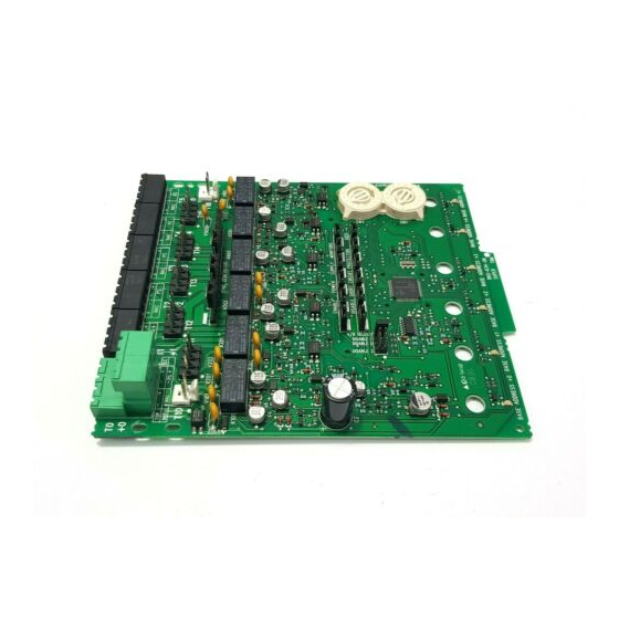
GENERAL DESCRIPTION
The XP6-C Six Circuit Supervised Control Module is intended for use in an
intelligent alarm system. Each module is intended for switching applications
involving AC, DC, or audio, which require wiring supervision. A common SLC
input is used for all modules. Each module has its own address. A pair of
rotary code switches is used to set the address of the first module from 01 to
N500-79-00
15-32 VDC
2.65 mA @ 24V
35 mA (assumes all six relays have been switched once and all six LEDs solid on)
32°F to 120°F (0°C to 49°C); –10°C to 55°C (For EN54 applications only)
10 to 93% Non-condensing
6.8"H x 5.8"W x 1.25"D
CHS-6 Chassis; BB-25 Cabinet; BB-XP Cabinet; CAB-3 Series Cabinet, CAB-4 Series Cabinet
12-18 AWG
4 VDC
50 W @ 70.7 VAC; 50 W @ 25 VAC
For class B wiring systems, 3A
For class A wiring systems, 2A
MAXIMUM VOLTAGE
25 VAC
30 VDC
30 VDC
30 VDC
70.7 VAC
125 VDC
125 VAC
125 VAC
PERMITTED IN
POSSIBLE SETTINGS
UL 864 (Y/N)
No
Enable or Disable short
circuit protection
LOAD DESCRIPTION
PF = 0.35
Resistive
Resistive
(L/R = 20ms)
PF = 0.35
Resistive
PF = 0.75
PF = 0.35
SETTINGS PERMITTED IN UL 864
Enable short circuit protection when a single power supply is
shared by multiple NACs. Short circuit protection can be disabled
only when a power supply is not shared by multiple NACs.
154. The remaining modules are automatically assigned to the next five higher
addresses. Provisions are included for disabling a maximum of three unused
modules to release the addresses to be used elsewhere. Each module also has
panel controlled green LED indicators. The panel can cause the LEDs to blink,
latch on, or latch off.
In order to synchronize strobes, horn/strobes, and speaker/strobes, a SYNC-1
accessory card (sold separately) must be used with the XP6-C. See the SYNC-1
installation manual for details on how to install.
Each module has terminals for connection to an external supply circuit for
powering devices on its NAC. Each supply must be power limited and its volt-
age/current limits must be at or below those specified. There is a short circuit
protection monitor for each module. This is provided to protect the external
power supply against short circuit conditions on the NAC.
1
12 Clintonville Road
Northford, CT 06472-1653
Phone: 203.484.7161
APPLICATION
Non-coded
Non-coded
Coded
Non-coded
Non-coded
Non-coded
Non-coded
Non-coded
I56-1805-019
Advertisement

Related Manuals for Honeywell Notifier XP6-C


Summary of Contents for Honeywell Notifier XP6-C
- Page 1 INSTALLATION AND MAINTENANCE INSTRUCTIONS XP6-C 12 Clintonville Road Six Circuit Supervised Control Module Northford, CT 06472-1653 Phone: 203.484.7161 SPECIFICATIONS Normal Operating Voltage: 15-32 VDC Stand-By Current: 2.65 mA @ 24V Alarm Current: 35 mA (assumes all six relays have been switched once and all six LEDs solid on) Temperature Range: 32°F to 120°F (0°C to 49°C);...
-
Page 2: Compatibility Requirements
INCLUDED: The front XP6-C module positions of each chassis are offset below the rear Shipped on Board: XP6-C module positions so that all of the status indicators are visible. (1) Small shunt in A/B select position Cabinets (Shipped in Class B position, remove shunt for Class A) A BB-25, CAB-3 Series or CAB-4 Series cabinet will house the CHS-6 chassis (6) Large shunts on Enable Power Supply Monitors with up to six XP6-C modules installed on it. - Page 3 Step 1: Insert the bottom of the XP6-C module down into a rear slot on the Step 3: Align two 4-40 screws with the two standoffs and tighten. chassis. Step 4: Address and wire the modules according to the instructions in this Step 2: Carefully swing the upper edge of the board back towards the back of manual.
- Page 4 NOTE: Power must not be applied to the unit when changing functionality of POWER SUPPLY WIRING AND SUPERVISION the shunts. Table 3 gives an overview of how the power connectors, T0–T5 and T10–T15, NOTE: Whether in Class B or Class A wiring, power supply monitoring and are interconnected by the circuit board (PCB).
- Page 5 FIGURE 9: EXAMPLE OF CLASS B, STYLE Y NAC CONFIGURATION WITH A SINGLE SUPPLY DEDICATED TO A SINGLE NAC. EXTERNAL POWER – SUPPLY EOLR-1 BASE ADDRESS – 6 7 8 9 – (–) (–) A/B SELECT DISABLE 1 DISABLE 2 DISABLE 3 POWER-LIMITED TOP OF T0...
- Page 6 FIGURE 11: EXAMPLE OF CLASS A, STYLE Z NAC CONFIGURATION WITH A SINGLE SUPPLY DEDICATED TO A SINGLE NAC. EXTERNAL POWER – SUPPLY EOLR-1 (TYP) (–) (–) BASE ADDRESS – 6 7 8 9 – – A/B SELECT DISABLE 1 DISABLE 2 DISABLE 3 POWER-LIMITED...
- Page 7 FIGURE 13: EXAMPLE OF CLASS B, STYLE Y AUDIO NAC CONFIGURATION. HIGH-LEVEL RETURN – 4-WIRE SUPERVISED AUDIO – AMPLIFIER (–) (–) BASE ADDRESS – 6 7 8 9 – A/B SELECT DISABLE 1 DISABLE 2 DISABLE 3 POWER-LIMITED TOP OF T0 AND SUPERVISED STATUS SLC +...
-
Page 8: Fcc Statement
FIGURE 15: EXAMPLE OF MULTIPLE BOARDS SHARING SAME EXTERNAL SUPPLY Supply is shared by NACs +0 and +1 (on PCB 1) as well as +3, +4, and +5 (on PCB 2). Refer to figures 9–12 for typical NAC wiring. Make certain lip on long power supply jumper engages retaining tab on T10 or T16 as shown in View A-A.