Advertisement
Available languages
Available languages
Quick Links
ATS1330 Power Distribution Board Installation
Sheet
EN DE
1
EN: Installation Sheet
Description
The power distribution board, model ATS1330, provides a
simple means of star connecting ATS bus devices. It is fitted
with a single protected input port and five paralleled output
ports, providing either the traditional power and comms or
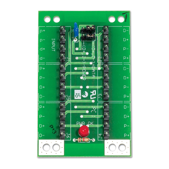
power alone. It is a standard board size and provides a power
OK LED (Figure 2, item 8) for easy diagnosis.
The module has an incoming and outgoing data bus / power
connection to achieve i.e. a proper stub connection for an
Advisor Master bus reader.
Mounting location
The ATS1330 PCB (Figure 1) can be mounted in any Advisor
Master cabinet, which supports the size B board.
Connecting the ATS1330
Figure 2
(1) ATS control panel (Mains powered device)
(2) TERM — termination link
(3) GND — earthing link
(4) Building earth
© 2019 UTC Fire & Security Americas Corporation, Inc.
2
(5) Remote arming station (RAS)
(6) Shield connection between mains powered and non-mains
powered device(s)
(7) 4-door DGP (mains powered device)
(8) Power OK LED
(9) DGP (mains powered device i.e. ATS1201)
TERM link fitted on first and last devices on the LAN. In a "star"
wiring configuration the TERM link is only fitted on the devices
at the ends of the two longest LAN cable runs.
Recommended LAN cable
WCAT52 — 2 pair twisted shielded data cable.
Note:
The shield of each length of data cable is only
connected at one end of a mains powered device with
earthing. The shield of the data cable cannot be connected at
the ATS1330. In case of a non-mains powered device, the
shield should be connected to the shield of the nearest mains
powered device (please refer to the shield connection between
device 5 and 7 in Figure 2).
Jumper settings
Input
Outputs
D+, D− = POWER
P+ (12 VDC)
P+
P− (GND)
P−
1 / 4
D+, D− = DATA
P+
P−
P/N 1077855 (ML) • REV B • ISS 12JUN19
Advertisement

Summary of Contents for Interlogix ATS1330
- Page 1 (please refer to the shield connection between The ATS1330 PCB (Figure 1) can be mounted in any Advisor device 5 and 7 in Figure 2). Master cabinet, which supports the size B board.
- Page 2 Die Abschirmung des Datenkabels kann www.interlogix.com. nicht an der ATS1330 angeschaltet werden. Wird die Platine in Geräten ohne Netzteil installiert, sollte die Abschirmung an 2012/19/EU (WEEE directive): Products marked dem nächsgelegenen Gerät mit Schutzerde angeschaltet with this symbol cannot be disposed of as unsorted municipal waste in the European Union.
- Page 3 Sie das Produkt an den gekennzeichneten Sammelstellen. Weitere Informationen hierzu finden Sie auf der folgenden Website: www.recyclethis.info Kontaktinformationen www.utcfireandsecurity.com oder www.interlogix.com Kontaktinformationen für den Kundendienst finden Sie unter www.utcfssecurityproducts.de P/N 1077855 (ML) • REV B • ISS 12JUN19 3 / 4...
- Page 4 P/N 1077855 (ML) • REV B • ISS 12JUN19 4 / 4...