Advertisement
Quick Links
Installationsanleitung
Standard MCP - Elektronikmodul
Installation Instruction
Conventional MCP - Electronic module
(Art.-Nr. / Part No. 804950 / 804951 / 804970)
Technische Änderungen vorbehalten!
798935
Technical changes reserved!
D
GB
07.2017 / AA
© 2017 Honeywell International Inc.
Novar GmbH, Dieselstraße 2, D-41469 Neuss
08
DoP-...
Novar GmbH a Honeywell Company
Dieselstraße 2, 41469 Neuss, Germany
Tel.: +49 2131 40615-600
Fax: +49 2131 40615-606
www.esser-systems.com
info@esser-systems.com
D
Bei dem Einsatz des MCP als Handfeuermelder muss zwingend
ein rotes Gehäuse und die normenkonforme Symbolik gemäß
Abb. 3/4 verwendet werden. Andere Gehäusefarben und
Beschriftungen gelten nicht als Handfeuermelder sondern als
manuelle Auslösevorrichtung.
Verdrahtungsfolge beachten!
Klemmen 1-4 IN (Eingang) OUT (Ausgang).
Fernmeldekabel I-Y (St) Y n x 2 x 0,8 mm (oder vergleichbar) mit
besonderer Kennzeichnung oder Brandmeldekabel verwenden!
Durch den Anschluss der Kabelabschirmung werden die
Signalleitungen gegen Störeinflüsse geschützt.
Anschlusskabel im Melder zum Schutz vor Feuchtigkeit mit
Abtropfschlaufe verlegen.
Bei Servicearbeiten an dem MCP eine evtl. vorhandene Alarm-
weiterleitung, wie zum Beispiel die unbeabsichtigte Auslösung
einer Alarmübertragungseinrichtung (AÜE), beachten.
Ergänzende und aktuelle Informationen
Die Produktangaben entsprechen dem Stand der Drucklegung
und können durch Produktänderungen, geänderte Normen /
Richtlinien ggf. von den hier genannten Informationen
abweichen.
Aktualisierte
Informationen,
Konformitätserklärungen
Instandhaltungsvorgaben siehe www.esser-systems.com.
esserbus
und essernet
sind in Deutschland eingetragene
®
®
Warenzeichen.
Dokumentation der Brandmelderzentrale bzgl. Normen, lokalen
Anforderungen und Systemvoraussetzungen beachten!
Handfeuermelder und automatische Brandmelder dürfen gemäß
§
den VdS-Richtlinien nicht auf einer gemeinsamen Meldergruppe
betrieben werden (max. 10 Handfeuermelder/Gruppe).
Beim Einsatz des Montagerahmens (Art.-Nr. 704967) die weiße
Abdeckplatte einsetzen.
GB
When the MCP is used as a manual call point it must be installed
in a red housing with an identification label showing the
standardize-conformal symbol as shown in Fig. 3/4. When
housings with different colours and identification labels are used
the unit is classed as a manual activation device and not as a
manual call point.
Observe the correct wiring sequence!
Terminals 1-4 IN (input) OUT (output).
Use clearly identified cable I-Y (St) Y n x 2 x 0,8 mm or
comparable and employ only shielded twisted pair cables with
special designation for fire detection, and consider furthermore
the requirements of the local standard!
The shielding must be connected for EMI protection of the cable!
Install inlaying cable with a dripping bend to protect the device from
dampness.
The alarm activation and triggering of notifying systems e.g. fire
alarm routing equipment (FARE) must be observed during any
Service of the MCP.
Additional and updated Informations
The product specification relate to the date of issue and may
differ due to modifications and/or amended Standards and
Regulations from the given informations.
For updated informations to commissioning and maintenance of
Fire alarm detectors refer to www.esser-systems.com.
esserbus
®
and essernet
®
are registered trademarks in Germany.
Observe technical manuals of the FACP to ensure compliance to
standards and local requirements of Systems features!
§
Pursuant to the VdS guidelines MCPs and automatic fire detectors
must
not
be
operated
in
a
(max. 10 MCP per detector zone).
By using the mounting frame (Part No. 704967) the white covering
must be fitted.
Achtung!
Diese Anleitung muss vor der Inbetriebnahme des Gerätes genau
durchgelesen und verstanden werden. Bei Schäden die durch Nichtbeachtung
der Installationsanleitung verursacht werden, erlischt der Gewährleistungs-
anspruch. Für Folgeschäden, die daraus resultieren, wird keine Haftung
übernommen.
Sicherheitshinweise
Den MCP NICHT an einer 230 V AC Nennspannung und nur im
vorgesehenen Temperaturbereich betreiben.
Die Wartung und Reparatur des MCP darf nur durch eine Fachkraft
erfolgen, die mit den damit verbundenen Gefahren und Vorschriften
vertraut ist.
Die Veränderung oder ein Umbau des MCP ist nicht zulässig.
Allgemein / Anwendung
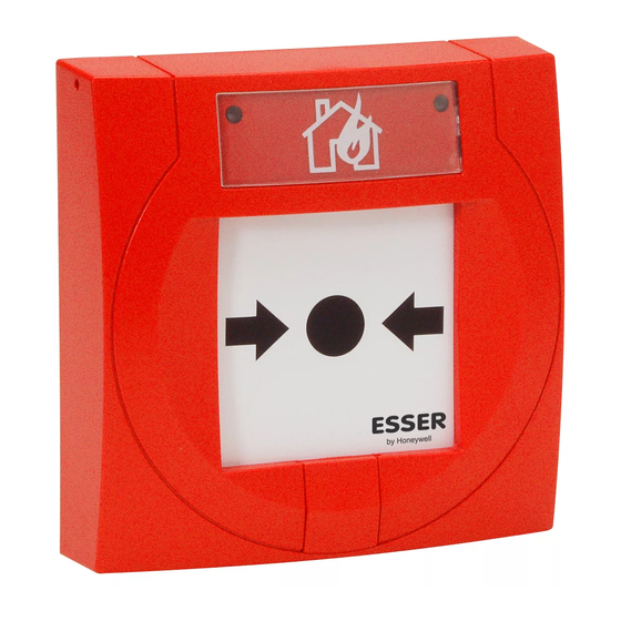
Das Standard Elektronikmodul (Art.-Nr. 804950 / 804951) bzw. der MCP
(Art.-Nr. 804970) im roten Gehäuse mit dem Symbol „brennendes Haus" wird
als Handfeuermelder zur manuellen Auslösung eines Brandalarmes bzw. einer
Gefahrenmeldung in trockenen, nicht explosionsgefährdeten Betriebsstätten
eingesetzt. Der Melder ist für andere Verwendungen auch in verschiedenen
Ausführungen, wie z. B. unterschiedlichen Gehäusefarben und verschieden
bedruckten Einlegern verfügbar (siehe Tabelle Seite 2).
Bedienung
Auslösen:
Rückstellen:
Testbetrieb:
Öffnen:
Symbolik:
Schließen:
Rückseite der
Glasscheibe oder
Papiereinleger:
Kunststoff-
bedienfeld oder
Glasscheibe:
Schutz-Kit
704965:
Montage unter Putz
Der MCP wird auf einer Standard-Schalterdose (Ø 55 – 60 mm) montiert.
Montage auf Putz
Für den optimalen IP-Schutz Kabelverschraubungen möglichst an der
Gehäuseunterseite montieren.
Erforderliche Kabeleinführungen ausschließlich an den Gehäusemarkierungen
durchbohren und jeweils mit optionalen Kabelverschraubungen M16 (bei
3 Kabeleinführungen) bzw. M20 (bei 2 Kabeleinführungen) bestücken (Abb. 8).
Kabel einführen, Kabelverschraubung festziehen, so dass keine Feuchtigkeit
o. ä. eindringen kann. Montagegehäuse auf einer glatten, geeigneten
Wandfläche, z.B. mit Dübeln (S6) und 2-4 Schrauben (Länge 40 mm)
befestigen. MCP mit beiliegenden Schrauben (3 x 30 mm, selbstschneidend)
auf dem Gehäuse montieren. Dichtungen von MCP und Montagegehäuse nicht
und
beschädigen! (Abb. 8)
Anschaltung
Die Anschaltung erfolgt über die Meldergruppe einer Brandmelderzentrale
oder an den Gruppeneingang eines esserbus
des Gehäuses abisolieren.
Die Anschaltung erfolgt über die Anschlussklemmen 1-4. Diese können zur
Vereinfachung der Installation abgezogen werden. In den letzten MCP der
Gruppe muss ein Abschlusselement (EOL) eingesetzt werden (Abb. 9).
MCP mit 2. Mikroschalter (Art.-Nr. 804951)
An den Klemmen 6/7/8 stehen potentialfreie Kontakte eines Wechslers NC/C (Öffner)
oder NO/C (Schließer) zur Verfügung (Abb. 9). Der 2. Mikroschalter wird mit dem
Auslösen des MCP aktiviert.
Kontaktbelastung: max. 30 V / 1 A
Technische Daten
Betriebsspannung
Alarmstrom
Melderzahl pro Gruppe
Alarmanzeige
Anschlussklemmen
Anwendungstemperatur
Lagertemperatur
Schutzart
Gehäuse
Farbe
Gewicht
Maße-Gehäuse (B x H x T)
Maße mit Montagegehäuse
Spezifikation
VdS-Anerkennung
common
detector
zone
Leistungserklärung
D
Scheibe mittig eindrücken bis die gelbe mechanische
Alarmanzeige (G) im oberen Fensterbereich sichtbar ist
und die rote LED (F) leuchtet (Abb. 4).
Zum
Einstecken
des
Schlüssels
die
Schlüssel-
lochabdeckung (A) hochschieben (Abb. 1).
MCP mit Glasscheibe
Gehäuse öffnen und gebrochene Glasscheibe bzw. evtl.
vorhandene Glassplitter vorsichtig entnehmen. Schlüssel (C)
bis zum Endanschlag nach rechts (L) drehen (Abb. 5). Neue
Glasscheibe
einsetzen,
MCP
schließen
und
Linksdrehung (M) des Schlüssels bis zum Endanschlag nach
oben drücken (Abb. 6).
MCP mit Kunststoffbedienfeld
Schlüssel (C) bis zum Endanschlag nach rechts (L) drehen
(Abb. 5). Kunststoffbedienfeld (K) mit einer Linksdrehung
(M) des Schlüssels bis zum Endanschlag wieder nach
oben drücken (Abb. 6).
Schlüssel (C) nach rechts (L) drehen bis sich die Scheibe
senkt und die Auslösung (F/G) angezeigt wird (Abb. 4).
Zum Rückstellen nach dem Test die Scheibe mit einer
Linksdrehung (M) des Schlüssels bis zum Endanschlag
wieder nach oben drücken.
Schlüssel mit den beiden Kunststoffzapfen in die
Öffnungen der Unterseite einstecken (Abb. 2) und
Verriegelung aufdrücken. Das Gehäuseoberteil leicht
nach oben ankippen und von dem Gehäuseunterteil
abnehmen.
Gehäuse öffnen und transparente Abdeckung (D/E) lösen
und entnehmen. Beschriftungsfeld von vorne einlegen,
ausrichten, lagerichtig mit der Abdeckung einsetzen und
andrücken (Abb. 3).
Entriegelung
mit
dem
Schlüssel
bis
zum
Endanschlag (M) drehen (Abb. 6). Gehäuseoberteil leicht
angekippt auf die oberen Vertiefungen des Unterteiles
aufsetzen und vorsichtig bis zum Einrasten zudrücken.
Zur Kennzeichnung nicht betriebsbereiter MCP (J).
Schlüssel bis zum rechten Endanschlag (L) drehen (Abb. 5).
Scheibe (H/K) lagerichtig in die Gehäusevertiefung
einlegen und durch Linksdrehung (M) des Schlüssels bis
zum Endanschlag nach oben drücken (Abb. 6).
Die Abdeckung (N) wird in die seitlichen Vertiefungen (O)
des Gehäuseoberteils eingesetzt und kann zusätzlich
verplombt (B) werden (Abb. 8).
-Kopplers. Kabel nur innerhalb
®
: 8 V DC ... 30 V DC
: ca. 9 mA @ 9 V DC
: max. 10 MCP (gemäß VdS)
: rote LED und gelbe Fahne
: max. 1,5 mm² (AWG 30-14)
: -40 °C ... +70 °C
: -40 °C ... +75 °C
: IP 43 (im Gehäuse)
: IP 55 (mit Option)
: PC/ASA Kunststoff
: rot (ähnlich RAL 3020)
: ca. 110 g
: 88 x 88 x 21 (mm)
: 88 x 88 x 54 bzw. 57 (mm)
: EN 54-11:2001 / A1:2005, Typ A
: G 205131
: DoP-20485130701 /
DoP-20486130701
GB
Important!
These instructions must be studied carefully and understood before
commissioning the device. Any damage caused by failure to observe the
installation instructions voids the warranty. Furthermore, no liability can be
accepted for any consequential damage arising from such failure.
Safety information
NEVER connect the MCP directly to a 230 V AC
operate in the specified ambient temperature range.
Only qualified technicians who are fully familiar with all the associated
hazards and the applicable legislation and regulations may perform
maintenance and repair work on the MCP.
The MCP not be changed or modified in any way.
General / Application
The conventional Electronic module (Part No. 804950 / 804951) or MCP (Part
No. 804970) in the red housing identified with a "burning house" symbol is
designated for use as a call point for manually triggering fire alarms or other
hazard alarms in dry workplaces not subject to explosion hazards. The call
point is also available in other versions for other applications, for example in
housings with different colours and with a choice of different identification labels
(refer to table – page 2)
Operation
Trigger alarm:
Press screen centre inwards until the yellow tab indicator (G)
is visible in the upper area and the red LED (F) lits (Fig. 4).
Push up the keyhole cover (A) to insert the key
(Fig. 1).
Reset:
MCP with glass screen
Open housing and carefully remove the broken glass or
possibly existing broken splinters. Turn key (C) clockwise
until the right (L) stop position (Fig. 5). Replace glass
durch
screen, close MCP and turn key anti-clockwise until the left
(M) stop position to lift screen upwards (Fig. 6).
MCP with plastic operating panel
Turn key (C) clockwise until the right (L) stop position (Fig.
5). Align the plastic operating panel (K) and turn key (M)
anti-clockwise until the left (M) stop position to lift screen
upwards (Fig. 6).
Test mode:
Turn key (C) clockwise (L) until the screen moves
downwards and the activation (F/G) are indicated (Fig. 4).
To reset the detector after a test simply turn key to the left
(M) stop position to lift screen upwards.
Opening:
Insert the key with the both tenons in the opening at the
bottom of the housing (Fig. 2) to release the cover lock.
Lift up the bottom edge of the cover a little to release it and
then remove it.
Symbolism:
Open the housing and remove the transparent plastic
cover (D/E) by prising it out. Insert the appropriate
identification label from the front. Align the cover and snap
it back into place (Fig. 3).
linken
Closing:
Turn key lock anti-clockwise until the left (M) stop position
(Fig. 6). Position the upper edge of the cover in the groove
at the top of the base and then press the cover down until
it locks into position.
Glass screen rear
side or Paper
inlay:
To indicate that the MCP is Out of Order (J).
Plastic operating
Turn key lock clockwise until the right (L) stop position (Fig. 5).
panel or
Insert screen (H/K) aligned in the front recess und move
glass screen:
screen upwards by turning the key anti-clockwise until the
left (M) stop position (Fig. 6).
Protection kit
The cover (N) is fixed by the sideway dents (O) of the
704965:
housing and may be plumbed (B) if required (Fig. 8).
Installation Flush mounting
The MCP is installed on a conventional standard housing (Ø 55 – 60 mm).
Installation Surface mounting
To ensure optimal IP protection, attach cable screw connections to the
underside of the housing, where possible.
Drill all required cable entries only at the marked housing tags and fit suitable
optional cable threads M16 (for 3 cable entries) or M20 (for 2 cable entries
Fig. 8).
Run the cable in and tighten the screw connection so that no moisture or the
like can enter. Attach the mounting box securely to a suitable wall with a smooth
surface, e.g. with 2-4 screws (length 40 mm) and dowels (S6).
Fasten the MCP to the housing with the supplied screws (3 x 30 mm self-
cutting. Do not damage rubber seals of the MCP and mounting box! (Abb. 8)
Wiring
Wiring must be carried out via the detector zone connection of the fire alarm
control panel or to the zone input of an esserbus
Only remove insulation from cable sections inside the housing.
For appropriate wiring use terminals 1-4. These terminals ma be removed to
simplify the installation. The last MCP in the zone must be fitted with an End-
Of-Line element (EOL) (Fig. 9).
nd
MCP with 2
Micro switch (Part No. 804951)
The floating contacts of a changeover relay NC/C (break) or NO/C (make) are
available on terminals 6/7/8 (Fig. 9). The 2
automatically at MCP alarm activation.
Contact rating: max. 30 V / 1 A
Specifications
Power supply
Alarm current
MCP per zone
Alarm indicator
Connection terminals
Application temperature
Storage temperature
Protection rating
Housing
Colour
Weight
Housing dimensions (w x h x d)
Dimensions with mounting box
Specification
VdS approval
Declaration of Performance
rated voltage
and only
®
transponder in a System.
nd
Micro switch is triggered
:
8 V DC ... 30 V DC
:
approx. 9 mA @ 9 V DC
:
max. 10 MCP (acc. to VdS)
:
red LED and yellow tab
:
max. 1,5 mm² (AWG 30-14)
:
-40 °C ... +70 °C
:
-40 °C ... +75 °C
:
IP 43 (in housing)
:
IP 55 (with option)
:
PC/ASA plastic
:
red (similar RAL 3020)
:
approx. 110 g
:
88 x 88 x 21 (mm)
:
88 x 88 x 54 or 57 (mm)
:
EN 54-11 :2001 / A1 :2005, type A
:
G 205131
:
DoP-20485130701 /
DoP-20486130701
Advertisement

Related Manuals for Honeywell Esser 804950


Summary of Contents for Honeywell Esser 804950
- Page 1 Schlüssel- Push up the keyhole cover (A) to insert the key 07.2017 / AA lochabdeckung (A) hochschieben (Abb. 1). (Fig. 1). © 2017 Honeywell International Inc. Rückstellen: MCP mit Glasscheibe Reset: MCP with glass screen Gehäuse öffnen und gebrochene Glasscheibe bzw. evtl.
- Page 2 Optionen Art.-Nr. Options Part No. Gehäuse für MCP, rot ähnlich RAL 3020 704950 Housing for MCP, red similar to RAL 3020 704950 Ersatzglasscheibe (10 Stück) 704960 Replacement glass screen (10 pieces) 704960 Beschriftungsfolie, transparent mit weißem Aufdruck, abweichend vom Standardpiktogramm (10 St.) 704961 Label, transparent with whit printing, differing from standard icons (10 pieces) 704961...