Table of Contents
Advertisement
Quick Links
Advertisement
Table of Contents

Related Manuals for Texas Instruments DS90UH949A-Q1EVM


Summary of Contents for Texas Instruments DS90UH949A-Q1EVM
- Page 1 DS90UH949A-Q1EVM User's Guide Literature Number: SNLU232 August 2018...
-
Page 2: Table Of Contents
................1.13 Typical Connection and Test Equipment ....................1.14 Equipment References ......................1.15 Cable References ........................Bill of Materials ......................EVM PCB Schematics ........................Board Layout Contents SNLU232 – August 2018 Submit Documentation Feedback Copyright © 2018, Texas Instruments Incorporated... - Page 3 Board Layer - Power Split/GND ....................B-7. Board Layer - Ground - 2 ...................... B-8. Board Layer - Bottom ..................... B-9. Board Layer - Bottom Solder SNLU232 – August 2018 List of Figures Submit Documentation Feedback Copyright © 2018, Texas Instruments Incorporated...
- Page 4 1-12. Configuration Select (MODE_SEL0) -- SW-DIP8 - S2 ..............1-13. Configuration Select (MODE_SEL1) - SW-DIP8 - S6 ......................1-14. IDx SW-DIP8 - S3 ......................2-1. Bill of Materials List of Tables SNLU232 – August 2018 Submit Documentation Feedback Copyright © 2018, Texas Instruments Incorporated...
-
Page 5: Ds90Uh949A-Q1Evm User's Guide
DS90UH949A-Q1EVM User's Guide General Description The DS90UH949A-Q1EVM (Evaluation Module) converts HDMI to FPD-Link III. This kit will demonstrate the functionality and operation of the DS90UH949A-Q1. The DS90UH949A-Q1 is an HDMI to FPD-Link III Serializer which, in conjunction with the DS90UH940-Q1/DS90UH948-Q1 Deserializers, takes the data from HDMI serial stream and translates it into either single- or dual-lane FPD-Link III interface. -
Page 6: System Requirements
Deserializer D4+/- D5+/- D6+/- D7+/- D_GPIO D_GPIO (SPI) (SPI) HDCP ± High-Bandwidth Content Protection HDMI ± High Definition Multimedia Interface Figure 1-1. Applications Diagram DS90UH949A-Q1EVM User's Guide SNLU232 – August 2018 Submit Documentation Feedback Copyright © 2018, Texas Instruments Incorporated... -
Page 7: Typical Configuration
5. Connect J34 with the miniUSB cable to PC USB port (5-pin_ to USB A (4-pin)) For details of pin-names and pin-functions, see the DS90UH949A-Q1 datasheet. SNLU232 – August 2018 DS90UH949A-Q1EVM User's Guide Submit Documentation Feedback Copyright © 2018, Texas Instruments Incorporated... -
Page 8: Interfacing To The Evm
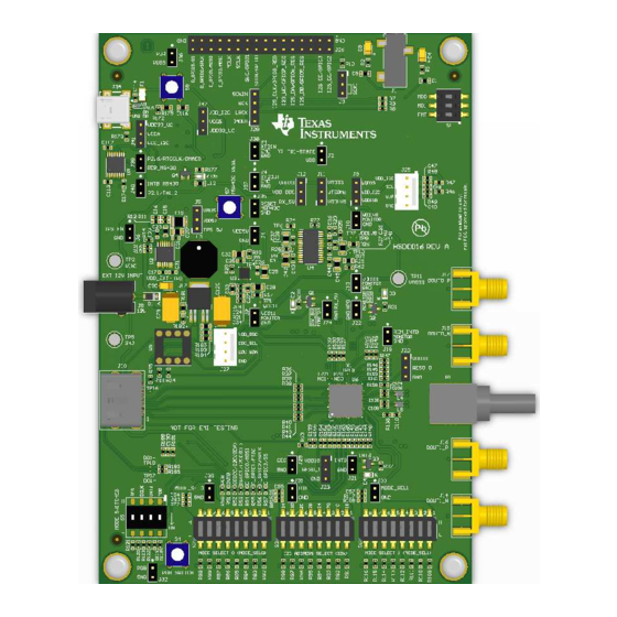
DOUT0+ EXTERNAL 12V HERE VDD_DDC DDC_SCL DOUT0- DDC_SDA APPLY HDMI DS90UH949A INPUT HERE DOUT1+ DOUT1- MODE_SEL0 MODE_SEL1 MOMENTARY Figure 1-3. Interfacing to the EVM DS90UH949A-Q1EVM User's Guide SNLU232 – August 2018 Submit Documentation Feedback Copyright © 2018, Texas Instruments Incorporated... -
Page 9: Default Jumper Settings
1 ON (silk screen L side), 2-8 OFF (silk screen H side) 1-2 OFF (silk screen H side), 3-4 ON (silk screen L side) SNLU232 – August 2018 DS90UH949A-Q1EVM User's Guide Submit Documentation Feedback Copyright © 2018, Texas Instruments Incorporated... -
Page 10: Demo Board Connections
IN_D2+ Table 1-7. USB2ANY Connector Designator Description mini USB 5 pin Table 1-8. I2C/CCI Interface Header J25 Designator Signal J25.1 VDDI2C J25.2 J25.3 J25.4 DS90UH949A-Q1EVM User's Guide SNLU232 – August 2018 Submit Documentation Feedback Copyright © 2018, Texas Instruments Incorporated... -
Page 11: Gpio/Audio Interface
If available, remote EDID is copied into internal SRAM EDID. Table 1-12. Configuration Select (MODE_SEL0) -- SW-DIP8 - S2 MODE # EDID_SEL AUX_I2S Only set one high. SNLU232 – August 2018 DS90UH949A-Q1EVM User's Guide Submit Documentation Feedback Copyright © 2018, Texas Instruments Incorporated... -
Page 12: Configuration Select (Mode_Sel1) - Sw-Dip8 - S6
0x0E 0x1C S3.3 0x10 0x20 S3.4 0x12 0x24 S3.5 0x14 0x28 S3.6 0x16 0x2C S3.7 0x18 0x30 S3.8 0x1A 0x34 Only set one high. DS90UH949A-Q1EVM User's Guide SNLU232 – August 2018 Submit Documentation Feedback Copyright © 2018, Texas Instruments Incorporated... -
Page 13: Alp Software Setup
“Launch Analog LaunchPAD” is checked, but it will not be useful until the USB driver is installed and board is attached. Connect the J34 USB jack of the DS90UH949A-Q1EVM board to a PC or laptop USB port using a Type A MINI... -
Page 14: Launching Alp
Under the Devices tab, click on “DS90Ux949” to select the device and open up the device profile with its associated tabs. Figure 1-5. Initial ALP Screen DS90UH949A-Q1EVM User's Guide SNLU232 – August 2018 Submit Documentation Feedback Copyright © 2018, Texas Instruments Incorporated... -
Page 15: Follow-Up Screen
ALP Software Setup www.ti.com After selecting the DS90Ux949, the screen shown in Figure 1-6 should appear. Figure 1-6. Follow-Up Screen SNLU232 – August 2018 DS90UH949A-Q1EVM User's Guide Submit Documentation Feedback Copyright © 2018, Texas Instruments Incorporated... -
Page 16: Information Tab
1.11.5 Information Tab The Information tab is shown in Figure 1-7. Note the device revision could be different. Figure 1-7. ALP Information Tab DS90UH949A-Q1EVM User's Guide SNLU232 – August 2018 Submit Documentation Feedback Copyright © 2018, Texas Instruments Incorporated... -
Page 17: Hdmi Tab
ALP Software Setup www.ti.com 1.11.6 HDMI Tab The HDMI tab is shown in Figure 1-8. Figure 1-8. ALP HDMI Tab SNLU232 – August 2018 DS90UH949A-Q1EVM User's Guide Submit Documentation Feedback Copyright © 2018, Texas Instruments Incorporated... -
Page 18: Pattern Generator Tab
ALP Software Setup www.ti.com 1.11.7 Pattern Generator Tab The SER Pattern Generator tab is shown in Figure 1-9. Figure 1-9. ALP Pattern Generator Tab DS90UH949A-Q1EVM User's Guide SNLU232 – August 2018 Submit Documentation Feedback Copyright © 2018, Texas Instruments Incorporated... -
Page 19: Registers Tab
ALP Software Setup www.ti.com 1.11.8 Registers Tab The Registers tab is shown in Figure 1-10. Figure 1-10. ALP Registers Tab SNLU232 – August 2018 DS90UH949A-Q1EVM User's Guide Submit Documentation Feedback Copyright © 2018, Texas Instruments Incorporated... -
Page 20: Registers Tab - Address 0X00 Selected
Address 0x00 selected as shown in Figure 1-11. Note that the “Value:” box, , will now show the hex value of that register. Figure 1-11. ALP Device ID Selected DS90UH949A-Q1EVM User's Guide SNLU232 – August 2018 Submit Documentation Feedback Copyright © 2018, Texas Instruments Incorporated... -
Page 21: Registers Tab - Address 0X00 Expanded
Click the “Apply” button to write to the register, and “refresh” to see the new value of the selected (highlighted) register. The box toggles on every mouse click. SNLU232 – August 2018 DS90UH949A-Q1EVM User's Guide Submit Documentation Feedback Copyright © 2018, Texas Instruments Incorporated... -
Page 22: Scripting Tab
ALP Framework application. DS90UH949A-Q1EVM User's Guide SNLU232 – August 2018 Submit Documentation Feedback Copyright © 2018, Texas Instruments Incorporated... -
Page 23: Troubleshooting Alp Software
Highlight the incorrect profile in the Defined ALP Devices list and click the remove button. Figure 1-15. Remove Incorrect Profile Find the correct profile under the Select a Daughter Board list, highlight the profile, and click Add. SNLU232 – August 2018 DS90UH949A-Q1EVM User's Guide Submit Documentation Feedback Copyright © 2018, Texas Instruments Incorporated... -
Page 24: Add Correct Profile
Troubleshooting ALP Software www.ti.com Figure 1-16. Add Correct Profile Click Ok and the correct profile should load. Figure 1-17. Finish Setup DS90UH949A-Q1EVM User's Guide SNLU232 – August 2018 Submit Documentation Feedback Copyright © 2018, Texas Instruments Incorporated... -
Page 25: Alp Does Not Detect The Evm
Check the device manager to make sure that the USB driver is installed. There should be a “HID- compliant device” under the “Human Interface Devices” as shown in Figure 1-19. Figure 1-19. Windows 7, ALP USB Driver SNLU232 – August 2018 DS90UH949A-Q1EVM User's Guide Submit Documentation Feedback Copyright © 2018, Texas Instruments Incorporated... -
Page 26: Alp In Demo Mode
After demo mode is disabled, the ALP software will poll the ALP hardware. The ALP software will update and have only “DS90UH949” under the “Devices” drop-down menu. DS90UH949A-Q1EVM User's Guide SNLU232 – August 2018 Submit Documentation Feedback Copyright © 2018, Texas Instruments Incorporated... -
Page 27: Typical Connection And Test Equipment
DIGITAL VIDEO GENERATOR VIDEO GENERATOR OpenLDI FPD-Link III Digital Video Source Logic Analyzer / Oscilloscope Contents of Demo Kit Figure 1-23. Typical Test Setup for Evaluation SNLU232 – August 2018 DS90UH949A-Q1EVM User's Guide Submit Documentation Feedback Copyright © 2018, Texas Instruments Incorporated... -
Page 28: Equipment References
For optimal performance, TI recommends a Shielded Twisted-Pair (STP), 24 AWG (or larger diameter) cable with a 100-Ω differential impedance for high-speed data applications. Leoni Dacar 538 series cable: www.leoni-automotive-cables.com Rosenberger HSD connector: www.rosenberger.de/en/Products/35_Automotive_HSD.php DS90UH949A-Q1EVM User's Guide SNLU232 – August 2018 Submit Documentation Feedback Copyright © 2018, Texas Instruments Incorporated... -
Page 29: Bill Of Materials
CAP, TA, 2.2 µF, 3216-18 293D225X9025A Vishay-Sprague 25 V, +/- 10%, 2TE3 6.3 ohm, SMD 0.01uF CAP, CERM, 0603 06031C103JAT2 0.01 µF, 100 V,+/- 5%, X7R, 0603 SNLU232 – August 2018 Bill of Materials Submit Documentation Feedback Copyright © 2018, Texas Instruments Incorporated... - Page 30 H3, H4, H7, H8 Machine Screw, Screw NY PMS 440 B and F Round, #4-40 x 0025 PH Fastener Supply 1/4, Nylon, Philips panhead Bill of Materials SNLU232 – August 2018 Submit Documentation Feedback Copyright © 2018, Texas Instruments Incorporated...
- Page 31 RES, 22.1 k, 1%, 0402 CRCW040222K1 Vishay-Dale 0.063 W, 0402 FKED R13, R17, R26, RES, 0, 5%, 0.1 0603 CRCW06030000 Vishay-Dale W, 0603 Z0EA SNLU232 – August 2018 Bill of Materials Submit Documentation Feedback Copyright © 2018, Texas Instruments Incorporated...
- Page 32 Vishay-Dale 0.063 W, 0402 FKED R68, R77, R104 82.5k RES, 82.5 k, 1%, 0402 CRCW040282K5 Vishay-Dale 0.063 W, AEC- FKED Q200 Grade 0, 0402 Bill of Materials SNLU232 – August 2018 Submit Documentation Feedback Copyright © 2018, Texas Instruments Incorporated...
- Page 33 TP2, TP5, TP11 Terminal, Turret, Keystone1502-2 1502-2 Keystone TH, Double 4.5V to 18V PWP0014E TPS54225PWP Texas Input, 2A Instruments Synchronous Step-Down Converter, PWP0014E (TSSOP-14) SNLU232 – August 2018 Bill of Materials Submit Documentation Feedback Copyright © 2018, Texas Instruments Incorporated...
- Page 34 Sb/Br) 16-Bit Ultra-Low- PN0080A MSP430F5529IP Texas Power Instruments Microcontroller, 128KB Flash, 8KB RAM, USB, 12Bit ADC, 2 USCIs, 32Bit HW MPY, PN0080A (LQFP-80) Bill of Materials SNLU232 – August 2018 Submit Documentation Feedback Copyright © 2018, Texas Instruments Incorporated...
- Page 35 Ferrite Bead, 0402 BLM15AX102SN MuRata 1000 ohm @ 100 MHz, 0.35 A, 0402 R1, R2 RES, 100, 1%, 0402 CRCW0402100 Vishay-Dale 0.063 W, 0402 RFKED SNLU232 – August 2018 Bill of Materials Submit Documentation Feedback Copyright © 2018, Texas Instruments Incorporated...
- Page 36 V Input, 5-pin PFM (KVU), -40 to 125 degC, Green (RoHS and no Sb/Br) OSC, 12.288 14x9.8x4.7mm ECS-8FA3X- ECS Inc. MHz, 3.3 Vdc, 122.8-TR Bill of Materials SNLU232 – August 2018 Submit Documentation Feedback Copyright © 2018, Texas Instruments Incorporated...
- Page 37 Reference OSC, 96 MHz, SMD, 4-Leads, FXO-HC736R-96 Fox Electronics 3.3 Vdc, SMD Body 7x5mm OSC, 148.5 7x5mm FVXO-LC73BR- MHz, LVDS, 3.3 148.5 V, SMD SNLU232 – August 2018 Bill of Materials Submit Documentation Feedback Copyright © 2018, Texas Instruments Incorporated...
-
Page 38: Evm Pcb Schematics
Appendix A SNLU232 – August 2018 EVM PCB Schematics Figure A-1. Schematic - Block Diagram EVM PCB Schematics SNLU232 – August 2018 Submit Documentation Feedback Copyright © 2018, Texas Instruments Incorporated... -
Page 39: Schematic - Ds90Uh949A-Q1 And Power Decoupling
Appendix A www.ti.com Figure A-2. Schematic - DS90UH949A-Q1 and Power Decoupling SNLU232 – August 2018 EVM PCB Schematics Submit Documentation Feedback Copyright © 2018, Texas Instruments Incorporated... -
Page 40: Schematic - Msp430
Appendix A www.ti.com Figure A-3. Schematic - MSP430 EVM PCB Schematics SNLU232 – August 2018 Submit Documentation Feedback Copyright © 2018, Texas Instruments Incorporated... - Page 41 Appendix A www.ti.com Figure A-4. Schematic - PDB, IDx and MODE_SEL Switches SNLU232 – August 2018 EVM PCB Schematics Submit Documentation Feedback Copyright © 2018, Texas Instruments Incorporated...
-
Page 42: Schematic - Hdmi, Hsd, Sma, I2C, Ddc, Cec And Gpio/I2S/Spi Connectors
Appendix A www.ti.com Figure A-5. Schematic - HDMI, HSD, SMA, I2C, DDC, CEC and GPIO/I2S/SPI Connectors EVM PCB Schematics SNLU232 – August 2018 Submit Documentation Feedback Copyright © 2018, Texas Instruments Incorporated... -
Page 43: Schematic - Leds
Appendix A www.ti.com Figure A-6. Schematic - LEDs SNLU232 – August 2018 EVM PCB Schematics Submit Documentation Feedback Copyright © 2018, Texas Instruments Incorporated... -
Page 44: Schematic - Audio (Not Populated)
Appendix A www.ti.com Figure A-7. Schematic - Audio (Not Populated) EVM PCB Schematics SNLU232 – August 2018 Submit Documentation Feedback Copyright © 2018, Texas Instruments Incorporated... -
Page 45: Schematic - Power Regulators
Appendix A www.ti.com Figure A-8. Schematic - Power Regulators SNLU232 – August 2018 EVM PCB Schematics Submit Documentation Feedback Copyright © 2018, Texas Instruments Incorporated... -
Page 46: Schematic - Hardware
Appendix A www.ti.com Figure A-9. Schematic - Hardware EVM PCB Schematics SNLU232 – August 2018 Submit Documentation Feedback Copyright © 2018, Texas Instruments Incorporated... -
Page 47: Board Layout
Appendix B SNLU232 – August 2018 Board Layout Board Layers Figure B-1. Board Layer - Top Overlay SNLU232 – August 2018 Board Layout Submit Documentation Feedback Copyright © 2018, Texas Instruments Incorporated... -
Page 48: Board Layer - Top Solder
Appendix B www.ti.com Figure B-2. Board Layer - Top Solder Board Layout SNLU232 – August 2018 Submit Documentation Feedback Copyright © 2018, Texas Instruments Incorporated... -
Page 49: Board Layer - Top
Appendix B www.ti.com Figure B-3. Board Layer - Top SNLU232 – August 2018 Board Layout Submit Documentation Feedback Copyright © 2018, Texas Instruments Incorporated... -
Page 50: Board Layer - Ground-1
Appendix B www.ti.com Figure B-4. Board Layer - Ground-1 Board Layout SNLU232 – August 2018 Submit Documentation Feedback Copyright © 2018, Texas Instruments Incorporated... -
Page 51: Board Layer - Signal Layer
Appendix B www.ti.com Figure B-5. Board Layer - Signal Layer SNLU232 – August 2018 Board Layout Submit Documentation Feedback Copyright © 2018, Texas Instruments Incorporated... -
Page 52: Board Layer - Power Split/Gnd
Appendix B www.ti.com Figure B-6. Board Layer - Power Split/GND Board Layout SNLU232 – August 2018 Submit Documentation Feedback Copyright © 2018, Texas Instruments Incorporated... -
Page 53: Board Layer - Ground
Appendix B www.ti.com Figure B-7. Board Layer - Ground - 2 SNLU232 – August 2018 Board Layout Submit Documentation Feedback Copyright © 2018, Texas Instruments Incorporated... -
Page 54: Board Layer - Bottom
Appendix B www.ti.com Figure B-8. Board Layer - Bottom Board Layout SNLU232 – August 2018 Submit Documentation Feedback Copyright © 2018, Texas Instruments Incorporated... -
Page 55: Board Layer - Bottom Solder
Appendix B www.ti.com Figure B-9. Board Layer - Bottom Solder SNLU232 – August 2018 Board Layout Submit Documentation Feedback Copyright © 2018, Texas Instruments Incorporated... - Page 56 IMPORTANT NOTICE FOR TI DESIGN INFORMATION AND RESOURCES Texas Instruments Incorporated (‘TI”) technical, application or other design advice, services or information, including, but not limited to, reference designs and materials relating to evaluation modules, (collectively, “TI Resources”) are intended to assist designers who are developing applications that incorporate TI products;...
- Page 57 Mouser Electronics Authorized Distributor Click to View Pricing, Inventory, Delivery & Lifecycle Information: Texas Instruments DS90UH949A-Q1EVM DS90UB949A-Q1EVM...