Table of Contents
Advertisement
GETTING STARTED GUIDE
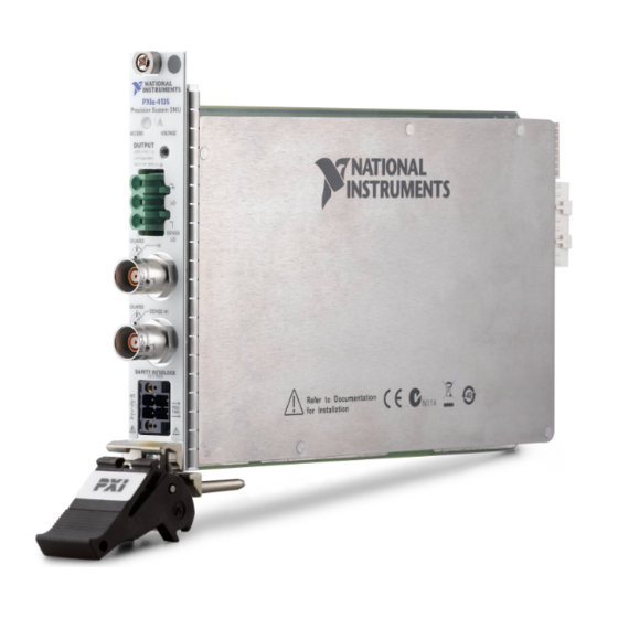
PXIe-4135
Single-Channel Precision System Source Measure Unit (SMU)
Note
Before you begin, install and configure your chassis and controller.
This document explains how to install, configure, and test the PXIe-4135. The PXIe-4135 is a
single-channel precision system SMU.
To access PXIe-4135 documentation, navigate to Start»All Programs»National
Instruments»NI-DCPower»Documentation.
Caution
Product misuse can result in a hazard. You can compromise the safety protection
built into the product if the product is damaged in any way. If the product is
damaged, return it to NI for repair.
Contents
Electromagnetic Compatibility Guidelines............................................................................... 2
Safety Guidelines for Hazardous Voltages................................................................................2
Verifying the System Requirements..........................................................................................2
Unpacking the Kit..................................................................................................................... 3
Kit Contents.............................................................................................................................. 4
Other Equipment............................................................................................................... 4
Preparing the Environment....................................................................................................... 5
Installing the Software.............................................................................................................. 5
Safety........................................................................................................................................ 6
System Safety Guidelines......................................................................................................... 6
Safety Guidelines for System Design and Implementation.............................................. 6
Safety Guidelines for System Operation...........................................................................7
Installing the PXIe-4135........................................................................................................... 8
PXIe-4135 Front Panel............................................................................................................11
Accessories..............................................................................................................................12
Configuring the PXIe-4135 in MAX...................................................................................... 12
Testing the Safety Interlock.................................................................................................... 13
Testing with an Application Development Environment................................................13
Testing with the NI-DCPower Soft Front Panel............................................................. 13
Programming the PXIe-4135.................................................................................................. 15
Troubleshooting...................................................................................................................... 15
What Should I Do if the PXIe-4135 Doesn't Appear in MAX?......................................15
Why Is the ACCESS LED Off When the Chassis Is On?...............................................16
Do not operate the PXIe-4135 in a manner not specified in this document.
Advertisement
Table of Contents

Related Manuals for National Instruments PXIe-4135


Summary of Contents for National Instruments PXIe-4135
-
Page 1: Table Of Contents
Single-Channel Precision System Source Measure Unit (SMU) Note Before you begin, install and configure your chassis and controller. This document explains how to install, configure, and test the PXIe-4135. The PXIe-4135 is a single-channel precision system SMU. To access PXIe-4135 documentation, navigate to Start»All Programs»National Instruments»NI-DCPower»Documentation. -
Page 2: Electromagnetic Compatibility Guidelines
When operating channels in series or floating on top of external voltage references, ensure that no terminal exceeds this rating. Verifying the System Requirements To use the NI-DCPower instrument driver, your system must meet certain requirements. 2 | ni.com | PXIe-4135 Getting Started Guide... -
Page 3: Unpacking The Kit
Do not install a device if it appears damaged in any way. Unpack any other items and documentation from the kit. Store the device in the antistatic package when the device is not in use. PXIe-4135 Getting Started Guide | © National Instruments | 3... -
Page 4: Kit Contents
3. Safety Interlock Input Connector Other Equipment There are several required items not included in your device kit that you need to operate the PXIe-4135. Your application may require additional items not included in your kit to install or operate your device. Required Items •... -
Page 5: Preparing The Environment
Preparing the Environment Ensure that the environment you are using the PXIe-4135 in meets the following specifications. Operating Environment Ambient temperature range 0 °C to 55 °C (Tested in accordance with IEC 60068-2-1 and IEC 60068-2-2. Meets MIL-PRF-28800F Class 3 low temperature limit and MIL-PRF-28800F Class 2 high temperature limit.) -
Page 6: Safety
Refer to IEC 61010-1 for specific insulation requirements. Safety Interlock System Integration The PXIe-4135 includes a safety interlock circuit that places the outputs of the SMU in a safe state, regardless of the programmed state of the module. •... -
Page 7: Safety Guidelines For System Operation
Safety Guidelines for System Operation Caution Hazardous voltages of up to the maximum voltage of the PXIe-4135 may appear at the output terminals if the safety interlock terminal is closed. Open the safety interlock terminal when the output connections are accessible. With the safety interlock terminal open, the output voltage level/limit is limited to ±40 V DC, and... -
Page 8: Installing The Pxie-4135
Do not apply voltage to the safety interlock connector inputs. The interlock connector is designed to accept passive, normally open contact closure connections only. To ensure a system containing the PXIe-4135 is safe for operators, components, or conductors, take the following safety precautions: •... - Page 9 LO and sense LO cables beyond the body of the connector. Clamp down using the screw terminals on the connector. Verify that no exposed shield foil or braid extends outside of the backshell. PXIe-4135 Getting Started Guide | © National Instruments | 9...
- Page 10 Connect the safety interlock connector to the device. 15. Power on the chassis. 16. Perform the safety interlock test. Related Information Testing the Safety Interlock on page 13 10 | ni.com | PXIe-4135 Getting Started Guide...
-
Page 11: Pxie-4135 Front Panel
Precision System SMU ACCESS VOLTAGE OUTPUT ±200 V , 1 A, 3 A Pulse MAX 250 V MAX to SENSE GUARD GUARD SENSE HI SAFETY INTERLOCK 3.3 V MAX INT. PASS- THRU PXIe-4135 Getting Started Guide | © National Instruments | 11... -
Page 12: Accessories
NI hardware products are in the system and how they are configured. MAX is automatically installed with NI-DCPower. Launch MAX. In the configuration tree, expand Devices and Interfaces to see the list of installed NI hardware. 12 | ni.com | PXIe-4135 Getting Started Guide... -
Page 13: Testing The Safety Interlock
The MAX self-test performs a basic verification of hardware resources. Testing the Safety Interlock To ensure safe operation of the PXIe-4135, periodically test the safety interlock for proper functionality. The recommended test interval is at least once per day of continuous usage. - Page 14 10. Verify that the Voltage Status Indicator is red and that a hazardous voltage error message appears. 11. On the error message dialog, click OK to prompt the PXIe-4135 to attempt to clear the error and re-initialize the session to default values.
-
Page 15: Programming The Pxie-4135
Troubleshooting If an issue persists after you complete a troubleshooting procedure, contact NI technical support or visit ni.com/support. What Should I Do if the PXIe-4135 Doesn't Appear in MAX? In the MAX configuration tree, expand Devices and Interfaces. Expand the Chassis tree to see the list of installed hardware, and press <F5> to refresh the list. -
Page 16: Why Is The Access Led Off When The Chassis Is On
Windows 7 Select Start»Control Panel»Device Manager. If you are using a PXI or PXI Express controller, verify that a National Instruments entry appears in the System Devices list. Reinstall NI-DCPower and the module if error conditions appear in the list. If you are using an MXI controller, right-click PCI-to-PCI Bridge, and select Properties from the shortcut menu to verify that the bridge is enabled. - Page 17 (EMC) and product safety. You can obtain the DoC for your product by visiting ni.com/certification. If your product supports calibration, you can obtain the calibration certificate for your product at ni.com/calibration. PXIe-4135 Getting Started Guide | © National Instruments | 17...
- Page 18 CONTAINED HEREIN AND SHALL NOT BE LIABLE FOR ANY ERRORS. U.S. Government Customers: The data contained in this manual was developed at private expense and is subject to the applicable limited rights and restricted data rights as set forth in FAR 52.227-14, DFAR 252.227-7014, and DFAR 252.227-7015. © 2016 National Instruments. All rights reserved. 374873B-01 Aug16...