Table of Contents
Advertisement
Quick Links
Instructions - Parts
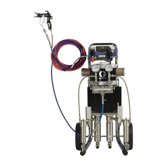
M2K Spray Packages
For two-component finishing and coating applications in hazardous and non-hazardous
locations. For professional use only.
Important Safety Instructions
Read all warnings and instructions in this manual.
Save these instructions.
See page 4 for Model Information.
See page 53 for Maximum Working Pressure.
Cart Mount
Wall Mount
II 2 G
333309K
EN
Ex h IIB T3 Gb
Advertisement
Table of Contents

Related Manuals for Graco M2K


Summary of Contents for Graco M2K
- Page 1 Instructions - Parts M2K Spray Packages 333309K For two-component finishing and coating applications in hazardous and non-hazardous locations. For professional use only. Important Safety Instructions Read all warnings and instructions in this manual. Save these instructions. See page 4 for Model Information.
-
Page 2: Table Of Contents
Air Line Accessories ..... 14 Graco Standard Warranty ....54 Flush Kits . -
Page 3: Related Manuals
Related Manuals Related Manuals Manual Description 333309 M2K Spray Packages 334625 M2K Mix Manifolds 3A0732 ® Merkur ES Spray Packages 308652 ™ Husky 205 Air-Operated Diaphragm Pumps 312796 ® Air Motor 312792 ® Merkur Displacement Pump 307273 Fluid Outlet Filter... -
Page 4: Models
Models Models Sprayer Pump Mounting Fluid Filters and Type Ratio Type Model Fluid/Air Hose Lower A Lower B Motor Cart 24V868 1/4 ID Mix Fluid Hose x 25 ft. (7.6 m) 50cc 50cc Wall 24V874 None Cart 24V869 1/4 ID Mix Fluid Hose x 25 ft. (7.6 m) 100cc 50cc Wall... -
Page 5: Warnings
Warnings Warnings The following warnings are for the setup, use, grounding, maintenance, and repair of this equipment. The exclama- tion point symbol alerts you to a general warning and the hazard symbols refer to procedure-specific risks. When these symbols appear in the body of this manual, refer back to these Warnings. Additional, product-specific warnings may be found throughout the body of this manual where applicable. - Page 6 Warnings WARNING WARNING WARNING WARNING EQUIPMENT MISUSE HAZARD Misuse can cause death or serious injury. • Do not operate the unit when fatigued or under the influence of drugs or alcohol. • Do not exceed the maximum working pressure or temperature rating of the lowest rated system com- ponent.
-
Page 7: Important Isocyanate (Iso) Information
Important Isocyanate (ISO) Information Important Isocyanate (ISO) Information Isocyanates (ISO) are catalysts used in two component materials. Isocyanate Conditions NOTICE Partially cured ISO will reduce performance and the life of all wetted parts. Spraying or dispensing materials containing isocya- • Always use a sealed container with a desiccant nates creates potentially harmful mists, vapors, and dryer in the vent, or a nitrogen atmosphere. -
Page 8: Introduction
Introduction Introduction Typical System Installation The Graco M2K spray packages are intended for use with two-component epoxy, polyurethane, and polyester split batch (Model 24W609) materials in industrial appli- . 1 is only a guide for selecting and installing system cations. When maintained and operated properly they components and accessories. -
Page 9: Notes
Introduction Notes 333309K... -
Page 10: Proportioner Overview
Introduction Proportioner Overview B Supply A Supply . 2 Typical Installation, Non-Polyester Models 333309K... - Page 11 Introduction Air Shutoff Valve (optional accessory, purchase separately) - Isolates the air line accessories for servicing. Air Filter (optional accessory, purchase separately) - Removes harmful dirt and moisture from the com- pressed air supply. Gun Air Pressure Gauge - Displays atomizing air pressure to spray gun. Gun Air Pressure Regulator - Adjusts the air pressure to the air spray or air-assisted spray gun (L).
-
Page 12: Model 24W609 (For Polyester Applications)
Introduction Model 24W609 (for Polyester applications) B Supply A Supply . 3 Typical Installation, Polyester Model 333309K... - Page 13 Introduction Air Shutoff Valve (optional accessory, purchase separately) - Isolates the air line accessories for servicing. Air Filter (optional accessory, purchase separately) - Removes harmful dirt and moisture from the com- pressed air supply. Gun Air Pressure Gauge - Displays atomizing air pressure to spray gun. Used only if the application requires an optional air spray or air-assisted spray gun (sold separately).
-
Page 14: Installation
Installation Installation Prepare the Operator Wall Mount Packages All persons who operate the equipment must be trained Before installing a wall mounted package, ensure the in the operation of all system components as well as the wall can support the weight of the pump, bracket, hoses proper handling of all fluids. -
Page 15: Grounding
Installation Grounding 3. Air compressor Follow manufacturer's recommendations. 4. Spray gun The equipment must be grounded to reduce the risk Ground through connection to a properly grounded of static sparking. Static sparking can cause fumes to fluid hose and pump. ignite or explode. -
Page 16: Setup
1. Attach fittings to the air control module. exceeded. 2. Attach the air hose to the fitting on the air control Review your feed systems with your Graco Distributor. module. NOTE: The air supply line to proportioner module has to be a minimum of 3/8 in. -
Page 17: A And B Components
(13 mm) long steel tube, coupled to the fluid supply hoses. A needle-type flow control valve could also be Be aware that when facing the manifold on the propor- used. Contact your Graco distributor for assistance in tioner: selecting the proper type of flow restrictor for your appli- •... -
Page 18: Flush The Pump Before First Use
(Q) using a Phillips head screwdriver. 9. Connect the fluid hoses back to the mix manifold inlet. 2. Fill the wet cup (T) one-half full with Graco Throat NOTICE Seal Liquid (TSL) or compatible solvent. ISO oil may be used on the “B” side of the proportioner. -
Page 19: Operation
Operation Operation Pressure Relief Procedure 7. If you suspect that pressure has not been fully relieved after following the steps above, check the following: Follow the Pressure Relief Procedure whenever you see this symbol. a. The spray tip may be completely clogged. Very slowly loosen the air cap retaining ring to relieve pressure in the cavity between the ball/seat shutoff and the plugged tip. -
Page 20: Prime The Pump
Operation Prime the Pump 9. Standard Procedure: Reattach A and B pump out- let hoses (CC) to fluid pressure gauges (PA, PB) on the mix manifold (F). Procedure for Polyester Model 24W609: Close the return valves on both A and B pump outlets. To avoid injury and equipment damage from NOTE: For Polyester Model 24W609, continue with over-pressurization, always use the minimum air... - Page 21 Operation 2. Verify solvent valves (S) on the mix manifold (F) are 7. Allow pumps to run until mixed material is flowing closed (both A and B sides). Move mix manifold from the front of the gun then release the gun trig- handle to the mix position.
-
Page 22: Spray Gun Adjustment
Operation Spray Gun Adjustment Adjust the Spray Pattern Packages with Airless Guns For AA Spray Guns The spray tip orifice and spray angle determine pattern Adjust the Atomization coverage and size. When you need more coverage, use a larger spray tip rather than increasing fluid pressure. Align guard horizontally to spray a horizontal pattern. -
Page 23: Mix Material Flush Procedure
Operation Mix Material Flush Procedure 4. Engage the gun trigger lock. 5. Remove the spray tip and/or air cap. Standard procedure for all pumps except polyester model 24W609 To avoid fire and explosion, always ground equipment and waste container. To avoid static sparking and injury from splashing, always flush at lowest possible pressure. - Page 24 Operation 9. Trigger gun for 3 seconds into a grounded metal pail, until the mixed fluid is purged from the system waste pail holding a metal part of gun firmly to the and clean solvent is flowing. pail. 13. Close A side solvent flush valve. 10.
- Page 25 Operation 15. Trigger gun for 3 seconds into a grounded metal 18. Turn off air regulator to solvent pump. Close the waste pail holding a metal part of gun firmly to the bleed type air supply valve to the solvent pump. pail.
-
Page 26: Using The Proportioning Pump System
Operation 8. Turn off the solvent supply pump. Using the Proportioning Pump System 9. Trigger the gun into a grounded metal waste pail until flow stops and pressure is relieved. 10. Close the solvent inlet valve (J). To reduce the risk of serious injury, including fluid 11. -
Page 27: Monitoring The Proportioner During Operation
Operation Monitoring the Proportioner Changing ratios During Operation Remove Pump Lowers When the spray gun is triggered: Remove pump lowers as needed (change only the pump(s) required to achieve the new ratio) • Both A and B fluid pressure gauges should be increasing and decreasing in pressure at the same 1. - Page 28 Operation 8. Reconnect the suction tube assembly. Adjust Pump Assembly for Balanced Yoke Forces At each ratio setup the pump assembly must be adjusted to balance the yoke forces. To adjust the pump assembly: 1. Loosen mounting plate screw (44, 2 locations) 2.
-
Page 29: Maintenance
Maintenance Maintenance Care of the Pump Preventive Maintenance Schedule NOTICE The operating conditions of your particular system Do not allow the supply containers to run dry of the determine how often maintenance is required. Establish fluid being pumped. A dry container allows air to be a preventive maintenance schedule by recording when pumped into the system and can cause incorrect pro- and what kind of maintenance is needed, and then... -
Page 30: Wet Cup
To maintain the wet cup: Before flushing stop the pump at the bottom of its 1. Fill the wet cup one-half full with Graco Throat Seal stroke to keep fluid from drying on the exposed dis- Liquid (TSL). -
Page 31: Troubleshooting
Troubleshooting Troubleshooting NOTE: Check all possible problems and causes before disassembling the pump. To avoid serious injury, always Relieve the pressure before checking or servicing the equipment. Problem Cause Solution Pump does not cycle Air supply pressure not “on” Verify air supply is on and pressure set high enough to cycle pump Air supply pressure set too low Mix manifold turned to off position... - Page 32 Troubleshooting Problem Cause Solution A and B fluid pressures not Pump cavitation Suction tube and hose restricted consistent Suction inlet plumbing drawing air Suction hose and tube fittings are loose allowing suction of air into pump Ball check in pump is not checking Pump is contaminated with dried paint of foreign materials A or B fluid pressure falls off...
-
Page 33: Performance Charts
Performance Charts Performance Charts 2.5” Air Motor with 1:1 and 3:1 Lower Pump Ratio 100 cc/cycle Cycles per Minute (2.4, 24) (0.2) (2.0, 20) (0.17) (1.7, 17) (0.14) (1.4, 14) (0.1) (1.0, 10) (0.08) (0.7, 7) (0.06) (0.3, 3) (0.03) = 65 psi (0.45 MPa, 4.5 bar) (0.8) (1.5) - Page 34 Performance Charts 2.5” Air Motor with 4:1 Lower Pump Ratio 125 cc/cycle Cycles per Minute (2.0, 20) (0.25) (0.23) (1.7, 17) (0.2) (1.4, 14) (0.17) (0.14) (1.0, 10) (0.1) (0.7, 7) (0.08) (0.06) (0.3, 3) (0.03) 0.25 0.50 0.75 1.00 1.25 (1.00) (1.87)
- Page 35 Performance Charts 4.5” Air Motor with 1:1 Lower Pump Ratio (for Polyester Model 24W609) 50 cc/cycle Cycles per Minute 3000 (0.71) (20.7, 207) 2500 (17.2, 172) (0.57) 2000 (13.8, 138) (0.42) 1500 (10.3, 103) (0.28) 1000 (0.14) = 100 psi (0.7 MPa, 7.0 bar) (1.5) (3.0) (0.8)
- Page 36 Performance Charts 7.5” Air Motor with 2:1 and 5:1 Lower Pump Ratio 150 cc/cycle Cycles per Minute 3000 (21, 210) 2500 (1.7) (17, 170) 2000 (1.4) (14, 140) (1.1) 1500 (10, 100) (0.9) 1000 (7, 70) (0.6) (3, 30) (0.3) = 100 psi (0.7 MPa, 7.0 bar) = 70 psi (0.48 MPa, 4.8 bar) (1.5)
- Page 37 Performance Charts 7.5” Air Motor with 6:1 Lower Pump Ratio 175 cc/cycle Cycles per Minute 2000 (14, 140) (1.7) 1500 (10, 100) (1.4) (1.1) 1000 (7, 70) (0.9) (0.6) (3, 30) (0.3) = 100 psi (0.7 MPa, 7.0 bar) 0.46 0.92 1.39 1.85...
-
Page 38: Parts
Parts Parts Cart Mount Wall Mounting Bracket Ref. Part Description Qty. See Air Control Assembly, page 39 105332 NUT, lock 111799 SCREW, cap, hex hd ------- INSERT, control panel Ref. Part Description Qty. 17C945 BAR, control mounting See Air Control Assembly, page 39 127965 SCREW, cap, hex hd 105332... -
Page 39: Air Control Assembly
Parts Air Control Assembly 24W969 - Air Assisted Air Spray Models 24V880, 24V881, 24V882, 24V883, 24V884, 24V885, 24V886, 24V887, 24V888, 24V889, 24V890, 24V891, 24W609 Ref. Part Description Qty. Ref. Part Description Qty. 111 113498 VALVE, safety 101 114362 VALVE, ball 112 164672 ADAPTER 102 15T643... - Page 40 Parts 24W970 - Air Spray Models 24V868, 24V869, 24V870, 24V871, 24V872, 24V873, 24V874, 24V875, 24V876, 24V877, 24V878, 24V879 Ref. Part Description Qty. Ref. Part Description Qty. 110 15T500 GAUGE, pressure 101 114362 VALVE, ball 111 -------- FITTING, elbow, 1/4 npt(f) x 102 -------- SWIVEL, tee, 3/8 npt(m) x 3/8T 1/8 npt(m)
- Page 41 Parts 24W971 - Airless Sprayer Models 24V892, 24V893, 24V894, 24V895, 24V896, 24V897, 24V898, 24V899, 24V901, 24V902, 24V903, 24V904 Ref. Part Description Qty. Ref. Part Description Qty. 113 -------- PANEL, control, no gun, 4.5/6/7.5 101 114362 VALVE, ball 114 114381 SCREW, cap, button HD 102 -------- FITTING, straight, 1/2T x 3/8 npt(m) 119 24P814 CLIP, ground, regulator...
-
Page 42: Motor Assembly
Parts Motor Assembly 333309K... - Page 43 Parts Motor Assembly Parts List Part Description Part Description 127864 SCREW, cap, socket hd MOTOR 100731 WASHER M02LN0 Low Pressure (Air Spray) 16Y850 ROD, piston, A Side M18LN0 High Pressure (Air Assisted and Airless, except Polyester ROD, piston, B Side Model 24W609) 17A253 Packages with LW025A...
-
Page 44: Lower Assembly
Parts Lower Assembly (A Side) (B Side) 333309K... - Page 45 Parts Lower Assembly Parts List Ref. Part Description Qty. Ref. Part Description Qty. ADAPTOR, B Side COUPLING COLLAR, A Side 17D758 50 cc, used on 1:1 (except 24W609) 184128 Used on all models except 24W609 and 2:1 ratio pumps 184132 Used on model 24W609 17D760 25 cc, used on 3:1, 4:1, 5:1, 6:1 ratio...
-
Page 46: Fluid Inlet Assembly
Parts Fluid Inlet Assembly (A Side) (B Side) Ref Part Description Ref Part Description SUCTION HOSE (A Side) 90° ELBOW (A Side) 255872 Used on 1:1 (except 24W609), 102325 Used on 1:1 (except 24W609), 2:1, 3:1, 4:1 ratio pumps 2:1, 3:1, 4:1 ratio pumps 256377 Used on 1:1 ratio polyester model... -
Page 47: Fluid Outlet Assembly (Except Model 24W609)
Parts Fluid Outlet Assembly (Except Model 24W609) MANIFOLD, mix; see manual 334625 GAUGE 187876 Air Spray C06323 Air Assisted and Airless 24N345 HOSE, coupled STATIC MIXER HOSE 24N291 Air Spray 16W563 Air Assisted and Airless 214706 REGULATOR (used only with Air Spray guns) 114196 SCREW... -
Page 48: Fluid Outlet Assembly (For Polyester Model 24W609)
Parts Fluid Outlet Assembly (for Polyester Model 24W609) 166421 NIPPLE, 5/8 hex x 1/1/2 24W861 MANIFOLD, remote mix; see manual 334625 166866 ELBOW, street C06323 GAUGE 17D276 HOSE, return, sst 24N291‘ STATIC MIXER HOSE 256377 HOSE, suction, assembly 110191 CROSS, pipe 166846 ADAPTER, 1/4 npt x 1/4 npsm 16C633... -
Page 49: Spray Gun And Hose
Parts Spray Gun and Hose Airless Spray Gun Ref. Part Description Qty. XTR501 GUN, XTR 5 241812 HOSE, 25 ft. (7.6 m), 3/16 in. ID Hose warning label 15G026 is available at no cost AA Spray Gun Ref. Part Description Qty. -
Page 50: Dimensions
Dimensions Dimensions 333309K... -
Page 51: Wall Bracket Mounting
Dimensions Wall Bracket Mounting 11 in. (279 mm) 4 in. (102 mm) Four 0.40 in. (10 mm) mounting holes 333309K... -
Page 52: Technical Data
(See gun manual for additional air consumption) Maximum free-flow delivery Refer to Performance Charts, page 33. *NOTE: M2K proportioners are rated to 20 cycles per min- ute related flowrate to prevent cavitation and ensure com- plete pump loading, necessary to maintain ratio accuracy. -
Page 53: Technical Data Matrix
Technical Data Technical Data Matrix Max Fluid Max Flow Rate Working Max Pump Lower Weight at rated 20 cpm Pressure Air Pressure Pump Sprayer Fluid/Air (MPa) Type Ratio Model Motor Gal/Min L/min (MPa) Ratio 24V868 69.5 50cc 50cc (0.45) 24V874 55.5 24V869 72.0... -
Page 54: Graco Standard Warranty
With the exception of any special, extended, or limited warranty published by Graco, Graco will, for a period of twelve months from the date of sale, repair or replace any part of the equipment determined by Graco to be defective.