Table of Contents
Advertisement
Available languages
Available languages
Quick Links
1 Before You Start
Distribution
These instructions are intended for use by experienced
service technicians only. Gaiters and associated parts are not
supplied for retail sale or installation by end users.
Warranty
This procedure is intended for the replacement of gaiters on
units not covered by warranty. Undertaking this procedure
on a product within warranty will void the warranty. All units
under warranty should be returned to an authorised Dynamic
Controls service centre for repair, refund or replacement
under warranty.
Liability
Dynamic Controls accepts no responsibility for any liability,
whether expressed or implied, resulting from use of
unauthorized parts or servicing that deviates from this
procedure.
Limitations
This procedure covers the replacement of gaiters only. If any
secondary fault, including, but not limited to, the presence
of internal contamination, is discovered during the process
of the gaiter replacement, the unit must be withdrawn from
service and either exchanged or returned to a Dynamic
Controls service centre for further analysis and where
appropriate repair.
Disclaimer
The remote modules covered under this procedure are
supplied with tamper evident warranty void seals fitted.
If a remote module is received for gaiter replacement
without the seal in an intact condition, Dynamic Controls
recommends that the unit be returned 'as is' without
DEALER: Keep this manual.
The procedures in this manual MUST be performed by a qualified technician.
Invacare® LiNX
DLX-REM400
en Joystick Gaiter
Service Manual . . . . . . . . . . . . . . . . . . . . . . . . . . . . . . . . . . . 1
de Joystick-Manschette
Servicehandbuch. . . . . . . . . . . . . . . . . . . . . . . . . . . . . . . . . . 5
es
Pieza de joystick
Manual de servicio. . . . . . . . . . . . . . . . . . . . . . . . . . . . . . . . 10
fr
Soufflet d'étanchéité du joystick
Manuel de maintenance. . . . . . . . . . . . . . . . . . . . . . . . . . . 15
it
Cuffia per joystick
Manuale per la manutenzione . . . . . . . . . . . . . . . . . . . . . 19
pt
Fole do joystick
Manual de assistência. . . . . . . . . . . . . . . . . . . . . . . . . . . . . 24
sv
Joystickdamask
Servicemanual . . . . . . . . . . . . . . . . . . . . . . . . . . . . . . . . . . . . 28
undertaking any service or repair. This recommendation
IenI
is intended to safeguard the healthcare professional
orservice technician from the consequences of damage or
defects resulting from user tampering, whether intentional
or inadvertent. Following repairs, the technician undertaking
gaiter replacement under this procedure may choose to
apply their own tamper evident labels, to protect against
subsequent opening or tampering of the unit post-service.
ESD precautions
Precautions must be taken to protect the remote from
damage by ESD, once the case is opened. The following
procedure should be performed in an ESD-protected area
using appropriate protection devices, such as ESD-safe
matting, grounding cords and wrist straps.
2 Equipment
Parts List
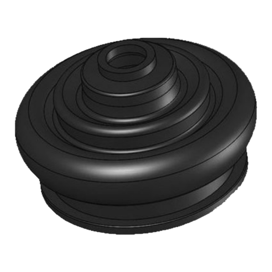
Different variants of the gaiter and gaiter retainer are
available on the market, which differ from each other.
Ensure that you use the enclosed part for repair only!
Quantity
Description
1
Gaiter (required)
1
DOWSIL (formerly Dow Corning) DC4 Electrical
Insulating Compound (required)
DC4 electrical insulating compound can be sourced
from: Element14 / Farnell — Order Code 537019
Advertisement
Table of Contents

Related Manuals for Invacare LiNX


Summary of Contents for Invacare LiNX
- Page 1 Invacare® LiNX DLX-REM400 en Joystick Gaiter Service Manual ........1 de Joystick-Manschette Servicehandbuch.
-
Page 2: Initial Checks
Invacare® LiNX Tools required • 1 x TORX screwdriver bit, size T8 • 1 x TORX screwdriver bit, size T10 • 1 x torque driver capable of taking the T8 and T10 TORX bits and reaching at least 120 cNm torque •... -
Page 3: Component Inspection
Fig. 4-4 Remove rear cover Fig. 4-7 Remove the joystick sub-assembly and gaiter from the chassis Remove the rear cover A by inserting and sliding a thin object, or fingernail, along one of the cover's edges, Carefully remove the joystick sub-assembly and gaiter A whilst gently prising it away from the remote module's from the chassis B. - Page 4 Invacare® LiNX 6 Reassembly Fig. 6-1 Apply electrical insulating compound Using a cotton bud, apply a thin coating of DC4 Electrical Insulating Compound to the middle and lower layers of the gaiter, as highlighted with the grid in figure above.
- Page 5 Fig. 6-8 Re-attach the joystick decorative cover and back cover Re-attach the joystick decorative cover A and back cover B, ensuring all clips are fully engaged. Fig. 6-6 Replace and tighten screws Using the T10 driver, replace and tighten the four screws A to 120 cNm, the screws can be replaced in any order.
- Page 6 Invacare® LiNX die aus der Verwendung nicht zugelassener Teile oder aus bestimmen. Wenn die Manschette so stark beschädigt ist, Wartungsarbeiten resultieren, die von diesem Verfahren dass Fremdkörper oder Fremdstoffe in nicht unerheblicher abweichen. Menge in das Joystick-Gehäuse gelangt sein können, sollte das Fahrpult für eine gründliche interne Untersuchung durch...
- Page 7 Fig. 4-3 Entfernen der vier Schrauben Die vier durch das Entfernen der Zierblende in Fig. 4-5 Entfernen der Schrauben Schritt 2 freigelegten Schrauben A mithilfe des T10-Schraubendrehers entfernen. Die Schrauben können Die vier Schrauben A unter Verwendung des in beliebiger Reihenfolge entfernt werden. Eine Schraube T10-Schraubendrehers entfernen.
- Page 8 Invacare® LiNX der Federhalterung ist normal und kein Anzeichen für eine Beschädigung. Wenn ein Teil beschädigt oder locker ist oder fehlt, sollte das gesamte Fahrpult ausgetauscht oder ggf. zur Wartung an ein Dynamic Controls-Servicezentrum eingeschickt werden. 6 Wiederzusammenbau Fig. 6-1 Auftragen von elektrischer Isoliermasse Mithilfe eines Wattestäbchens eine dünne Schicht...
- Page 9 Fig. 6-3 Einsetzen der Joystick-Baugruppe durch das Chassis und Fig. 6-5 Wiederanschließen der Steckverbinder und Schließen des die Manschette Gehäuses Die Joystick-Baugruppe A von der Innenseite der Die Steckverbinder der internen Flachbandkabel wieder oberen Gehäusehälfte her durch das Chassis B und an den Steckanschlüssen C und D anschließen.
-
Page 10: Antes De Empezar
Invacare® LiNX Die Joystick-Bewegung testen. Hierzu mit dem Joystick bei maximaler Auslenkung eine Kreisbewegung ausführen. Er muss sich uneingeschränkt in alle Richtungen bewegen lassen und stets zur neutralen Mittelstellung zurückkehren, wenn er in beliebiger Position losgelassen wird. Die Einheit mit einem System verbinden. Kontrollieren, ob beim Einschalten eine OON- (Out Of Neutral, Joystick nicht in Mittelstellung) oder andere Störungen vorliegen. - Page 11 2 Equipo Lista de piezas En el mercado existen variantes de la pieza y del fijador que difieren entre sí. Asegúrese de utilizar la pieza incluida solo para la reparación. Cantidad Descripción Pieza (necesaria) Compuesto aislante eléctrico DC4 DOWSIL, antes Dow Corning, (necesario) El compuesto aislante eléctrico DC4 puede proceder de: Element14/Farnell: código de pedido 537019 Fig.
- Page 12 Invacare® LiNX Fig. 4-4 Retire la cubierta trasera Fig. 4-7 Retire el subconjunto del joystick y la pieza del chasis Retire la cubierta trasera A introduciendo y deslizando Retire con cuidado el subconjunto del joystick y la pieza un objeto delgado, o una uña, a lo largo de uno de los A del chasis B.
-
Page 13: Montaje
6 Montaje Fig. 6-1 Aplique compuesto aislante eléctrico Con un bastoncillo de algodón, aplique una fina capa del compuesto aislante eléctrico DC4 en las capas intermedia e inferior de la pieza, como se muestra con la cuadrícula en la figura anterior. Asegúrese de que la grasa se unta de manera uniforme en las zonas correspondientes y no se queda en un único punto. - Page 14 Invacare® LiNX Fig. 6-5 Vuelva a conectar el conector y cierre la carcasa superior e inferior Fig. 6-7 Vuelva a colocar y apriete los tornillos Vuelva a conectar los haces internos de interconexión Con el destornillador T10, vuelva a colocar y apriete los con los conectores C y D.
-
Page 15: Avant De Commencer
libremente en todas las direcciones y volver siempre al centro, que es la posición neutra, al soltarlo desde cualquier 2 Équipement posición. Liste des pièces Conéctelo a un sistema. Compruebe que no permanezca en una posición que no sea neutra y que no presente otros Il existe sur le marché... - Page 16 Invacare® LiNX Fig. 4-1 Retirez la manette du joystick Retirez la manette du joystick : retirez-la directement Fig. 4-4 Retirez le cache arrière du corps du manipulateur, mais NE LA TORDEZ PAS. Si Retirez le cache arrière A en introduisant un objet fin ou la manette est très serrée, vous devrez éventuellement...
- Page 17 moules sur le ressort de retenue est normale et ne constitue pas un signe de détérioration. Si une pièce est détériorée, desserrée ou manquante, le module du manipulateur devra intégralement être remplacé ou, le cas échéant, retourné à un centre de maintenance Dynamic Controls.
- Page 18 Invacare® LiNX Fig. 6-3 Poussez l'ensemble du joystick à travers le châssis et le Fig. 6-5 Rebranchez la douille et fermez les boîtiers supérieur et soufflet d'étanchéité inférieur De la face interne du boîtier supérieur, poussez le Rebranchez les gaines internes d'interconnexion sur les sous-groupe du joystick A à...
-
Page 19: Prima Di Iniziare
Connectez-vous à un système. Vérifiez que la position neutre est conservée à la mise sous tension et qu'il n'y a pas d'autres défauts. Utilisez le module du manipulateur pour conduire un fauteuil roulant, en veillant à ce que le fauteuil roulant se conduise et s'arrête correctement, à... -
Page 20: Descrizione Dell'apparecchiatura
Invacare® LiNX 2 Descrizione dell'apparecchiatura Elenco dei pezzi Sul mercato sono disponibili più varianti differenti della cuffia e del fermo della cuffia. Assicurarsi di utilizzare la parte inclusa solo per le riparazioni. Quantità Descrizione Cuffia (necessaria) DOWSIL (in precedenza Dow Corning) DC4 Electrical Insulating Compound (necessario) DC4 Electrical Insulating Compound può... -
Page 21: Controllo Dei Componenti
Fig. 4-4 Rimuovere il coperchio posteriore Fig. 4-7 Rimuovere il sottogruppo del joystick e la cuffia dal telaio Rimuovere il coperchio posteriore A inserendo e facendo Rimuovere con cautela il sottogruppo del joystick e la scorrere un oggetto sottile, o un'unghia, lungo uno dei cuffia A dal telaio B. - Page 22 Invacare® LiNX 6 Rimontaggio Fig. 6-1 Applicare un composto isolante elettrico Utilizzando un bastoncino cotonato, stendere un leggero strato di DC4 Electrical Insulating Compound sugli anelli centrale e inferiore della cuffia, sulle aree evidenziate in grigio nella figura sopra. Assicurarsi che il grasso sia distribuito in modo uniforme sulle aree evidenziate e non in punti isolati.
- Page 23 Fig. 6-5 Ricollegare il connettore e chiudere l'alloggiamento superiore e inferiore Fig. 6-7 Riposizionare e serrare le viti Ricollegare i telai interni di interconnessione ai connettori Utilizzando il cacciavite T10, riposizionare e serrare le C e D. quattro viti A a 50 cNm, le viti possono essere serrate Controllare che l'altoparlante E sia ancora montato in qualsiasi ordine.
-
Page 24: Antes De Começar
Invacare® LiNX direzioni e che, quando rilasciato, torni in modo uniforme alla posizione neutrale centrale da qualsiasi altra posizione. 2 Equipamento Collegarlo a un sistema. Assicurarsi che non si verifichino Lista de peças errori di posizione non neutrale in fase di accensione o di altro tipo. - Page 25 Fig. 4-1 Remover o parafuso de rosca do joystick Remova o parafuso de rosca do joystick: tirando-o Fig. 4-4 Remover a cobertura traseira diretamente do corpo do módulo do comando, mas NÃO Remova a cobertura traseira A inserindo e fazendo o torça.
- Page 26 Invacare® LiNX Retentor de mola e eixo Fig. 5-1 Retentor de mola e eixo Depois de o fole ser retirado, verifique a condição do retentor de mola A e do eixo. Verifique se existem sinais de danos físicos, incluindo eixos deformados e fendas no retentor de mola.
- Page 27 Fig. 6-3 Pressionar a unidade de joystick através do chassis e do Fig. 6-6 Voltar a colocar os parafusos e apertá-los fole Utilizando a chave de fendas T10, volte a colocar e A partir do lado interior da caixa superior, pressione a apertar os quatro parafusos A a 120 cNm.
-
Page 28: Innan Du Börjar
Invacare® LiNX Ansvar Dynamic Controls ansvarar inte, vare sig uttryckligen eller underförstått, för några skador som uppstår på grund av att oauktoriserade delar används eller att servicen inte följer denna procedur. Begränsningar Proceduren omfattar endast damaskbyte. Om något sekundärt fel, inklusive, men inte begränsat till, intern kontaminering, upptäcks under processen för damaskbyte... - Page 29 returneras, så att en omfattande inre bedömning kan göras av ett Dynamic Controls-servicecenter. Om manöverboxmodulen uppvisar tecken på signifikant mekanisk skada eller stötar ska enheten returneras till ett Dynamic Controls-servicecenter för bedömning. Signifikanta skador är ofta bland annat att enheten inte fungerar som den ska eller att det finns hål i enhetens ram.
- Page 30 Invacare® LiNX 5 Inspektion av komponenter Kontaminering När du har tagit bort damasken, inspektera den synliga joystickmekanismen för tecken på inträngning, inklusive tecken på vätskerester och skräp. Rikta joystickskaftet åt alla riktningar, så du även kan kontrollera om det finns tecken på skräp eller inträngning på...
- Page 31 6 Återmontering Fig. 6-1 Använd dielektrisk pasta Använd en bomullstuss och applicera ett tunt lager dielektrisk pasta till damaskens mellanskikt och nedre skikt, enligt rutmarkeringen i bilden ovan. Kontrollera du har smörjt pastan jämnt hela vägen runt de markerade ytorna, inte bara på ett ställe. Fig.
- Page 32 Invacare® LiNX Fig. 6-8 Sätt tillbaka det dekorativa joystickskyddet och bakstycket Sätt tillbaka det dekorativa joystickskyddet A och bakstycket B, och se till att alla klämmor är helt intryckta. Fig. 6-6 Sätt tillbaka och dra åt skruvarna Sätt tillbaka de fyra skruvarna A och använd T10-skruvmejselbiten för att dra åt dem till 120 cNm.
- Page 33 Notes...
-
Page 36: Making Life's Experiences Possible
Australia: Belgium & Luxemburg: Canada: Danmark: Invacare Australia Pty. Ltd. Invacare nv Invacare Canada L.P. Invacare A/S 1 Lenton Place, North Rocks Autobaan 22 570 Matheson Blvd East, Unit Sdr. Ringvej 37 NSW 2151 B-8210 Loppem DK-2605 Brøndby Australia Tel: (32) (0)50 83 10 10 CDN Mississauga, On.