Table of Contents
Advertisement
Quick Links
Advertisement
Table of Contents
Troubleshooting

Related Manuals for Mitsubishi Electric MELDAS MDS-R Series


Summary of Contents for Mitsubishi Electric MELDAS MDS-R Series
- Page 3 MELDAS is a registered trademark of Mitsubishi Electric Corporation. Other company and product names that appear in this manual are trademarks or registered trademarks of their respective companies.
- Page 5 Introduction Thank you for selecting the Mitsubishi numerical control unit. This instruction manual describes the handling and caution points for using this AC servo/spindle. Incorrect handling may lead to unforeseen accidents, so always read this instruction manual thoroughly to ensure correct usage. Make sure that this instruction manual is delivered to the end user.
- Page 7 Precautions for safety Please read this manual and auxiliary documents before starting installation, operation, maintenance or inspection to ensure correct usage. Thoroughly understand the device, safety information and precautions before starting operation. The safety precautions in this instruction manual are ranked as "WARNING" and "CAUTION". When there is a potential risk of fatal or serious injuries if DANGER handling is mistaken.
- Page 8 WARNING 1. Electric shock prevention Do not open the front cover while the power is ON or during operation. Failure to observe this could lead to electric shocks. Do not operate the unit with the front cover removed. The high voltage terminals and charged sections will be exposed, and can cause electric shocks.
- Page 9 CAUTION 1. Fire prevention Install the units, motors and regenerative resistor on non-combustible material. Direct installation on combustible material or near combustible materials could lead to fires. Always install a no-fuse breaker and contactor on the servo drive unit power input as explained in this manual.
- Page 10 CAUTION 3. Various precautions Observe the following precautions. Incorrect handling of the unit could lead to faults, injuries and electric shocks, etc. (1) Transportation and installation Correctly transport the product according to its weight. Use the motor's hanging bolts only when transporting the motor. Do not transport the machine when the motor is installed on the machine.
- Page 11 CAUTION Store and use the units under the following environment conditions. Environment Unit Motor Operation: 0 to 55°C (with no freezing), Ambient Operation: 0 to 40°C (with no freezing), Storage / Transportation: -15°C to 70°C (Note 2) temperature Storage: -15°C to 70°C (with no freezing) (with no freezing) Operation: 90%RH or less...
- Page 12 CAUTION (2) Wiring Correctly and securely perform the wiring. Failure to do so could lead to abnormal operation of the motor. Do not install a condensing capacitor, surge absorber or radio noise filter on the output side of the drive unit. Correctly connect the output side of the drive unit (terminals U, V, W).
- Page 13 CAUTION (3) Trial operation and adjustment Check and adjust each program and parameter before starting operation. Failure to do so could lead to unforeseen operation of the machine. Do not make remarkable adjustments and changes of parameter as the operation could become unstable.
- Page 14 CAUTION (5) Troubleshooting If a hazardous situation is predicted during power failure or product trouble, use a servomotor with magnetic brakes or install an external brake mechanism. Use a double circuit configuration Shut off with NC brake Shut off with the servomotor control PLC output.
- Page 15 CAUTION (8) Transportation The unit and motor are precision parts and must be handled carefully. According to a United Nations Advisory, the battery unit and battery must be transported according to the rules set forth by the International Civil Aviation Organization (ICAO), International Air Transportation Association (IATA), International Maritime Organization (IMO), and United States Department of Transportation (DOT), etc.
- Page 16 Treatment of waste The following two laws will apply when disposing of this product. Considerations must be made to each law. The following laws are in effect in Japan. Thus, when using this product overseas, the local laws will have a priority. If necessary, indicate or notify these laws to the final user of the product. 1.
-
Page 17: Table Of Contents
CONTENTS 1. Introduction 1-1 System configuration ..........................1-2 1-2 Explanation of type ..........................1-3 1-2-1 Servomotor type......................... 1-3 1-2-2 Servo drive unit type ........................1-4 2. Specifications 2-1 Servomotor .............................. 2-2 2-1-1 Specifications list ........................2-2 2-1-2 Torque characteristics........................ 2-3 2-1-3 Outline dimension drawings....................... - Page 18 6. Installation 6-1 Installing the servomotor ......................... 6-2 6-1-1 Environmental conditions......................6-2 6-1-2 Vibration-resistance strength ..................... 6-2 6-1-3 Precautions for mounting load (Preventing impact on shaft)............. 6-3 6-1-4 Installation direction ........................6-3 6-1-5 Oil and waterproofing measures....................6-3 6-1-6 Cable stress ..........................6-5 6-2 Installation of the units ..........................
- Page 19 9. Adjustment 9-1 Servo adjustment data output function (D/A output) ................9-2 9-1-1 D/A output specifications ......................9-2 9-1-2 Setting the output data....................... 9-2 9-1-3 Setting the output magnification ....................9-3 9-1-4 Current feedback analog output function................... 9-3 9-2 Gain adjustment............................9-4 9-2-1 Current loop gain ........................
- Page 20 Appendix 3. Compliance with European EC Directives Appendix 3-1 Compliance to EC Directives ....................A3-2 Appendix 3-1-1 European EC Directives ..................A3-2 Appendix 3-1-2 Cautions for EC Directive compliance ..............A3-2 Appendix 4. EMC Installation Guidelines Appendix 4-1 Introduction........................... A4-2 Appendix 4-2 EMC instructions ........................A4-2 Appendix 4-3 EMC measures........................
-
Page 21: Introduction
1. Introduction 1-1 System configuration.......................... 1-2 1-2 Explanation of type..........................1-3 1-2-1 Servomotor type .......................... 1-3 1-2-2 Servo drive unit type........................1-4 1 - 1... -
Page 22: System Configuration
1. Introduction 1-1 System configuration Servo drive unit Servo drive unit (MDS-R-V1) (MDS-R-V2) Battery unit (MDS-A-BT) Terminator (A-TM) From NC Regenerative Regenerative resistor unit resistor unit To 24V power supply To 24V power supply To 3rd axis servomotor Grounding Grounding Contactor Contactor (Note) -
Page 23: Explanation Of Type
SER. X X X X X X X X X X X DATE 9809 INPUT 3AC 123V 6.0A Rated output Serial No. OUTPUT 1kW IEC34-1 1994 MITSUBISHI ELECTRIC CORP. MADE IN JAPAN Rated rotation speed SPEED 3000r/min Serial No. SER.No.XXXXXXXXX DATE 03-9 MITSUBISHI ELECTRIC... -
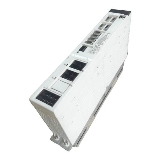
Page 24: Servo Drive Unit Type
OUTPUT 6.6A 3PH 155V 0-240Hz Rated output MANUAL *BNP-C3045 BNDXXXXXXXXX H/W VER.* Current state SERIAL# XXXXXXXXXXX DATE 03/11 Serial No. MITSUBISHI ELECTRIC CORPORATION JAPAN Rating nameplate MDS-R- 1-axis servo drive unit Compatible motor HF Series (1) Motor Low- Medium-inertia Drive type... -
Page 25: Specifications
2. Specifications 2-1 Servomotor............................2-2 2-1-1 Specifications list......................... 2-2 2-1-2 Torque characteristics ......................... 2-3 2-1-3 Outline dimension drawings ......................2-4 2-2 Servo drive unit ..........................2-16 2-2-1 Installation environment conditions ................... 2-16 2-2-2 Specifications list........................2-16 2-2-3 Outline dimension drawings ...................... 2-17 2-2-4 Explanation of each part...................... -
Page 26: Servomotor
2. Specifications 2-1 Servomotor 2-1-1 Specifications list (1) HF Series HF□□-A47/A42 4000r/min Servomotor type 3000r/min Series Series HF44 HF74 HF53 HF103 HF153 HF203 HF353 Compatible servo drive MDS-R-V1/V2- 20(40) 20(40) 20(40) (80) (80) unit type (Note 4) Rated output [kW] 0.75 0.67 1.16... -
Page 27: Torque Characteristics
2. Specifications 2-1-2 Torque characteristics [ HF44 ] [ HF74 ] Compatible unit R-V1/V2-20 (40) Compatible unit R-V1/V2-20 (40) Short time operation range Short time operation range Continuous Continuous operation range operation range 2000 4000 2000 4000 Rotation speed [r/min] Rotation speed [r/min] [ HF53 ] [ HF103 ]... -
Page 28: Outline Dimension Drawings
2. Specifications 2-1-3 Outline dimension drawings • HF44S-A47 • HF74S-A47 • HF44T-A47 • HF74T-A47 [Unit: mm] 4-ø6.6 mounting hole Use a hexagon 39.5 45º socket bolt. ø118 ø100 Oil seal SC15307 19.5 Detector connector Power connector MS3102A20-29P MS3102A18-10P 4-ø6.6 mounting hole Use a hexagon Plain washer 8 socket bolt. - Page 29 2. Specifications • HF44BS-A47 • HF74BS-A47 • HF44BT-A47 • HF74BT-A47 [Unit: mm] 39.5 45º ø118 ø100 Oil seal SC15307 4-ø6.6 mounting hole Use a hexagon 19.5 socket bolt. 67.5 Detector connector Power connector MS3102A20-29P Brake connector MS3102A18-10P CM10-R2P 4-ø6.6 mounting hole Use a hexagon Plain washer 8 socket bolt.
- Page 30 2. Specifications • HF44S-A42 • HF74S-A42 • HF44T-A42 • HF74T-A42 [Unit: mm] 45º ø118 ø100 Oil seal SC15307 4-ø6.6 mounting hole Use a hexagon 21.5 socket bolt. Detector connector Power connector MS3102A22-14P MS3102A18-10P 4-ø6.6 mounting hole Use a hexagon Plain washer 8 socket bolt.
- Page 31 2. Specifications • HF44BS-A42 • HF74BS-A42 • HF44BT-A42 • HF74BT-A42 [Unit: mm] 45º ø118 ø100 Oil seal SC15307 4-ø6.6 mounting hole Use a hexagon 21.5 socket bolt. Detector connector Power connector MS3102A20-14P Brake connector MS3102A18-10P CM10-R2P 4-ø6.6 mounting hole Use a hexagon Plain washer 8 socket bolt.
- Page 32 2. Specifications • HF53S-A47 • HF103S-A47 • HF153S-A47 • HF53T-A47 • HF103T-A47 • HF153T-A47 [Unit: mm] 39.5 45º ø145 ø165 13.5 4- ø9 mounting hole 19.5 Use a hexagon socket bolt. Detector connector Power connector MS3102A20-29P MS3102A18-10P 45º ø145 ø165 Tightening torque •...
- Page 33 2. Specifications • HF53BS-A47 • HF103BS-A47 • HF153BS-A47 • HF53BT-A47 • HF103BT-A47 • HF153BT-A47 [Unit: mm] 39.5 45º ø145 ø165 13.5 21.5 4-ø9 mounting hole Use a hexagon socket bolt. Power connector Detector connector MS3102A18-10P MS3102A20-29P Brake connector CM10-R2P 45º ø145 ø165 Tightening torque...
- Page 34 2. Specifications • HF53S-A42 • HF103S-A42 • HF153S-A42 • HF53T-A42 • HF103T-A42 • HF153T-A42 [Unit: mm] 45º ø145 ø165 13.5 4-ø9 mounting hole 21.5 Use a hexagon socket bolt. Detector connector Power connector MS3102A22-14P MS3102A18-10P 45º ø145 ø165 Tightening torque •...
- Page 35 2. Specifications • HF53BS-A42 • HF103BS-A42 • HF153BS-A42 • HF53BT-A42 • HF103BT-A42 • HF153BT-A42 [Unit: mm] 45º ø145 ø165 13.5 21.5 4-ø9 mounting hole 73.5 Use a hexagon socket bolt. Power connector Detector connector MS3102A18-10P MS3102A22-14P Brake connector CM10-R2P 45º ø145 ø165 Tightening torque...
- Page 36 2. Specifications • HF203S-A47 [Unit: mm] 39.5 45º ø200 ø230 79.8 19.5 Power connector 4-ø13.5 mounting hole MS3102A22-22P Detector connector Use a hexagon socket bolt. MS3102A20-29P (Note 1) Use a friction coupling (Spun ring, etc.) to connect with the load. (Note 2) Attach the cannon connector facing downward to improve the splash-proof performance.
- Page 37 2. Specifications • HF203S-A42 [Unit: mm] 149.5 45º ø200 ø230 79.8 21.5 Power connector 4-ø13.5 mounting hole MS3102A22-22P Detector connector Use a hexagon socket bolt. MS3102A22-14P (Note 1) Use a friction coupling (Spun ring, etc.) to connect with the load. (Note 2) Attach the cannon connector facing downward to improve the splash-proof performance.
- Page 38 2. Specifications • HF353S-A47 [Unit: mm] 39.5 45º ø200 ø230 119.8 19.5 4-ø13.5 mounting hole Detector connector Use a hexagon socket bolt. MS3102A20-29P Power connector MS3102A22-22P (Note 1) Use a friction coupling (Spun ring, etc.) to connect with the load. (Note 2) Attach the cannon connector facing downward to improve the splash-proof performance.
- Page 39 2. Specifications • HF353S-A42 [Unit: mm] 189.5 45º ø200 ø230 119.8 21.5 4-ø13.5 mounting hole Detector connector Use a hexagon socket bolt. MS3102A22-14P Power connector MS3102A22-22P (Note 1) Use a friction coupling (Spun ring, etc.) to connect with the load. (Note 2) Attach the cannon connector facing downward to improve the splash-proof performance.
-
Page 40: Servo Drive Unit
2. Specifications 2-2 Servo drive unit 2-2-1 Installation environment conditions Common installation environment conditions for servo drive unit are shown below. Ambient temperature Operation: 0 to 55°C (with no freezing), Storage / Transportation: -15°C to 65°C (with no freezing) Operation: 90%RH or less (with no dew condensation) Ambient humidity Storage / Transportation: 90%RH or less (with no dew condensation) Environ-... -
Page 41: Outline Dimension Drawings
2. Specifications 2-2-3 Outline dimension drawings (1) 1-axis servo drive unit • MDS-R-V1-20 • MDS-R-V1-40 ø6 hole Wiring allowance (Note3) Intake (Note3) (Note3) Square hole (Note 1) Attach packing around the square hole for sealing. (Note 1) (Note 2) The intake fan can be mounted only at the top as shown above. (Note 3) Required wind passage space 2-M5 screw hole... - Page 42 2. Specifications • MDS-R-V1-60 • MDS-R-V1-80 ø6 hole Wiring allowance (Note3) Intake (Note3) (Note3) Square hole (Note 1) Attach packing around the square hole for sealing. (Note 1) (Note 2) The intake fan can be mounted only at the top as shown above. (Note 3) Required wind passage space 2-M5 screw hole...
- Page 43 2. Specifications (2) 2-axis servo drive unit • MDS-R-V2-2020 • MDS-R-V2-4040 • MDS-R-V2-4020 ø6 hole Wiring allowance (Note2) Intake Intake (Note2) (Note2) Square hole (Note 1) Attach packing around the square hole for sealing. (Note 1) (Note 2) Required wind passage space 2-M5 screw hole Unit [mm] Panel mounting...
- Page 44 2. Specifications • MDS-R-V2-6040 • MDS-R-V2-8040 • MDS-R-V2-8080 • MDS-R-V2-6060 • MDS-R-V2-8060 ø6 hole Wiring allowance (Note2) Intake Intake (Note2) (Note2) Square hole (Note 1) Attach packing around the square hole for sealing. (Note 1) (Note 2) Required wind passage space 2-M5 screw hole Unit [mm] Panel mounting...
-
Page 45: Explanation Of Each Part
2. Specifications 2-2-4 Explanation of each part (1) Explanation of each servo drive unit part <1> <1> <2> <2> <3> <3> <4> <4> <5> <5> <6> <6> <7> <7> <8> <8> <9> <10> <10> <11> <12> <12> <13> <13> <14> <14>... -
Page 47: Characteristics
3. Characteristics 3-1 Drive unit characteristics ........................3-2 3-1-1 Heating value ..........................3-2 3-1-2 Overload protection characteristics..................... 3-3 3-2 Servomotor............................3-7 3-2-1 Shaft characteristics ........................3-7 3-2-2 Magnetic brake..........................3-8 3-2-3 Dynamic brake characteristics ....................3-11 3 - 1... -
Page 48: Drive Unit Characteristics
3. Characteristics 3-1 Drive unit characteristics 3-1-1 Heating value The heating value of each servo drive unit is the heating value at stall output. Servo drive unit type Heating value [W] Servo drive unit type Heating value [W] Inside Outside Inside Outside MDS-R-... -
Page 49: Overload Protection Characteristics
3. Characteristics 3-1-2 Overload protection characteristics The servo drive unit has an electronic thermal relay to protect the servomotor and servo drive unit from overloads. The operation characteristics of the electronic thermal relay are shown below when standard parameters (SV021=60, SV022=150) are set. If overload operation over the electronic thermal relay protection curve shown below is carried out, overload 1 (alarm 50) will occur. - Page 50 3. Characteristics (3) Motor HF53 HF53 Overload protection characteristics 10000 When rotating When stopped 1000 Current (stall %) (4) Motor HF103 HF103 Overload protction characteristics 10000 When rotating When stopped 1000 Current (stall %) 3 - 4...
- Page 51 3. Characteristics (5) Motor HF153 HF153 Overload protection characteristics 10000 When rotating When stopped 1000 Current (stall %) (6) Motor HF203 HF203 Overload protection characteristics 10000 When rotating When stopped 1000 Current (stall %) 3 - 5...
- Page 52 3. Characteristics (7) Motor HF353 HF353 Overload protection characteristics 10000 When rotating When stopped 1000 Current (stall %) 3 - 6...
-
Page 53: Servomotor
3. Characteristics 3-2 Servomotor 3-2-1 Shaft characteristics There is a limit to the load that can be applied on the motor shaft. Make sure that the load applied on the radial direction and thrust direction, when mounted on the machine, is below the tolerable values given below. -
Page 54: Magnetic Brake
3. Characteristics 3-2-2 Magnetic brake 1. The axis will not be mechanically held even when the dynamic brakes are used. If the machine could drop when the power fails, use a servomotor with magnetic brakes or provide an external brake mechanism as holding means to prevent dropping. - Page 55 3. Characteristics (2) Magnetic brake characteristics Motor model HF53B HF44B HF203B HF103B HF74B HF353B HF153B Item Spring braking type safety brakes Type (Note 1) Rated voltage 24VDC Rated current at 20°C 0.38 Capacity Static friction torque (N·m) 43.1 Inertia (Note 2) (kg·cm Release delay time (Note 3) 0.03...
- Page 56 3. Characteristics (3) Magnetic brake power supply 1. Always install a surge absorber on the brake terminal when using DC OFF. 2. Do not pull out the cannon plug while the brake power is ON. The cannon CAUTION plug pins could be damaged by sparks. (a) Brake excitation power supply Prepare a brake excitation power supply that can accurately ensure the attraction current in consideration of the voltage fluctuation and excitation coil temperature.
-
Page 57: Dynamic Brake Characteristics
3. Characteristics 3-2-3 Dynamic brake characteristics If a servo alarm that cannot control the motor occurs, the dynamic brakes will function to stop the servomotor regardless of the parameter settings. (1) Deceleration torque The dynamic brake uses the motor as a generator, and obtains the deceleration torque by consuming that energy with the dynamic brake resistance. - Page 58 3. Characteristics (2) Coasting rotation distance during emergency stop The distance that the motor coasts (angle for rotary axis) when stopping with the dynamic brakes can be approximated with the following expression. {te + (1 + + B)} ▪ ▪ ▪...
-
Page 59: Dedicated Options
4. Dedicated Options 4-1 Regenerative option ........................... 4-2 4-1-1 Regenerative resistor unit ......................4-4 4-1-2 Regenerative resistor ........................4-6 4-2 Machine side detector ........................4-8 4-3 Battery and terminator option......................4-9 4-3-1 Terminator (A-TM)........................4-9 4-3-2 Battery (ER6)..........................4-10 4-3-3 Battery unit (MDS-A-BT) ......................4-11 4-4 Relay terminal block (MR-J2CN3TM) .................... -
Page 60: Regenerative Option
4. Dedicated Options 4-1 Regenerative option For the regenerative option, always select a regenerative resistor unit or regenerative resistor in the correct combination for each servo drive unit. Refer to "Appendix 2-2 Selecting the regenerative resistor" for details on selecting the regenerative option. The regenerative resistor generates heats, so wire and install the unit while taking care to safety. - Page 61 4. Dedicated Options Parameter Abbrev. Explanation name Regenerative SV036 PTYP* resistor type rtyp emgx Explanation Select the regenerative resistor type. Setting Regenerative resistor or regenerative resistor unit rtyp 0 to 1 Setting prohibited GZG200W26OHMJ GZG300W20OHMJ MR-RB32 or GZG200W1200HMJ 3 units connected in parallel MR-RB30 or GZG200W39OHMJ 3 units connected in parallel...
-
Page 62: Regenerative Resistor Unit
4. Dedicated Options 4-1-1 Regenerative resistor unit (1) Specifications Regenerative Regenerative Resistance Mass (kg) option type power (W) value (Ω) MR-RB30 MR-RB31 MR-RB32 MR-RB50 MR-RB51 MR-RB65 (2) Outline dimension drawings MR-RB30, MR-RB31, MR-RB32 [Unit: mm] 4 - 4... - Page 63 4. Dedicated Options MR-RB50, MR-RB51 [Unit: mm] MR-RB65 [Unit: mm] 2-ø10 mounting hole 4 - 5...
-
Page 64: Regenerative Resistor
4. Dedicated Options 4-1-2 Regenerative resistor (1) Outline dimension drawings GZG80W26OHMJ [Unit: mm] Ø3.2×2 mounting hole GZG200W20OHMJ, GZG200W26OHMJ, GZG200W39OHMJ, GZG200W120OHMJ [Unit: mm] Ø4.3×2 mounting hole GZG400W13OHMJ, GZG400W8OHMJ [Unit: mm] Ø5.5×2 mounting hole GZG300W20OHMJ, GZG300W39OHMJ [Unit: mm] Ø5.5×2 mounting hole 4 - 6... - Page 65 4. Dedicated Options GRZG400-2OHMJ [Unit: mm] Ø5.5×2 mounting hole When using the regenerative resistor, a protective cover must be mounted on the machine side so that flammable matters do not come in contact or adhere on CAUTION the device. 4 - 7...
-
Page 66: Machine Side Detector
4. Dedicated Options 4-2 Machine side detector In MDS-R series, the relative position specifications and oblong wave output linear scale are available. The machine side detectors are all special order parts, and must be prepared by the user. Relative position detector Select a machine side relative position detector that has specifications that are correspond to the following output signal. -
Page 67: Battery And Terminator Option
4. Dedicated Options 4-3 Battery and terminator option A battery unit must be used with the absolute position system. A battery unit or terminator must be connected on each NC communication bus line. Select the unit according to the system specifications. •... -
Page 68: Battery (Er6)
4. Dedicated Options 4-3-2 Battery (ER6) This battery is built into the servo drive unit. One battery is provided for each absolute position control axis' servo drive unit. (1) Specifications Battery unit specifications Type Nominal voltage 3.6V Nominal capacity 2000mAh Battery continuous backup time Approx. -
Page 69: Battery Unit (Mds-A-Bt)
4. Dedicated Options 4-3-3 Battery unit (MDS-A-BT) This battery is installed outside the servo drive unit. This battery unit backs up the absolute position data of the multiple servo axes connected to each NC bus line. This battery unit also functions as a terminator. -
Page 70: Relay Terminal Block (Mr-J2Cn3Tm)
4. Dedicated Options 4-4 Relay terminal block (MR-J2CN3TM) Signals input/output from the CN9 connector on the front of the servo drive unit can be led to the terminal block. Connect the terminal block to the CN9 connector with an SH21 cable. Abbrev. -
Page 71: Cables And Connectors
4-5 Cables and connectors 4-5-1 Cable connection diagram The cables and connectors that can be ordered from Mitsubishi Electric Corp. as option parts are shown below. Cables can only be ordered in the designated lengths shown on the following pages. Purchase a connector set, etc., to create special length cables. -
Page 72: Cable And Connector Options
4. Dedicated Options 4-5-2 Cable and connector options (1) Cables Item Model Contents (1) NC bus cable SH21 Servo drive unit side connector Servo drive unit side CN1A, (3M) connector (3M) Length: CN1B 0.35, 0.5, 0.7, 1, Connector : 10120-6000EL Connector : 10120-6000EL Shell kit : 10320-3210-000... - Page 73 4. Dedicated Options (2) Connector sets Item Model Contents (1) NC bus cable connector set FCUA-CS000 Servo drive unit side connector Servo drive unit side CN1A, (3M) connector (3M) CN1B, Connector : 10120-6000EL Connector : 10120-6000EL Shell kit : 10320-3210-000 Shell kit : 10320-3210-000 Servo drive unit side connector...
- Page 74 4. Dedicated Options Item Model Contents (3) Power supply Straight PWCE18-10S Servomotor side power supply motor connector set for IP67 connector (DDK) Compliant cable range power HF44, 74, compati- Plug : CE05-6A18-10SD-B- ø10.5 to ø14.1mm supply HF53, 103, 153 Clamp : CE3057-10A-1 (D256) Angle PWCE18-10L Servomotor side power...
- Page 75 4. Dedicated Options Item Model Contents (5) Main circuit power supply connector for RCN30S Drive unit main circuit power CN30 MDS-R-V1/V2 supply connector For AWG14, 16 (DDK) Contact : DK-5200S-04R Housing : DK-5RECSLP1-100 RCN30M Drive unit motor power supply connector For AWG10, 12 (DDK) Contact : DK-5200M-06R...
-
Page 77: Peripheral Devices
5. Peripheral Devices 5-1 Selecting the wire size ........................5-2 5-1-1 Example of wires by unit ......................5-2 5-2 Selection of no-fuse breaker and contactor ..................5-4 5-2-1 Selection of no-fuse breaker ....................... 5-4 5-2-2 Selection of contactor........................5-5 5-3 Selection of earth leakage breaker ....................5-6 5-4 Selection of control power supply ...................... -
Page 78: Selecting The Wire Size
5. Peripheral Devices 5-1 Selecting the wire size 5-1-1 Example of wires by unit Selected wires must be able to tolerate rated current of the unit’s terminal to which the wire is connected. How to calculate tolerable current of an insulated wire or cable is shown in “Tolerable current of electric cable”... - Page 79 5. Peripheral Devices (3) 600V bridge polyethylene insulated wire (IC) 105 C product (Example according to JEAC8001) Motor output Control power Terminal Power input (24VDC) CN31L、CN31M name Regenerative option CN30 CN22 (LU,LV,LW, CN30 (L1, L2, L3, Magnetic brake (P, C) (MU,...
-
Page 80: Selection Of No-Fuse Breaker And Contactor
Select the no-fuse breaker as in the expression below. Unit type V1-20 V1-40 V1-60 V1-80 MDS-R- Recommended NF30- NF30- NF30- NF50- breaker (Mitsubishi Electric CS3P-15A CS3P-20A CS3P-30A CW3P-40A Corp.: option part) Rated current of the recommended breaker Unit type V2-2020 V2-4020 V2-4040... -
Page 81: Selection Of Contactor
Select the contactor as in the expression below. Unit type V1-20 V1-40 V1-60 V1-80 MDS-R- Recommended S-N12 S-N18 S-N20 S-N25 contactor (Mitsubishi Electric -AC200V -AC200V -AC200V -AC200V Corp.: option part) Free-air thermal current of the recommended contactor Unit type V2-2020 V2-4020... -
Page 82: Selection Of Earth Leakage Breaker
5. Peripheral Devices 5-3 Selection of earth leakage breaker When installing an earth leakage breaker, select the breaker on the following basis to prevent the breaker from malfunctioning by the higher frequency earth leakage current generated in the servo drive unit. -
Page 83: Selection Of Control Power Supply
5. Peripheral Devices 5-4 Selection of control power supply For the control power supply of MDS-R Series, choose the stabilized power supply that satisfies the specifications below. (1) Power supply specification External power supply unit 24VDC ±10% Output voltage 200mV max. Ripple Select the external power supply unit that satisfies the current or rush current specification of the drive unit control power supply... -
Page 84: Noise Filter
5. Peripheral Devices 5-5 Noise filter (1) Selection Use an EMC noise filter if the noise conducted to the power line must be reduced. Select an EMC noise filter taking the drive unit's input rated voltage and input rated current into consideration. (2) Noise filter mounting position Install the noise filter to the drive unit’s power input as the diagram below indicates. -
Page 85: Surge Absorber
5. Peripheral Devices 5-6 Surge absorber When controlling a magnetic brake of a servomotor in DC OFF circuit, a surge absorber must be installed to protect the relay contacts and brakes. Commonly a varistor is used. (1) Selection of varistor When a varistor is installed in parallel with the coil, the surge voltage can be adsorbed as heat to protect a circuit. -
Page 86: Relay
5. Peripheral Devices 5-7 Relay Use the following relays for the input/output interface (contactor control signal or motor break control signal: CN9). Interface name Selection example Use a minute signal relay (Example: twin contact) to prevent a contact defect. For digital input signal (CN9) <Example>... -
Page 87: Installation
6. Installation 6-1 Installing the servomotor ........................6-2 6-1-1 Environmental conditions ......................6-2 6-1-2 Vibration-resistance strength ...................... 6-2 6-1-3 Precautions for mounting load (Preventing impact on shaft) ............6-3 6-1-4 Installation direction........................6-3 6-1-5 Oil and waterproofing measures ....................6-3 6-1-6 Cable stress .......................... -
Page 88: Installing The Servomotor
6. Installation 6-1 Installing the servomotor 1. Do not hold the cables, shaft or detector when transporting the motor. Failure to observe this could result in breakage and injury. 2. Securely fix the motor onto the machine. Improper fixing could cause the motor to dislocate and result in injury. -
Page 89: Precautions For Mounting Load (Preventing Impact On Shaft)
6. Installation 6-1-3 Precautions for mounting load (Preventing impact on shaft) (1) When using the servomotor with keyway, use the screw hole on the end of the shaft to mount the pulley onto the Servom otor Double-end stud shaft. When mounting, insert a double-end stud into the shaft's screw hole, and contact a washer against the end of the coupling. - Page 90 6. Installation (3) When installing the servomotor horizontally, set the power cable and detector cable to face downward. When installing vertically or with an inclination, provide a cable trap. Cable trap When installed horizontally When installed vertically 1. The servomotors, including those having IP67 specifications, do not have a completely waterproof (oil-proof) structure.
-
Page 91: Cable Stress
6. Installation (6) When installing on the top of the shaft end, make sure that Gear oil from the gear box, etc., does not enter the servomotor. Lubricating oil The servomotor does not have a waterproof structure. Servomotor 6-1-6 Cable stress (1) Carefully consider the cable clamping method so that bending stress and the stress from the cable's own weight is not applied on the cable connection section. -
Page 92: Installation Of The Units
6. Installation 6-2 Installation of the units 1. Install the unit on noncombustible material. Direct installation on combustible material or near combustible materials may lead to fires. 2. Follow the instructions in this manual and install the unit while allowing for the unit mass. -
Page 93: Installation Direction And Clearance
6. Installation 6-2-2 Installation direction and clearance Wire each unit in consideration of the maintainability and the heat dissipation, also secure sufficient space for ventilation. (1) Installation clearance 100mm 100mm 60mm or more Exhaust or more or more 80mm or more 60mm 10mm 10mm... - Page 94 6. Installation (2) Panel structure of the unit back face The type "(a)" that has substantial cooling effect is recommended. (a) Back face inlet type (b) Side face inlet type Filter Filter Install a partition plate inside Cooling will be more high- to separate inlet and exhaust.
- Page 95 6. Installation (3) Cooling fan position 90mm width 60mm width unit unit Design the inlet so that it is the position of the cooling fan. Make the inlet and exhaust size more than the area that is a total of the cooling CAUTION fan area.
-
Page 96: Prevention Of Foreign Matter Entry
6. Installation 6-2-3 Prevention of foreign matter entry Treat the cabinet with the following items. • Make sure that the cable inlet is dust and oil proof by using packing, etc. • Make sure that the external air does not enter inside through heat radiating holes, etc. -
Page 97: Heating Value
6. Installation 6-2-5 Heating value The heating value of each servo drive unit is the heating value at stall output. Servo drive unit type Heating value [W] Servo drive unit type Heating value [W] Inside Outside Inside Outside MDS-R- MDS-R- panel panel panel... -
Page 98: Heat Radiation Countermeasures
6. Installation 6-2-6 Heat radiation countermeasures (1) Heat radiation countermeasures in the control panel In order to secure reliability and life, design the temperature in the panel so that the ambient temperature of each unit is 55°C or less. If the heat accumulates at the top of the unit, etc., install a fan or heat exchanger so that the temperature in the panel remains constant. - Page 99 6. Installation The following shows a calculation example for considering heat radiation countermeasures. <Control panel outline dimension (assumption) > When installing four units which have the heating value in the panel of 15W Top of panel inside Fan for agitating Heat radiation area (A): When a bottom section contacts with a machine A = 0.6 x 0.3 + 0.6 x 0.6 x 2 + 0.6 x 0.3 x 2 = 1.26 (m (Top face) (Front/back face) (Side face)
- Page 100 6. Installation (2) Heat radiation countermeasures outside the control panel Measure the temperature at 40mm form tops of all units, and design the temperature rise so that it is 20°C or less against the ambient temperature. If the temperature rise at the temperature measurement position exceeds 20°C, consider adding a fan.
-
Page 101: Noise Measures
6. Installation 6-3 Noise measures Noise includes "propagation noise" generated from the power supply or relay, etc., and propagated along a cable causing the power supply unit or drive unit to malfunction, and "radiated noise" propagated through air from a peripheral device, etc. causing the power supply unit or drive unit to malfunction. - Page 102 6. Installation (Example) Drive system <5> <7> <2> <7> <2> <1> Sensor Drive Instru- power Receiver unit supply ment <6> <3> <4> <8> Sensor Servomotor Spindle motor Noise propagation Measures path When devices such as instrument, receiver or sensor, which handle minute signals and are easily affected by noise, or the signal wire of these devices, are stored in the same panel as the drive units and the wiring is close, the device could malfunction due to airborne propagation of the noise.
-
Page 103: Wiring And Connection
7. Wiring and Connection 7-1 Part system connection diagram......................7-3 7-2 Main circuit and control circuit connectors ..................7-4 7-2-1 Connector pin assignment ......................7-4 7-2-2 Main circuit and control circuit connector signal names and applications ........7-5 7-3 NC and drive unit connection ......................7-6 7-4 Motor and detector connection ...................... - Page 104 7. Wiring and Connection 1. Wiring work must be done by a qualified technician. 2. Wait at least 15 minutes after turning the power OFF and check the voltage with a tester, etc. before starting wiring. Failure to observe this could lead to DANGER electric shocks.
-
Page 105: Part System Connection Diagram
7. Wiring and Connection 7-1 Part system connection diagram Mitsubishi MDS-R-V1- MDS-R-V2- MDS-A-BT- SV1, 2 CN1A CN1B CN1A CN1B (CSH21) CN3L CN3L Machine side Machine side detector detector CN3M Machine side detector CN2L CN2L CN2M 24V power CN22 CN22 No-fuse Contactor breaker Motor... -
Page 106: Main Circuit And Control Circuit Connectors
7. Wiring and Connection 7-2 Main circuit and control circuit connectors Do not apply a voltage other than that specified on each terminal. Failure to CAUTION observe this item could lead to rupture or damage, etc. 7-2-1 Connector pin assignment Unit MDS-R-V1- MDS-R-V2-... -
Page 107: Main Circuit And Control Circuit Connector Signal Names And Applications
7. Wiring and Connection 7-2-2 Main circuit and control circuit connector signal names and applications The following table shows the details for each terminal block signal. Name Signal name Description Main circuit Main circuit power supply input terminal L1 . L2 . L3 power supply Connect a 3-phase 200 to 230VAC, 50/60Hz power supply. -
Page 108: Nc And Drive Unit Connection
7. Wiring and Connection 7-3 NC and drive unit connection The NC bus cables are connected from the NC to each drive unit so that they are laid in a straight line from the NC to the terminal connector (battery unit). And up to 7 axes can be connected per system. (Note that the number of connected axes is limited by the CNC. -
Page 109: Motor And Detector Connection
7. Wiring and Connection 7-4 Motor and detector connection 7-4-1 Connection of servomotor HF Series The OSA104S2 or OSA17 detector can be used. (1) Connection of HF44(B)/HF74(B)/HF53(B)/HF103(B)/HF153(B) MDS-R-V1/V2 Detector connector Motor side detector connector CN2L/M For OSA104S2 For OSA17 Option cable: CNV2E (Refer to Appendix 1 for details on manufacturing MS3102A22-14P MS3102A20-29P... - Page 110 7. Wiring and Connection (2) Connection of HF203(B)/HF353(B) MDS-R-V1/V2 Detector connector Motor side detector connector CN2L/M For OSA104S2 For OSA17 Option cable: CNV2E (Refer to Appendix 1 for details on manufacturing MS3102A22-14P MS3102A20-29P Signal Signal the cable.) CN2L Max. 30m Motor brake wiring (Refer to "7-8 Wiring of the motor brake"...
- Page 111 7. Wiring and Connection (3) Connecting the linear scale (for oblong wave data output) Detector connector : CN3L Pin No. No.9 No.1 No.10 No.2 Name Name MDS-R-V1/V2 P5(+5V) ABZSEL* CN2L CNV2E CN3L Max.30m CN31L U,V,W,PE Table Linear scale Servomotor 7 - 9...
-
Page 112: Connection Of Main Circuit Power Supply
7. Wiring and Connection 7-5 Connection of main circuit power supply 1. Make sure that the power supply voltage is within the specified range of the servo drive unit. Failure to observe this could lead to damage or faults. 2. For safety purposes, always install a no fuse breaker (NFB), and make sure that the circuit is cut off when an error occurs or during inspections. -
Page 113: Connection Of Regenerative Resistor
7. Wiring and Connection 7-6 Connection of regenerative resistor The MDS-R Series does not have a built-in regenerative resistor. If the load inertia is small, there will be no problem with the capacitor regeneration (regenerative resistance is not required as the circuit is charged with the capacitor in the drive unit). -
Page 114: Connection Of External Regenerative Resistor
7. Wiring and Connection 7-6-2 Connection of external regenerative resistor Connect the regenerative resistor across P-C of CN30. (1) Connection of one resistor GZG200W26OHMJ, GZG300W20OHMJ GZG80W26OHMJ, GZG400W13OHMJ, GZG400W8OHMJ External optional regenerative resistor Install a protective cover to prevent foreign matter (cutting chips, cutting oil, etc.) from entering the regenerative resistor or the regenerative resistor from being touched directly. - Page 115 7. Wiring and Connection (3) Connection of four resistors in serial GRZG400-2OHMJ External optional regenerative resistor Install a protective cover to prevent foreign matter (cutting chips, cutting oil, etc.) from entering the regenerative resistor or the regenerative resistor from being touched directly. CN30 Use a twisted flame retardant wire.
-
Page 116: Wiring Of Contactors
7. Wiring and Connection 7-7 Wiring of contactors 7-7-1 Contactor control Insert a contactor (magnetic contactor) in the main circuit power supply input (L1, L2, L3) of the servo drive unit, and shut off the power supply input when an emergency stop or servo alarm occurs. When an emergency stop or servo alarm occurs, the servo drive unit stops the motor using deceleration control or dynamic brakes. -
Page 117: Contactor Control Signal (Mc) Output Circuit
7. Wiring and Connection 7-7-2 Contactor control signal (MC) output circuit A relay or photo coupler can be driven. When using an inductive load, install a diode. (Tolerable current: 40mA or less, rush current: 100mA or less) Contactor The servo drive unit will fail if the diode polarity is MDS-R-V1/V2 incorrect. -
Page 118: Contactor Power On Sequences
7. Wiring and Connection 7-7-3 Contactor power ON sequences When using the contactor control output (CN9 connector: MC) for the MDS-R-V1/V2 servo drive unit, the main circuit power supply is turned ON with the sequence shown below. In the 200ms interval after the drive unit emergency stop input is canceled, the contactor contact fusion is checked by discharging the PN bus voltage with the regenerative resistor. -
Page 119: Monitor Of Contactor Operation
7. Wiring and Connection 7-7-5 Monitor of contactor operation The contactor operation can be monitored by inputting the contactor B contact to the MDS-R-V1/V2 DI signal and setting the parameter. The contactor error alarm (5F) will occur if the contactor turns ON during READY OFF, or if the contactor turns OFF during READY ON. -
Page 120: Wiring Of The Motor Brake
7. Wiring and Connection 7-8 Wiring of the motor brake The magnetic brakes of servomotors with magnetic brakes are driven by the control signal (MBR) output by the servo drive unit MDS-R-V1/V2. The servo drive unit releases the brakes when the motor is ON. (Servo ON means when torque is generated in the motor.) No parameters need to be set to use the motor brake control output (MBR). -
Page 121: Motor Brake Release Sequence
7. Wiring and Connection 7-8-2 Motor brake release sequence The motor brake control output (CN9 connector: MBR) releases the motor brakes with the sequence shown below when canceling the emergency stop. Because the brake is released after the start of the power ON to the servomotor, dropping due to an uncontrolled state does not occur. -
Page 122: Wiring Of An External Emergency Stop
7. Wiring and Connection 7-9 Wiring of an external emergency stop 7-9-1 External emergency stop setting Besides the main emergency stop input from the NC bus line (CN1A, CN1B), double-protection when an emergency stop occurs is possible by directly inputting an independent external emergency stop to the servo drive unit. -
Page 123: External Emergency Stop Signal (Emgx) Input Circuit
7. Wiring and Connection 7-9-2 External emergency stop signal (EMGX) input circuit Issue a signal with a relay or open collector transistor. When using an external power supply, the power supply for the contactor control output and motor brake control output is the same external power supply. -
Page 124: External Emergency Stop Operation Sequence
7. Wiring and Connection 7-9-3 External emergency stop operation sequence If only an external emergency stop is input when "external emergency stop valid" is set (the main emergency stop is not input), "In external emergency stop state" (warning EA) will be detected. Then, the system will enter the emergency stop state. -
Page 125: Setup
8. Setup 8-1 Servo drive unit initial settings..................... 8-2 8-1-1 Setting the rotary switch...................... 8-2 8-1-2 Transition of LED display after power is turned ON............8-3 8-2 Setting the initial parameters ....................... 8-4 8-2-1 Setting the standard parameters..................8-4 8-2-2 Limitations to electronic gear setting value ................. 8-8 8-2-3 Standard parameter list according to servomotor ............... -
Page 126: Servo Drive Unit Initial Settings
8. Setup 8-1 Servo drive unit initial settings 8-1-1 Setting the rotary switch Before turning the power ON, the axis No. must be set with the rotary switch. The rotary switch settings will be validated when the units are turned ON. Rotary switch Set axis No. -
Page 127: Transition Of Led Display After Power Is Turned On
8. Setup 8-1-2 Transition of LED display after power is turned ON When NC, each drive unit and the power supply unit power have been turned ON, each unit will automatically execute self-diagnosis and initial settings for operation, etc. The LEDs on the front of the units will change as shown below according to the progression of these processes. -
Page 128: Setting The Initial Parameters
8. Setup 8-2 Setting the initial parameters The servo parameters must be set to startup the servo system. The servo parameters are input from the NC. The input method differs according to the NC, so follow the respective NC instruction manual. 8-2-1 Setting the standard parameters Always set the standard parameters listed in "8-2-3 Standard parameter list according to servomotor"... - Page 129 8. Setup (2) Electronic gear related parameters The setting range of the following parameters, which configure the electronic gears, may be limited according to the combination. Setting electronic gear related parameters Setting Abbrev. Parameter name Explanation range (Unit) Set the motor side and machine side gear ratio. Motor side gear SV001 PC1*...
- Page 130 8. Setup (b) For full-closed loop control Note that when using machine side detector, some parameters must be set depending upon linear scale and installation conditions. [1] Set SV025 bit8 to B(ent) by following the motor side detector specification as for the semi-closed loop control.
- Page 131 8. Setup (4) Setting of regenerative resistor type Set the following parameter according to the connected regenerative resistor unit. Abbrev. Parameter name Explanation rtyp emgx Explanation Set the regenerative resistor type. Setting Details rtyp 0 to 1 Setting prohibited GZG200W26OHMJ GZG300W20OHMJ MR-RB32 or GZG200W120OHMJ 3 units connected in parallel...
-
Page 132: Limitations To Electronic Gear Setting Value
8. Setup 8-2-2 Limitations to electronic gear setting value The servo drive unit has internal electronic gears. The command value from the NC is converted into a detector resolution unit to carry out position control. The electronic gears are single gear ratios calculated from multiple parameters as shown below. -
Page 133: Standard Parameter List According To Servomotor
8. Setup 8-2-3 Standard parameter list according to servomotor (1) HF Series Motor HF motor Parameter Abbrev. Details Unit capacity 20/40 20/40 20/40 20/40 40/60/80 40/60/80 60/80 SV001 Motor side gear ratio SV002 Machine side gear ratio SV003 PGN1 Position loop gain 1 SV004 PGN2 Position loop gain 2... - Page 134 8. Setup Motor HF motor Parameter Abbrev. Details Unit capacity 20/40 20/40 20/40 20/40 40/60/80 40/60/80 60/80 SHG control gain SV057 SHGC SHG control gain in spindle SV058 SHGCsp synchronous control SV059 SV060 SV061 DA1NO D/A output channel 1 data No. SV062 DA2NO D/A output channel 2 data No.
-
Page 135: List Of Parameters
8. Setup 8-3 List of parameters Setting Abbrev. Parameter name Explanation range (Unit) SV001 PC1* Motor side gear ratio Set the motor side and machine side gear ratio. 1 to 32767 For the rotary axis, set the total deceleration (acceleration) ratio. Machine side gear Even if the gear ratio is within the setting range, the electronic gears may SV002... - Page 136 8. Setup Setting Abbrev. Parameter name Explanation range (Unit) Set this when the protrusion (that occurs due to the non-sensitive band by friction, torsion, backlash, etc) at quadrant change is too large. This compensates the torque at quadrant change. This is valid only when the lost motion compensation (SV027 (SSF1/lmc)) is selected.
- Page 137 8. Setup Setting Abbrev. Parameter name Explanation range (Unit) In the case of the semi-closed loop control 1 to 9999 Set the same value as SV020 (RNG2). (kp/rev) (Refer to the explanation of SV020.) In the case of the full-closed loop control This is available for the relative position oblong wave output specification linear scale.
- Page 138 8. Setup Setting Abbrev. Parameter name Explanation range (Unit) mtyp Explanation Set the motor type. Setting HF53 HF103 mtyp HF153 HF203 HF353 HF44 HF74 Setting Motor/Detector SV025 MTYP* type Set the speed detector type. Set "2". Set the position detector type When applying semi-closed loop control: Set "2".
- Page 139 8. Setup Setting Abbrev. Parameter name Explanation range (Unit) Excessive error Set the excessive error detection width when servo ON. 0 to 32767 SV026 detection width For the standard setting, refer to the explanation of SV023 (OD1). (mm) during servo OFF When "0"...
- Page 140 8. Setup Setting Abbrev. Parameter name Explanation range (Unit) Set the unbalance torque of vertical axis and slant axis. -100 to 100 SV032 Torque offset 1 (Stall current %) nfd2 nfd1 Meaning when "0" is set Meaning when "1" is set Set the filter depth for Notch filter 1 (SV038).
- Page 141 8. Setup Setting range Abbrev. Parameter name Explanation (Unit) Meaning when "0" is set Meaning when "1" is set SV035 SSF4 Servo function selection 4 (Note) Set to "0" for bits with no particular description. 8 - 17...
- Page 142 8. Setup Setting range Abbrev. Parameter name Explanation (Unit) rtyp emgx Meaning when "0" is set Meaning when "1" is set Set the external emergency stop function. (Setting is prohibited for values with no description.) Setting Explanation emgx External emergency stop invalid External emergency stop valid Set the regenerative resistor type.
- Page 143 8. Setup Setting range Abbrev. Parameter name Explanation (Unit) Set "the motor inertia + motor axis conversion load inertia" in respect to the motor inertia. 0 to 5000 SV037 Load inertia scale Jl+Jm Jm : Motor inertia SV037(JL) = *100 Jl : Motor axis conversion load inertia Notch filter Set the vibration frequency to suppress if machine vibration occurs.
- Page 144 8. Setup Setting range Abbrev. Parameter name Explanation (Unit) In the vertical axis drop prevention time control, set the time constant used Deceleration time for the deceleration control at emergency stop. Set a length of time that 0 to 20000 SV056 EMGt constant at...
-
Page 145: Adjustment
9. Adjustment 9-1 Servo adjustment data output function (D/A output) ................9-2 9-1-1 D/A output specifications......................9-2 9-1-2 Setting the output data ........................ 9-2 9-1-3 Setting the output magnification ....................9-3 9-1-4 Current feedback analog output function ..................9-3 9-2 Gain adjustment ..........................9-4 9-2-1 Current loop gain......................... -
Page 146: Servo Adjustment Data Output Function (D/A Output)
9. Adjustment 9-1 Servo adjustment data output function (D/A output) The MDS-R-V1/V2 servo drive unit has a function to D/A output the various control data. The servo adjustment data required for setting the servo parameters to match the machine can be D/A output. -
Page 147: Setting The Output Magnification
9. Adjustment 9-1-3 Setting the output magnification Set as follows to output with a unit other than the standard output unit. (Example 1) When SV061 = 11 and SV063 = 2560 The position droop is output as a 0.1mm/V unit to D/A output channel 1. (Example 2) When SV062 = 11 and SV064 = 128 The position droop is output as a 2mm/V unit to D/A output channel 2. -
Page 148: Gain Adjustment
9. Adjustment 9-2 Gain adjustment 9-2-1 Current loop gain Abbrev. Parameter name Explanation Setting range Set the gain of current loop. Current loop q axis leading SV009 As this setting is determined by the motor’s electrical compensation 1 to 20480 characteristics, the setting is fixed for each type of motor. - Page 149 9. Adjustment The final VGN1 setting value is 70 to 80% of the maximum value at which the machine does not resonate. POINT Suppressing the resonance with the vibration suppression function and increasing the VGN1 setting is effective for adjusting the servo later. (2) Setting the speed loop leading compensation The speed loop leading compensation (SV008 (VIA)) determines the characteristics of the speed loop mainly at low frequency regions.
-
Page 150: Position Loop Gain
9. Adjustment Abbrev. Parameter name Explanation Setting range Set the gain of the speed loop integration control. SV008 Speed loop lead 1 to 9999 The standard setting is "1364". During the SHG control, the standard compensation setting is "1900". Adjust the value by increasing/decreasing it by about 100 at a time. - Page 151 9. Adjustment (2) Setting the position loop gain for spindle synchronous control During spindle synchronous control (synchronous tapping control, etc.), there are three sets of position loop gain parameters besides the normal control. Abbrev. Parameter name Explanation Setting range SV049 PGN1sp Position loop gain 1 Set 15 as a standard.
- Page 152 9. Adjustment During SHG control even if the PGN1 setting value is the same, the actual position loop gain will be higher, so the speed loop must have a sufficient response. If the speed loop response is low, vibration or overshooting could occur during acceleration/deceleration in the same manner as conventional control.
-
Page 153: Characteristics Improvement
9. Adjustment 9-3 Characteristics improvement 9-3-1 Optimal adjustment of cycle time The following items must be adjusted to adjust the cycle time. Refer to the Instruction Manuals provided with each CNC for the acceleration/deceleration pattern. <1> Rapid traverse rate (rapid) : This will affect the maximum speed during positioning. - Page 154 9. Adjustment (3) Adjusting the in-position width Because there is a response delay in the servomotor drive due to position loop control, a "settling time" is also required for the motor to actually stop after the command speed from the CNC reaches 0. The movement command in the next block is generally started after it is confirmed that the machine has entered the "in-position width"...
-
Page 155: Vibration Suppression Measures
9. Adjustment 9-3-2 Vibration suppression measures If vibration (machine resonance) occurs, it can be suppressed by lowering the speed loop gain (VGN1). However, cutting precision and cycle time will be sacrificed. (Refer to "9-2-2 Speed loop gain".) Thus, try to maintain the VGN1 as high as possible, and suppress the vibration using the vibration suppression functions. - Page 156 9. Adjustment The recommended setting value of depth for each setting frequency is shown in the table below. Setting frequency and recommended setting value of depth for machine resonance suppression filter 1,2 Recommended Recommended Setting frequency Depth Setting frequency Depth setting value setting value 2250Hz...
- Page 157 9. Adjustment <Setting the machine resonance filter frequency when resonance cannot be eliminated> This function is compatible with the MDS-R-V1/V2 Series' machine resonance suppression filter (SV038: FHz1, SV046: FHz2). Some machines have three or more machine resonance points and the resonance cannot be eliminated. Try the following methods in this case. (a) When there are three machine resonance points including one exceeding 800Hz When the 3rd machine resonance filter is set (SV033: nfd3), the resonance filter is applied at 1125Hz, and the machine may...
- Page 158 9. Adjustment (2) Jitter compensation (Vibration suppression at motor stopping) The load inertia becomes much smaller than usual if the motor position enters the machine backlash when the motor is stopped. Because this means that an extremely large VGN1 is set for the load inertia, vibration may occur.
-
Page 159: Improving The Cutting Surface Precision
9. Adjustment 9-3-3 Improving the cutting surface precision If the cutting surface precision or roundness is poor, these can be improved by increasing the speed loop gain (VGN1, VIA) or by using the disturbance observer function. <Examples of faults> • The surface precision in the 45° direction of a taper or arc is poor. - Page 160 9. Adjustment (3) Disturbance observer The disturbance observer can reduce the effect caused by disturbance, frictional resistance or torsion vibration during cutting by estimating the disturbance torque and compensating it. It also is effective in suppressing the vibration caused by speed leading compensation control. <Setting method>...
- Page 161 9. Adjustment (4) Voltage dead zone (Td) compensation With the PWM control of the inverter circuit, a dead time (non-energized time) is set to prevent short-circuits caused by simultaneous energizing of the P side and N side transistors having the same phase.
-
Page 162: Improvement Of Protrusion At Quadrant Changeover
9. Adjustment 9-3-4 Improvement of protrusion at quadrant changeover The response delay (caused by non-sensitive band from friction, torsion, expansion/contraction, backlash, etc.) caused when the machine advance direction reverses is compensated with the lost motion compensation (LMC compensation) function. With this, the protrusions that occur at the quadrant changeover in the DBB measurement method, or the streaks that occur when the quadrant changes during circular cutting can be improved. - Page 163 9. Adjustment <Adjustment method> First confirm whether the axis to be compensated is an unbalance axis (vertical axis, slant axis). If it is an unbalance axis, carry out the adjustment after performing step "(2) Unbalance torque compensation". Next, measure the frictional torque. Carry out reciprocation operation (approx. F1000) with the axis to be compensated and measure the load current % when fed at a constant speed on the NC servo monitor screen.
- Page 164 9. Adjustment (2) Unbalance torque compensation If the load torque differs in the positive and negative directions such as with a vertical axis or slant axis, the torque offset (SV032 (TOF)) is set to carry out accurate lost motion compensation. <Setting method>...
- Page 165 9. Adjustment (3) Adjusting the lost motion compensation timing If the speed loop gain has been lowered from the standard setting value because the machine rigidity is low or because machine resonance occurs easily, or when cutting at high speeds, the quadrant protrusion may appear later than the quadrant changeover point on the servo control.
- Page 166 9. Adjustment (4) Adjusting for feed forward control In LMC compensation, a model position considering the position loop gain is calculated based on the position command sent from the CNC, and compensation is carried out when the feed changes to that direction. When the CNC carries out feed forward (fwd) control, overshooting equivalent to the operation fraction unit occurs in the position commands, and the timing of the model position direction change may be mistaken.
-
Page 167: Improvement Of Overshooting
9. Adjustment 9-3-5 Improvement of overshooting The phenomenon when the machine position goes past or exceeds the command during feed stopping is called overshooting. Overshooting is compensated by overshooting compensation (OVS compensation). Overshooting occurs due to the following two causes. <1>... - Page 168 9. Adjustment Abbrev. Parameter name Explanation Setting range SV027 SSF1 Servo function selection 1 zrn2 zrn3 vfct Meaning when "0" is set Meaning when "1" is set Set the compensation amount with SV031 (OVS1) and SV042 (OVS2). 00: Overshooting compensation stop 10: Setting prohibited 01: Setting prohibited 11: Overshooting compensation type 2...
-
Page 169: Improvement Of Characteristics During Acceleration/Deceleration
9. Adjustment 9-3-6 Improvement of characteristics during acceleration/deceleration (1) SHG control (option function) Because SHG control has a smoother response during acceleration/deceleration than conventional position controls, the acceleration/deceleration torque (current FB) has more ideal output characteristics. (A constant torque is output during acceleration/deceleration.) The peak torque is kept low by the same acceleration/deceleration time constant, enabling the time constant to be shortened. - Page 170 9. Adjustment (2) Acceleration feed forward Vibration may occur at 10 to 20 Hz during acceleration/deceleration when a short time constant of 30 ms or less is applied, and a position loop gain (PGN1) higher than the general standard value or SHG control is used.
- Page 171 9. Adjustment (3) Inductive voltage compensation The current loop response is improved by compensating the back electromotive force element induced by the motor rotation. This improved the current command efficiency, and allows the acceleration/deceleration time constant to the shortened. <Adjustment method> While accelerating/decelerating at rapid traverse, adjust the inductive voltage compensation gain (SV047 (EC)) so that the current FB peak is a few % smaller than the current command peak.
-
Page 172: Settings For Emergency Stop
9. Adjustment 9-4 Settings for emergency stop 9-4-1 Deceleration control If the deceleration stop function is validated, the MDS-R-V1/V2 servo drive unit will decelerate to stop the motor according to the set time constants. After stopping, the drive unit enters the ready OFF state and the dynamic brakes will be applied. - Page 173 9. Adjustment (2) Dynamic braking stop Dynamic braking stop takes place if an alarm for which dynamic braking stop is set as the stopping method occurs. With dynamic braking stop, the dynamic brakes activate simultaneously with the occurrence of an emergency stop. The motor brake control output also activates simultaneously. Emergency stop occurrence Motor speed Time...
-
Page 174: Vertical Axis Drop Prevention Control
9. Adjustment 9-4-2 Vertical axis drop prevention control The vertical axis drop prevention control is a function that prevents the vertical axis from dropping due to a delay in the brake operation when an emergency stop occurs. The no-control time until the brakes activate can be eliminated by delaying ready OFF from the servo drive unit by the time set in the parameters when an emergency stop occurs. - Page 175 9. Adjustment <Setting method> <1> Adjust the vertical axis drop prevention time (SV048), and set the minimum value at which the axis does not drop when emergency stop is input. <2> Set the same value as the adjusted vertical axis drop prevention time (SV048) for the gate cutoff maximum delay time during emergency stop (SV055).
-
Page 176: Vertical Axis Pull Up Control
9. Adjustment 9-4-3 Vertical axis pull up control Even when the vertical axis drop prevention control is used, the axis may drop several µm due to mechanical play of the motor brakes. This function raises the axis by a 2.8deg. motor angle before the brakes are activated to retract the vertical axis upward during an emergency stop or power failure. -
Page 177: Troubleshooting
10. Troubleshooting 10-1 Points of caution and confirmation....................10-2 10-2 Troubleshooting at start up ......................10-3 10-3 List of unit protection functions....................... 10-4 10-3-1 List of alarms.......................... 10-4 10-3-2 List of warnings ........................10-6 10-4 Troubleshooting according to alarm and warning number ............10-7 10-4-1 Alarms............................ -
Page 178: Points Of Caution And Confirmation
10. Troubleshooting 10-1 Points of caution and confirmation If an error occurs in the servo drive unit, the warning or alarm will occur. When a warning or alarm occurs, check the state while observing the following points, and inspect or remedy the unit according to the details given in this section. -
Page 179: Troubleshooting At Start Up
10. Troubleshooting 10-2 Troubleshooting at start up If the CNC system does not start up correctly and a system error occurs when the CNC power is turned ON, the servo drive unit or spindle drive unit may not have been started up correctly. Confirm the LED display on each unit, and take measures according to this section. -
Page 180: List Of Unit Protection Functions
10. Troubleshooting 10-3 List of unit protection functions 10-3-1 List of alarms When an alarm occurs, the servo drive unit will make the motor stop by the deceleration control or dynamic brake. The spindle drive unit will coast to a stop or will decelerate to a stop. At the same time, the alarm No. - Page 181 10. Troubleshooting Alarm name Alarm details Stopping method Reset 50 Overload 1 Overload detection level became over 100%. The motor or the Deceleration control drive unit is overloaded. 51 Overload 2 Current command of more than 95% of the unit's max. current Dynamic brakes was being continuously given for longer than 1 second.
-
Page 182: List Of Warnings
10. Troubleshooting 10-3-2 List of warnings When a warning occurs, a warning No. will appear on the NC monitor screen and with the LEDs on the front of the drive unit. Check the warning No., and remove the cause of the warning by following this section. -
Page 183: Troubleshooting According To Alarm And Warning Number
10. Troubleshooting 10-4 Troubleshooting according to alarm and warning number Refer to the following section to troubleshoot alarms which occurred during start up or while the machine is operating. If the problem is not improved even after completing the following investigations, the servo drive unit may be faulty. - Page 184 10. Troubleshooting A/D converter error: Alarm No. An error was detected in the A/D converter for detecting current FB. Cause of occurrence Investigation items Remedy CPU peripheral circuit operation is Check for abnormalities in the unit's Improve the surrounding environment. incorrect.
- Page 185 10. Troubleshooting Grounding: Alarm No. The motor power cable is in contact with FG (Frame Ground). Cause of occurrence Investigation items Remedy Ground fault in motor power cable (U, V, Check the motor power cable connection. Correctly connect. W phase). Disconnect the motor's cannon plug, Replace the power cable.
- Page 186 10. Troubleshooting Motor side detector: EEPROM/LED error: Alarm No. LED deterioration was detected with the motor side detector. Cause of occurrence Investigation items Remedy Carry out items for alarm No. 2B. Motor side detector: Data error: Alarm No. A data error was detected with the motor side detector. Cause of occurrence Investigation items Remedy...
- Page 187 10. Troubleshooting Overspeed: Alarm No. The motor was detected to rotate at a speed exceeding the allowable speed. Cause of occurrence Investigation items Remedy Rapid traverse rate (rapid) setting is Check the motor maximum speed and Use within the motor's maximum speed. incorrect.
- Page 188 10. Troubleshooting NC-DRV communication: CRC error: Alarm No. An error was detected in the data received from the CNC. Cause of occurrence Investigation items Remedy Terminator or battery unit is faulty. Try replacing the terminator or battery Replace the terminator or battery unit. unit.
- Page 189 10. Troubleshooting NC-DRV communication: Protocol error 2: Alarm No. An error was detected in the axis information data received from the CNC. Cause of occurrence Investigation items Remedy Carry out items for alarm No. 34. Overcurrent: Alarm No. Excessive current was detected in the motor drive current. Cause of occurrence Investigation items Remedy...
- Page 190 10. Troubleshooting Fan stop: Alarm No. A cooling fan built in the drive unit stopped, and the loads on the unit exceeded the specified value. Cause of occurrence Investigation items Remedy Leave for more than 10 seconds, and The power is turned ON without assuring Are more than 10 seconds for the time turn the power ON again.
- Page 191 10. Troubleshooting Overload 2: Alarm No. Current command of more than 95% of the unit's max. current was being continuously given for longer than 1 second. Cause of occurrence Investigation items Remedy The machine collided. Check whether the machine collided. Check the cause of the collision.
- Page 192 10. Troubleshooting Excessive error 2: Alarm No. A difference between the actual and theoretical motor positions during servo OFF exceeded the setting value. Cause of occurrence Investigation items Remedy The axis moved during servo OFF. Check the motor brake operation. Correctly and faulty sections.
- Page 193 10. Troubleshooting Watchdog: Alarm No. The system does not operate correctly. Cause of occurrence Investigation items Remedy Software operation is incorrect. Check whether the servo software Try returning to the original software version was changed recently. version. CPU peripheral circuit operation is Check for abnormalities in the unit's Improve the surrounding environment.
-
Page 194: Warning
10. Troubleshooting 10-4-2 Warning Initial absolute position fluctuation: Warning No. The position data have fluctuated during the absolute position initializing. Cause of occurrence Investigation items Remedy The vertical axis or slant axis dropped Check the state of the axis at NC power Correct the faulty sections. - Page 195 10. Troubleshooting Set parameter warning: Warning No. A parameter setting was outside the setting range. This is displayed as "S51 parameter error ####" on the NC screen. ####: Error parameter No. Cause of occurrence Investigation items Remedy Parameter settings exceed the setting Check the setting range of the error Correctly set.
-
Page 196: Parameter No. During Initial Parameter Error
10. Troubleshooting 10-4-3 Parameter No. during initial parameter error If an initial parameter error (alarm 37) occurs, the alarm and the parameter No. that may be set incorrectly will appear on the NC Diagnosis screen as shown below. (For M60S, E60 Series NC.) S02 Initial parameter error : Error parameter No. -
Page 197: Characteristics
11. Characteristics 11-1 Inspections ............................. 11-2 11-2 Service parts ..........................11-2 11 - 1... -
Page 198: Inspections
11. Inspection 1. Turn the main circuit power and control power both OFF before starting maintenance and inspection. It will take approx. 10 minutes for the main circuit's capacitor to discharge. After the CHARGE LAMP goes out, use a tester to confirm that the input and output voltages are zero. Failure to WARNING observe this could lead to electric shocks. -
Page 199: Appendix 1. Cable And Connector Specifications
Appendix 1. Cable and Connector Specifications Appendix 1-1 Selection of cable......................A1-2 Appendix 1-1-1 Cable wire and assembly ..................A1-2 Appendix 1-2 Cable connection diagram (SVJ2-6-4-5, 6-22P)..............A1-4 Appendix 1-3 Connector outline dimension drawings................A1-8 Appendix 1-4 Cable and connector assembly..................A1-13 Appendix 1-4-1 CM10-SP**S plug connector...................A1-13 Appendix 1-4-2 CM10-AP**S Angle Plug Connector ...............A1-20 A1 - 1... -
Page 200: Appendix 1-1 Selection Of Cable
Appendix 1. Cable and Connector Specifications Appendix 1-1 Selection of cable Appendix 1-1-1 Cable wire and assembly (1) Cable wire The specifications of the wire used for each cable, and the machining methods are shown in this section. When manufacturing the detector cable and battery connection cable, use the recommended wires shown below or equivalent products. - Page 201 PT #17 (FePb sheath) PF1/2 PS-17 (straight) Purika Tube Sankei Works BC-17 (straight) Wire tube screws : 15 PDC20-17 PA-2 #17 (FePb sheath) (Note) None of the parts in this table can be ordered from Mitsubishi Electric Corp. A1 - 3...
-
Page 202: Appendix 1-2 Cable Connection Diagram (Svj2-6-4-5, 6-22P)
Appendix 1. Cable and Connector Specifications Appendix 1-2 Cable connection diagram (SVJ2-6-4-5, 6-22P) Do not mistake the connection when manufacturing the detector cable. Failure to CAUTION observe this could lead to faults, runaway or fires. (1) NC bus cable < SH21 cable connection diagram > This is an actual connection diagram for the SH21 cable supplied by Mitsubishi. - Page 203 Appendix 1. Cable and Connector Specifications (2) HF -A42 motor detector cable <CNV2E-2P/3P cable connection diagram> This is an actual connection diagram for the CNV2E-2P/3P cable supplied by Mitsubishi. Servo drive unit side connector Servo motor detector side connector Receptacle: 36210-0100JL Connector: MS3106A22-14S(D190) Shell kit: 36310-3200-008 Clamp: CE3057-12A-3...
- Page 204 Appendix 1. Cable and Connector Specifications (3) HF -A47 motor detector cable <CNV2E-4P/5P cable connection diagram> This is an actual connection diagram for the CNV2E-4P/5P cable supplied by Mitsubishi. Servo drive unit side connector Servo motor detector side connector Receptacle: 36210-0100JL Connector: MS3106A20-29S (D190) Shell kit: 36310-3200-008 Clamp: CE3057-12A-3...
- Page 205 Appendix 1. Cable and Connector Specifications (4) Oblong wave communication detector (linear scale, etc.) cable connection diagram Servo drive unit side connector Receptacle: 36210-0100JL Shell kit: 36310-3200-008 Molex Connector set: 54599-1019 0.5mm P5(+5V) P5(+5V) Note: Contact the detector 0.5mm manufacture about whether to perform the P5V wiring or ABZSEL* not.
-
Page 206: Appendix 1-3 Connector Outline Dimension Drawings
Appendix 1. Cable and Connector Specifications Appendix 1-3 Connector outline dimension drawings Connector for CN1A, CN1B drive unit Manufacturer: 3M [Unit: mm] <Model> Connector: 10120-3000VE 12.0 Shell kit: 10320-52F0-008 14.0 22.0 33.3 12.7 Manufacturer: 3M [Unit: mm] <Model> 12.0 Connector: 10120-3000VE Shell kit: 10320-52A0-008 14.0 22.0... - Page 207 Appendix 1. Cable and Connector Specifications Connector for CN2L, CN2M drive unit Manufacturer: Molex [Unit: mm] <Model> 22.7 Connector set: 54599-1019 Manufacturer: 3M <Model> Receptacle: 36210-0100JL Shell kit: 36310-3200-008 22.4 Connector for CN31L, CN31M, CN30 drive unit Manufacturer: DDK [Unit: mm] <Model>...
- Page 208 Appendix 1. Cable and Connector Specifications Connectors for detector and motor power (IP67 and EN standard compatible) Straight plug D or less Manufacturer: DDK 7.85 or more [Unit: mm] D or less Model C±0.8 –0.38 CE05-6A18-10SD-B-BSS -18UNEF-2B 34.13 32.1 1-20UNEF-2A CE05-6A22-22SD-B-BSS -18UNEF-2B 40.48...
- Page 209 Appendix 1. Cable and Connector Specifications Connectors for detector, motor power and brake (IP67 and EN standard compatible) Straight plug Gasket Manufacturer: DDK ± 0.12 ±0.3 H or less ±0.5 [Unit: mm] +0.05 Model C±0.5 E±0.3 J±0.12 –0.38 –0.25 MS3106A20-29S (D190) -18UNEF-2B 37.28 34.11...
- Page 210 Appendix 1. Cable and Connector Specifications Connector for brake (IP67 and EN standard compatible) Straight Manufacturer: DDK Model: CM10-SP2S-M [Unit: mm] (51.4) Angle Manufacturer: DDK Model: CM10-AP2S-M [Unit: mm] ø21 32.5 A1 - 12...
-
Page 211: Appendix 1-4 Cable And Connector Assembly
Appendix 1. Cable and Connector Specifications Appendix 1-4 Cable and connector assembly Appendix 1-4-1 CM10-SP**S plug connector This section explains how to assemble the wire to CM 10 angle plug connector. (1) Cutting a cable Cut the cable to the following dimensions: Cable length * Cable length after cutting = CM10 - SP**S:35mm + cable length = 35mm + cable length... - Page 212 Appendix 1. Cable and Connector Specifications (4) Soldering a contact Temporarily solder each contact and core wire, and then solder the core wire on the contact. When using a drain wire, attach a heat shrink tube on it after soldering. (Note) Take care not to stick out the core wire from the contact.
- Page 213 Appendix 1. Cable and Connector Specifications (5) Inserting the contact Insert the contact into the specified terminal in the housing. (Insert grounding wire or drain wire into terminal No.10 in the housing.) * When the contact catches the housing, you will hear a snap. (Note) Before inserting the contact, check that the clamp nut, cable clamp, bushing and back shell is inserted.
- Page 214 Appendix 1. Cable and Connector Specifications (6) Back clamp nut tightening, shell tightening [1] Temporarily tighten the back shell coupling on the straight back shell. * To prevent loosening, the adhesive should be applied to the straight back shell. [2] Set the back shell wrench on the back shell coupling. [3] With the wrench, tighten the back shell coupling on the straight back shell.
- Page 215 Appendix 1. Cable and Connector Specifications (7) Insert a busing and a cable clamp Insert the bushing and the cable clamp into the back shell. Back shell Busing Cable clamp Cable Insert A1 - 17...
- Page 216 Appendix 1. Cable and Connector Specifications (8) Tightening a clamp nut [1] Temporarily tighten the clamp nut on the back shell. * To prevent loosening, the adhesive should be applied to the back shell. [2] Set the clamp nut wrench on the clamp nut. [3] With the wrench, tighten the clamp nut on the straight back shell.
- Page 217 Appendix 1. Cable and Connector Specifications (9) When using a conduit [1] Tighten the nipple of conduit connector on the plug connector (CM10). [2] Set the conduit on the nipple of conduit connector. [3] When using by moving part, fix conduit on the saddle etc., Take care not to damage for plug connector (CM10) and conduit connector.
-
Page 218: Appendix 1-4-2 Cm10-Ap**S Angle Plug Connector
Appendix 1. Cable and Connector Specifications Appendix 1-4-2 CM10-AP**S Angle Plug Connector This section explains how to assemble the wire to CM10 angle plug connector. (1) Cutting a cable Cut the cable to the following dimensions: Cable length * Cable length after cutting = CM10 - AP**S : A + cable length = A + cable length Product name CM10-AP**S-S-**... - Page 219 Appendix 1. Cable and Connector Specifications (3) Inserting parts Insert the clamp nut, cable clamp, bushing and angle back shell in to the cable. (Note) Take care not to insert them upside down Angle back shell Bushing Cable clamp Cable Clamp nut * Bend and insert the cable into angle back shell.
- Page 220 Appendix 1. Cable and Connector Specifications (5) Soldering a contact Temporarily solder each contact and core wire, and then solder the core wire on the contact. When using a drain wire, attach a heat shrink tube on it after soldering. (Note) Take care not to stick out the core wire from the contact.
- Page 221 Appendix 1. Cable and Connector Specifications (6) Inserting the contact Insert the contact into the specified terminal in the housing. (Insert grounding wire or drain wire into terminal No.10 in the housing.) * When the contact catches the housing, you will hear a snap. (Note) Before inserting the contact, check that the clamp nut, cable clamp, bushing and back shell is inserted.
- Page 222 Appendix 1. Cable and Connector Specifications (7) Tightening angle back shell [1] Temporarily tighten the back shell coupling on the angle back shell. * To prevent loosening, Adhesive should be applied to the angle back shell. [2] Set the angle back shell on the tightening guide. [3] Set the back shell wrench on the back shell coupling.
- Page 223 Appendix 1. Cable and Connector Specifications (8) Insert a busing and a cable clamp Insert the bushing and the cable clamp into the angle back shell. Cable Cable clamp Insert Busing A1 - 25...
- Page 224 Appendix 1. Cable and Connector Specifications (9) Tightening a clamp nut [1] Temporarily tighten the clamp nut on the angle back shell. * To prevent loosening, the adhesive should be applied to the back shell. [2] Set the angle back shell on the tightening guide. [3] Set the clamp nut wrench on the clamp nut.
- Page 225 Appendix 1. Cable and Connector Specifications * When using a conduit [1] Tighten the nipple of conduit connector on the plug connector (CM10). [2] Set the conduit on the nipple of conduit connector. [3] When using by moving part, fix conduit on the saddle etc., Take care not to damage for plug connector (CM10) and conduit connector.
-
Page 227: Appendix 2. Selection
Appendix 2. Selection Appendix 2-1 Selection of servomotor capacity ..................A2-2 Appendix 2-1-1 Load inertia ratio......................A2-2 Appendix 2-1-2 Short time characteristics..................A2-2 Appendix 2-1-3 Continuous characteristics ..................A2-3 Appendix 2-2 Selecting the regenerative resistor ..................A2-5 Appendix 2-2-1 Calculating the regenerative energy .................A2-5 Appendix 2-2-2 Calculating the positioning frequency ...............A2-7 Appendix 2-3 Example of servo selection ....................A2-8 Appendix 2-3-1 Motor selection calculation..................A2-8 Appendix 2-3-2 Regenerative resistor selection calculation ............A2-11... -
Page 228: Appendix 2-1 Selection Of Servomotor Capacity
Appendix 2. Selection Appendix 2-1 Selection of servomotor capacity The following three elements are used to determine the servomotor capacity. 1. Load inertia ratio 2. Short time characteristics (acceleration/deceleration torque) 3. Continuous characteristics (continuous effective load torque) Carry out appropriate measures, such as changing the motor series or increasing the motor capacity, if any of the above conditions is not fulfilled. -
Page 229: Appendix 2-1-3 Continuous Characteristics
Appendix 2. Selection Appendix 2-1-3 Continuous characteristics A typical operation pattern is assumed, and the motor's continuous effective load torque (Trms) is calculated from the motor shaft conversion and load torque. If numbers <1> to <8> in the following drawing were considered a one-cycle operation pattern, the continuous effective load torque is obtained from the root mean square of the torque during each operation as shown in the expression (2-2). - Page 230 Appendix 2. Selection (1) Horizontal axis load torque When operations <1> to <8> are for a horizontal axis, calculate so that the following torques are required in each period. Table 2-1 Load torques of horizontal axes Period Load torque calculation method Explanation Normally the acceleration/deceleration time constant is (Amount of acceleration torque) +...
-
Page 231: Appendix 2-2 Selecting The Regenerative Resistor
Appendix 2. Selection Appendix 2-2 Selecting the regenerative resistor Calculate the regenerative energy for stopping (positioning) from each axis' rapid traverse rate, and select a regenerative resistor having a capacity that satisfies the positioning frequency determined from the machine specifications. Appendix 2-2-1 Calculating the regenerative energy (1) For horizontal axis For the horizontal axis, the regenerative energy E... - Page 232 Appendix 2. Selection (2) For unbalance axis The regenerative energy differs in the upward stop and downward stop for an unbalance axis. A constant regeneration state results during downward movement if the unbalance torque is the same as or larger than the friction torque. Regenerative energy A regenerative state only occurs when deceleration torque (downward torque) is generated.
-
Page 233: Appendix 2-2-2 Calculating The Positioning Frequency
Appendix 2. Selection Appendix 2-2-2 Calculating the positioning frequency Select the regenerative resistor so that the positioning frequency DP (times/minute) calculated from the regenerative resistor capacity P (W) and regenerative energy E (J) consumed by the regenerative resistor is within the range shown in expression (2-10). For the unbalance axis, calculate using the regenerative energy E per reciprocation operation, and judge the number of operation cycles for rising and lowering as DP. -
Page 234: Appendix 2-3 Example Of Servo Selection
Appendix 2. Selection Appendix 2-3 Example of servo selection A servomotor is selected using a machining center with the following specifications as an example. Specification item Unit X axis Y axis Z axis Axis type Linear Linear Linear Movement direction Horizontal Horizontal Vertical... - Page 235 Appendix 2. Selection • Linear movement load inertia: J The inertia is calculated when a standard workpiece, tool, etc., is attached. The conversion to the motor shaft by the deceleration ratio is included in the movement amount per motor rotation. Refer to section "Appendix 2-5 Expressions for load inertia calculation".
- Page 236 Appendix 2. Selection (5) Selecting the appropriate motor from the short time characteristics (acceleration/ deceleration time constant) The acceleration/deceleration time constant is calculated using expression (a), and is judged whether it satisfies the target acceleration/deceleration time constant of 100ms. )×N (32.2+14.0)×3000 HF103B: = 123.9 (ms)
-
Page 237: Appendix 2-3-2 Regenerative Resistor Selection Calculation
Appendix 2. Selection Appendix 2-3-2 Regenerative resistor selection calculation Calculation is carried out in order with the Z axis as an example. (1) Obtaining the generated torque The deceleration torque required to calculate the regenerative energy is obtained. • Upward stop deceleration torque: T The amount of deceleration torque (=amount of acceleration torque) is first calculated using expression (2-4). - Page 238 Appendix 2. Selection (3) Obtaining the tolerable number of positioning times The tolerable cycle operation frequency per minute DP is calculated respectively for the standard built-in regenerative resistor and option regenerative resistor. Refer to expression (2-10). • MR-RB30 (300W) = 48 = 48×...
-
Page 239: Appendix 2-3-3 Servo Selection Results
Appendix 2. Selection Appendix 2-3-3 Servo selection results As a result of the servo selection calculations, the servo specifications for the Z axis of this machining center have been determined. Item Type Servo drive unit MDS-R-V1-80 Servomotor HF203B Regenerative resistor unit MR-RB30 in the motor type will be decided based on separate machine specifications such as motor shaft shape and absolute position system. -
Page 240: Appendix 2-4 Motor Shaft Conversion Load Torque
Appendix 2. Selection Appendix 2-4 Motor shaft conversion load torque The calculation method for a representative load torque is shown. Type Mechanism Calculation expression F . ∆S ·( πη πη 2×10 2×10 (N . m) : Load torque : Force in axial direction of the machine that moves linearly η... -
Page 241: Appendix 2-5 Expressions For Load Inertia Calculation
Appendix 2. Selection Appendix 2-5 Expressions for load inertia calculation The calculation method for a representative load inertia is shown. Type Mechanism Calculation expression Ø π·ρ·L Rotary . (D . (D Ø shaft is Reference data cylinder [kg . cm : Load inertia Material densities center... -
Page 243: Appendix 3. Compliance With European Ec Directives
Appendix 3. Compliance with European EC Directives Appendix 3-1 Compliance to EC Directives ...................A3-2 Appendix 3-1-1 European EC Directives....................A3-2 Appendix 3-1-2 Cautions for EC Directive compliance ..............A3-2 A3 - 1... -
Page 244: Appendix 3-1 Compliance To Ec Directives
Appendix 3. Compliance with European EC Directives Appendix 3-1 Compliance to EC Directives Appendix 3-1-1 European EC Directives In the EU Community, the attachment of a CE mark (CE marking) is mandatory to indicate that the basic safety conditions of the Machine Directives (issued Jan. 1995), EMC Directives (issued Jan. 1996) and the Low-voltage Directives (issued Jan. - Page 245 Appendix 3. Compliance with European EC Directives (3) Power supply Use the power supply and servo/spindle drive unit under an Overvoltage Category II as stipulated in IEC60664. Earth the PE terminal of the units to the neutral point of the star connection. Do not omit the circuit breaker and electromagnetic contactor.
- Page 246 Appendix 3. Compliance with European EC Directives (6) Peripheral devices Use EN/IEC Standards compliant parts for the circuit breaker and contactor. Select circuit breaker with instantaneous trip function. (Trip within 30 second when over current of 600%). Apply Annex C of EN60204-1 for sizing of the circuit breaker. (7) Miscellaneous Refer to the next section "EMC Installation Guidelines"...
-
Page 247: Appendix 4. Emc Installation Guidelines
Appendix 4. EMC Installation Guidelines Appendix 4-1 Introduction ........................A4-2 Appendix 4-2 EMC instructions ......................A4-2 Appendix 4-3 EMC measures ........................A4-3 Appendix 4-4 Measures for panel structure ...................A4-3 Appendix 4-4-1 Measures for control panel unit.................A4-3 Appendix 4-4-2 Measures for door .....................A4-4 Appendix 4-4-3 Measures for operation board panel .................A4-4 Appendix 4-4-4 Shielding of the power supply input section..............A4-4 Appendix 4-5 Measures for various cables ....................A4-5 Appendix 4-5-1 Measures for wiring in panel ..................A4-5... -
Page 248: Appendix 4-1 Introduction
Appendix 4. EMC Installation Guidelines Appendix 4-1 Introduction EMC Instructions became mandatory as of January 1, 1996. The subject products must have a CE mark attached indicating that the product complies with the Instructions. As the NC unit is a component designed to control machine tools, it is believed to be out of the direct EMC Instruction subject. -
Page 249: Appendix 4-3 Emc Measures
Appendix 4. EMC Installation Guidelines Appendix 4-3 EMC measures The main items relating to EMC measures include the following. [1] Store the device in an electrically sealed metal panel. [2] Earth all conductors that are floating electrically. (Lower the impedance.) [3] Wire the power line away from the signal wire. -
Page 250: Appendix 4-4-2 Measures For Door
Appendix 4. EMC Installation Guidelines Appendix 4-4-2 Measures for door [1] Use metal for all materials configuring the door. [2] Use an EMI gasket or conductive packing for the contact between the door and control panel unit. [3] The EMI gasket or conductive packing must contact at a uniform and correct position of the metal surface of the control panel unit. -
Page 251: Appendix 4-5 Measures For Various Cables
Appendix 4. EMC Installation Guidelines Appendix 4-5 Measures for various cables The various cables act as antennas for the noise and discharge the noise externally. Thus appropriate treatment is required to avoid the noise. The wiring between the drive unit and motor act as an extremely powerful noise source, so apply the following measures. -
Page 252: Appendix 4-5-3 Servo/Spindle Motor Power Cable
Appendix 4. EMC Installation Guidelines Appendix 4-5-3 Servo/spindle motor power cable Control panel Earth with paint mask Control panel Conduit connector Earth with P or U clip Cannon connector Cannon connector To drive unit To drive unit Servomotor Servomotor Conduit Shield cable Cabtyre cable Using shield cable... -
Page 253: Appendix 4-5-4 Servo/Spindle Motor Feedback Cable
Appendix 4. EMC Installation Guidelines Appendix 4-5-4 Servo/spindle motor feedback cable Use a shield pair cable for feed back cable of the servo motor to earth on NC side (inside the control panel.) Mounting a ferrite core directly behind the unit connector is also effective in suppressing noise. Control panel Cannon connector To drive unit... -
Page 254: Appendix 4-6 Emc Countermeasure Parts
Appendix 4. EMC Installation Guidelines Appendix 4-6 EMC countermeasure parts Appendix 4-6-1 Shield clamp fitting The effect can be enhanced by connecting the cable directly to the earthing plate. Install an earthing plate near each panel's outlet (within 10cm), and press the cable against the earthing plate with the clamp fitting. -
Page 255: Appendix 4-6-2 Ferrite Core
Appendix 4. EMC Installation Guidelines Appendix 4-6-2 Ferrite core A ferrite core is integrated and mounted on the plastic case. Quick installation is possible without cutting the interface cable or power cable. This ferrite core is effective against common mode noise, allowing measures against noise to be taken without affecting the signal quality. -
Page 256: Appendix 4-6-3 Power Line Filter
Appendix 4. EMC Installation Guidelines Appendix 4-6-3 Power line filter (1) Power line filter for 200V HF3000A-TM Series for 200V Features • 3-phase 3-wire type (250V series, 500V series) • Compliant with noise standards German Official Notice Vfg243, EU Standards EN55011 (Class B) •... - Page 257 Appendix 4. EMC Installation Guidelines 40A item (250V Series) (500V Series) [Unit: mm] Dimension Model HF3005A-TM HF3010A-TM HF3015A-TM HF3020A-TM HF3030A-TM HF3040A-TM HF3050A-TM HF3060A-TM HF3080A-TM HF3100A-TM HF3150A-TM A4 - 11...
- Page 258 Appendix 4. EMC Installation Guidelines MX13 Series 3-phase high attenuation noise filter for 200V Features Perfect for mounting inside control panel: • Easy mounting and maintenance work: Terminals are centrally located on the front • Complaint with NC servo and AC servo noise: High attenuation of 40dB at 150KHz •...
- Page 259 Appendix 4. EMC Installation Guidelines Example of using MX13 Series As with the servo unit, the terminals are arranged on the front enabling ideal wire lead-out. Refer to the following figure for details. Wire to 3-phase power supply Noise filter input terminal Noise filter (MX13 Series) Noise filter output terminal Servo unit...
- Page 260 Appendix 4. EMC Installation Guidelines Outline dimension drawings MX13030, MX13050 [Unit: mm] (Installation hole) Model MX13030 MX13050 10.5 M4 screw M6 screw M4 screw M6 screw MX13100, MX13150 [Unit: mm] (Installation hole) (Installation hole) Model MX13100 MX13150 27.5 150.5 37.5 57.5 M6 screw M8 screw...
-
Page 261: Appendix 4-6-4 Surge Protector
Appendix 4. EMC Installation Guidelines Appendix 4-6-4 Surge protector Insert a surge protector in the power input section to prevent damage to the control panel caused by the surge (lightning or sparks, etc.) applied on the AC power line. Use a surge protector that satisfies the following electrical specifications. (1) Surge protector for 200V 200V R・A・V BYZ Series Surge... - Page 262 Appendix 4. EMC Installation Guidelines (2) Example of surge protector installation An example of installing the surge protector in the machine control panel is shown below. A short-circuit fault will occur in the surge protector if a surge exceeding the tolerance is applied. Thus, install a circuit protection breaker in the stage before the surge protector.
-
Page 263: Appendix 5. Instruction Manual For Compliance With Ul/C-Ul Standard
Appendix 5. Instruction Manual for Compliance with UL/c-UL Standard Appendix 5-1 Operation surrounding air ambient temperature ..............A5-2 Appendix 5-2 Notes for AC servo system ....................A5-2 Appendix 5-2-1 General Precaution ....................A5-2 Appendix 5-2-2 Installation .........................A5-2 Appendix 5-2-3 Short-circuit ratings ....................A5-2 Appendix 5-2-4 Peripheral devices ....................A5-2 Appendix 5-2-5 Field Wiring Reference Table for Input and Output ..........A5-2 Appendix 5-2-6 Motor Over Load Protection..................A5-2 Appendix 5-2-7 Flange of servo motor ....................A5-2... -
Page 264: Appendix 5-1 Operation Surrounding Air Ambient Temperature
Appendix 5 Instruction Manual for Compliance with UL/c-UL Standard Instruction Manual for Compliance with UL/c-UL Standard Appendix 5-2-5 Field Wiring Reference Table for Input and Output (MDS-R Series) Use the Tyco Electronics Corporation "Dynamic Series" connectors to The instructions of UL/c-UL listed products are described in this manual. wire the input and output terminals of MDS-R Series. -
Page 265: Appendix5-3 Ac Servo/Spindle System Connection
Appendix 5 Instruction Manual for Compliance with UL/c-UL Standard Appendix5-3 AC Servo/Spindle System Connection MDS-R-V1/V2 CN1A CN1B From NC Regarding the connection of NC, see the NC manual book. Battery unit CN2L Terminator A-TM Power supply CN2M CB Note: It recommends installing. CN22 AC/DC External... -
Page 267: Appendix 6. Transportation Restrictions For Lithium Batteries
Appendix 6. Transportation Restrictions for Lithium Batteries Appendix 6-1 Restriction for packing......................A6-2 Appendix 6-1-1 Target products ......................A6-2 Appendix 6-1-2 Handling by user .......................A6-3 Appendix 6-1-3 Reference........................A6-4 Appendix 6-2 Issuing domestic law of the United State for primary lithium battery transportation ..A6-5 Appendix 6-2-1 Outline of regulation ....................A6-5 Appendix 6-2-2 Target products ......................A6-5 Appendix 6-2-3 Handling by user .......................A6-5... -
Page 268: Appendix 6-1 Restriction For Packing
Appendix 6 Transportation Restrictions for Lithium Batteries Appendix 6-1 Restriction for packing The United Nations Dangerous Goods Regulations "Article 12" became effective from 2003. When transporting lithium batteries with means subject to the UN Regulations, such as by air transport, measures corresponding to the Regulations must be taken. -
Page 269: Appendix 6-1-2 Handling By User
Appendix 6 Transportation Restrictions for Lithium Batteries Appendix 6-1-2 Handling by user The following technical opinion is solely Mitsubishi's opinion. The shipper must confirm the latest IATA Dangerous Goods Regulations, IMDG Codes and laws and orders of the corresponding export country. These should be checked by the company commissioned for the actual transportation. -
Page 270: Appendix 6-1-3 Reference
Appendix 6 Transportation Restrictions for Lithium Batteries ■ When shipping lithium batteries upon incorporating in a machinery or device (Packing Instruction 900) Pack and prepare for shipping the item in accordance with the Packing Instruction 900 specified in the IATA DGR (Dangerous Goods Regulation) book. (Securely fix the batteries that comply with the UN Manual of Tests and Criteria to a machinery or device, and protect in a way as to prevent damage or short-circuit.) Note that all the lithium batteries provided by Mitsubishi have cleared the UN recommended safety... -
Page 271: Appendix 6-2 Issuing Domestic Law Of The United State For Primary Lithium Battery Transportation
Appendix 6 Transportation Restrictions for Lithium Batteries Appendix 6-2 Issuing domestic law of the United State for primary lithium battery transportation Federal Aviation Administration (FAA) and Research and Special Programs Administration (RSPA) announced an additional regulation (interim final rule) for the primary lithium batteries transportation restrictions item in "Federal Register"... -
Page 272: Appendix 6-3 Example Of Hazardous Goods Declaration List
Appendix 6 Transportation Restrictions for Lithium Batteries Appendix 6-3 Example of hazardous goods declaration list This section describes a general example of the hazardous goods declaration list. For details, please inquire each transportation company. This will be applied only to the batteries described in "Appendix 6-1 Restriction for Packing". (1) Outline of hazard Principal hazard and effect Not found. - Page 273 Appendix 6 Transportation Restrictions for Lithium Batteries (7) Stability and reactivity Stability Stable under normal handling condition. Condition to avoid Do not mix multiple batteries with their terminals uninsulated. This may cause a short-circuit, resulting in heating, bursting or ignition. Hazardous decomposition Irritative or toxic gas is emitted in the case of fire.
-
Page 275: Appendix 7. Compliance With China Compulsory Product Certification (Ccc Certification) System
Appendix 7. Compliance with China Compulsory Product Certification (CCC Certification) System Appendix 7-1 Outline of China Compulsory Product Certification System ..........A7-2 Appendix 7-2 First Catalogue of Products subject to Compulsory Product Certification .......A7-2 Appendix 7-3 Precautions for Shipping Products...................A7-3 Appendix 7-4 Application for Exemption ....................A7-4 Appendix 7-5 Mitsubishi NC Product Subject to/Not Subject to CCC Certification........A7-5 A7 - 1... -
Page 276: Appendix 7-1 Outline Of China Compulsory Product Certification System
Appendix 7 Compliance with China Compulsory Product Certification (CCC Certification) System Appendix 7-1 Outline of China Compulsory Product Certification System The Safety Certification enforced in China included the "CCIB Certification (certification system based on the "Law of the People’s Republic of China on Import and Export Commodity Inspection" and "Regulations on Implementation of the Import Commodities Subject to the Safety and Quality Licensing System"... -
Page 277: Appendix 7-3 Precautions For Shipping Products
Appendix 7 Compliance with China Compulsory Product Certification (CCC Certification) System Appendix 7-3 Precautions for Shipping Products As indicated in Appendix 7-2, NC products are not included in the First Catalogue of Products subject to Compulsory Product Certification. However, the Customs Officer in China may judge that the product is Note 2 subject to CCC Certification just based on the HS Code. -
Page 278: Appendix 7-4 Application For Exemption
Appendix 7 Compliance with China Compulsory Product Certification (CCC Certification) System Appendix 7-4 Application for Exemption Following "Announcement 8" issued by the Certification and Accreditation Administration of the People's Republic of China (CNCA) in May 2002, a range of products for which application for CCC Certification is not required or which are exempt from CCC marking has been approved for special circumstances in production, export and management activities. -
Page 279: Appendix 7-5 Mitsubishi Nc Product Subject To/Not Subject To Ccc Certification
Appendix 7 Compliance with China Compulsory Product Certification (CCC Certification) System Appendix 7-5 Mitsubishi NC Product Subject to/Not Subject to CCC Certification The state whether or not Mitsubishi NC products are subject to the CCC Certification is indicated below, based on the "First Catalogue of Products subject to Compulsory Product Certification" issued by the State General Administration of Quality Supervision, Inspection and Quarantine (AQSIQ) of the People's Republic of China and the Certification and Accreditation Administration of the People's Republic of China (CNCA) on July 1, 2002. - Page 281 Revision History Date of revision Manual No. Revision details Sep. 2004 BNP-C3045* First edition created. • Servo motor "H44", "H75" specifications were added. Sep. 2005 BNP-C3045A • The section "Compliance to EC Directives" was revised. • The section "Transportation Restrictions for Lithium Batteries" was revised. •...
- Page 283 FAX: +886-4-2359-0689 Taipei CNC Service Satellite TEL: +886-4-2359-0688 FAX: +886-4-2359-0689 Tainan CNC Service Satellite TEL: +886-4-2359-0688 FAX: +886-4-2359-0689 Korean FA Center (MITSUBISHI ELECTRIC AUTOMATION KOREA CO., LTD.) Korea CNC Service Center 1480-6, GAYANG-DONG, GANGSEO-GU SEOUL 157-200, KOREA TEL: +82-2-3660-9631 FAX: +82-2-3664-8668...
- Page 284 Every effort has been made to keep up with software and hardware revisions in the contents described in this manual. However, please understand that in some unavoidable cases simultaneous revision is not possible. Please contact your Mitsubishi Electric dealer with any questions or comments regarding the use of this product. Duplication Prohibited This instruction manual may not be reproduced in any form, in part or in whole, without written permission from Mitsubishi Electric Corporation.