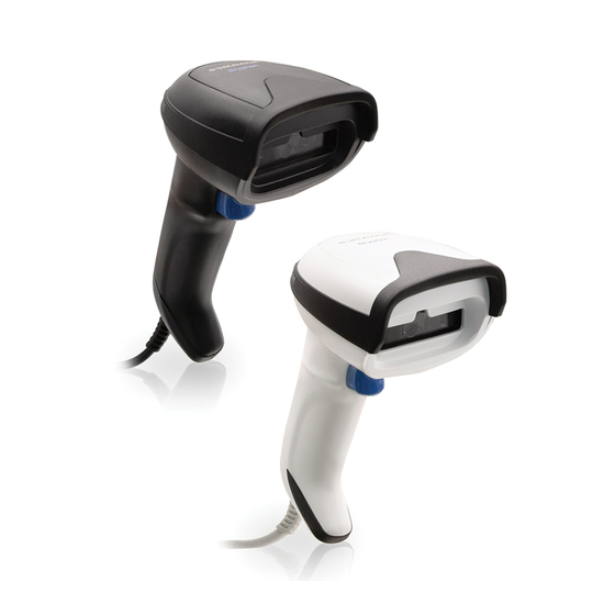
Datalogic Gryphon GD4200 Product Reference Manual
General purpose linear bar code reader: corded or with bluetooth wireless technology or datalogic’s star cordless system
Hide thumbs
Also See for Gryphon GD4200:
- Quick reference manual (44 pages) ,
- Quick reference manual (44 pages)

Related Manuals for Datalogic Gryphon GD4200


Summary of Contents for Datalogic Gryphon GD4200
- Page 1 Gryphon™ I GD/GBT/GM4200 PRODUCT REFERENCE GUIDE General Purpose Linear Bar Code Reader: Corded or with Bluetooth® Wireless Technology or Datalogic’s STAR Cordless System™...
- Page 2 Gryphon is a trademark of Datalogic S.p.A. and/or its affiliates, registered in the U.S. The Bluetooth word mark and logos are owned by Bluetooth SIG, Inc. and any use of such marks by Datalogic S.p.A. and/or its affiliates is under license. All other trademarks and brands are property of their respective owners.
-
Page 3: Table Of Contents
Replacing the Battery Pack ..................... 20 Using the Gryphon™ I GD/GBT/GM4200 ................21 Linear Bar ..........................22 Linking the Reader ......................22 Link Datalogic Devices to Base ......................22 Link Scanner as Serial Device to a Bluetooth Host .................22 PRODUCT REFERENCE GUIDE... - Page 4 Interface Selection ......................24 Configuring the Interface ....................24 Customizing Configuration Settings .................28 Using the Programming Bar Codes ....................28 Datalogic Aladdin™ Utility ........................ 28 Interface Settings ..........................28 Configuring Other Features ......................29 Software Version Transmission ....................... 29 Resetting the Product Configuration to Defaults ................29 Restore Custom Default Configuration ..................29...
- Page 5 USB-OEM Interface Options .....................77 IBM 46XX INTERFACE ....................78 IBM 46xx Interface Options .......................79 DATA FORMAT ......................80 Global Prefix/Suffix ........................81 Global AIM ID ..........................82 GS1-128 AIM ID .........................82 LABEL ID ............................83 Label ID: Pre-loaded Sets ......................83 Label ID: Set Individually Per Symbology ................84 Label ID Control ........................84 Label ID Symbology Selection ....................85 Case Conversion ........................90...
- Page 6 UPC-E Number System Character Transmission ..............116 GTIN Formatting ........................117 EAN-13 ............................118 EAN-13 Enable/Disable ......................118 EAN-13 Check Character Transmission ................118 EAN-13 Flag 1 Character ......................119 EAN-13 to ISBN Conversion ....................119 EAN-13 to ISSN Conversion ....................120 EAN-8 ..............................121 EAN-8 Enable/Disable ......................121 EAN-8 Check Character Transmission ..................121 Expand EAN-8 to EAN-13 ......................122 UPC/EAN GLOBAL SETTINGS ......................123 UPC/EAN Price Weight Check ....................123...
- Page 7 Compressed 2 of 5 Set Length 2 ....................155 DATALOGIC 2 OF 5 ..........................156 Datalogic 2 of 5 Enable/Disable ....................156 Datalogic 2 of 5 Check Character Calculation ................156 Datalogic 2 of 5 Check Character Transmission ..............157 Datalogic 2 of 5 Length Control ....................157 Datalogic 2 of 5 Set Length 1 ....................158...
- Page 8 ABC Codabar Dynamic Concatenation Timeout ..............171 ABC Codabar Force Concatenation ..................171 ISBT 128 ............................172 ISBT 128 Concatenation ......................172 ISBT 128 Concatenation Mode ....................172 ISBT 128 Dynamic Concatenation Timeout ................173 ISBT 128 Force Concatenation ....................174 ISBT 128 Advanced Concatenation Options ................174 CODE 11 ............................175 Code 11 Enable/Disable ......................175 Code 11 Check Character Calculation ..................175...
- Page 9 Copy Configuration to Base Station ..................201 BATCH FEATURES ...........................202 Batch Mode ..........................202 Send Batch ..........................202 Erase Batch Memory ......................203 RF Batch Mode Transmit Delay ....................203 DIRECT RADIO AUTOLINK ......................204 Direct Radio Autolink ......................204 RF ADDRESS STAMPING ........................205 Source Radio Address Transmission ..................205 Source Radio Address Delimiter Character ................205 BLUETOOTH-ONLY FEATURES ......................206 Bluetooth Security Level ......................206...
- Page 10 Good Read LED Duration ........................244 RF Features ......................... 245 Automatic Configuration Update ....................245 RF Address Stamping ........................245 Source Radio Address Delimiter Character ................245 STAR Radio Protocol Timeout ......................246 Symbologies ........................ 247 Set Length ............................247 Set Length 1 ..........................247 Set Length 2 ..........................248 CHAPTER 5.
-
Page 11: Preface
Programming can alternatively be performed using the Datalogic Aladdin™ Configura- tion application, which is available from the Datalogic website listed on the back cover of this manual. This multi-platform utility program allows device configuration using a PC. -
Page 12: Manual Conventions
PREFACE Manual Conventions The following conventions are used in this document: The symbols listed below are used in this manual to notify the reader of key issues or procedures that must be observed when using the reader: NOTE: This symbol draws attention to details or procedures that may be useful in improving, maintaining, or enhancing the performance of the hardware or software being discussed. -
Page 13: Technical Support
TECHNICAL SUPPORT Support Through the Website Datalogic provides several services as well as technical support through its website. Log on to (www.datalogic.com). For quick access, from the home page click on the search icon , and type in the name of the product you’re looking for. - Page 14 PREFACE NOTES GRYPHON™ I GD/GBT/GM4200...
-
Page 15: Chapter 1. Introduction
ABOUT THE SCANNER With rich feature sets and extensive model options, the Gryphon™ product series from Datalogic represents the premium level of data collection equipment for general pur- pose applications. The Gryphon I GD4200 readers’ ability to capture bar codes from near to far, to read... -
Page 16: Battery Safety
NOTE: Before installing the Battery, read “Battery Safety” on this and the following pages. Datalogic recommends annual replacement of recharge- able battery packs to ensure maximum performance. WARNING: Do not discharge the battery using any device except for the scanner. - Page 17 Use only the authorized power supplies, battery pack, chargers, and docks supplied by your Datalogic reseller. The use of any other power supplies can damage the device and void your warranty. Do not disassemble or modify the battery. The battery contains safety and protection devices, which, if damaged, may cause the battery to generate heat, explode or ignite.
-
Page 18: Programming The Reader
Aladdin also facilitates image capturing. In addition, Aladdin makes it easy to upgrade the handheld’s firmware, to attain the benefits of new reader features. Reference the Datalogic Aladdin™ Online Help for more details. Aladdin is available for download free of charge on the Datalogic website. -
Page 19: Chapter 2. Setup
CHAPTER 2 SETUP UNPACKING Check carefully to ensure the scanner and any cables or accessories ordered are present and undamaged. If any damage occurred during shipment, contact " Technical Support" on page xiii SETTING UP THE GRYPHON™ GD4200 READER Follow the steps provided in this section to connect and get your reader up and commu- nicating with its host: 1. -
Page 20: Rs-232 Serial Connection
SETUP Figure 2. Cable Connection/Disconnection at the Scanner Paper Clip Cable Connector RS-232 Serial Connection Turn off power to the terminal/PC and connect the scanner to the terminal/PC serial port via the RS-232 cable as shown in Figure 3. If the terminal will not support POT (Power Off the Terminal) to supply scanner power, use the approved power supply (AC Adapter). - Page 21 CONNECT HOST INTERFACE Figure 3 - Connection to the Host WEDGE RS-232 NOTE: Specific cables are required for connection to different hosts. The connections illustrated in Figure 3 are examples only. Actual connectors may vary from those illustrated, but the steps to connect the scanner remain the same.
-
Page 22: Stand Installation
SETUP STAND INSTALLATION Hands-Free Stand/Holder An accessory is available which holds the reader (except those with integrated stand) at a convenient angle, allowing hands free scanning of items. It can also be used as a holder. The holder “cup” can be positioned in any of the angles shown in the figure below. -
Page 23: Setting Up The Gryphon™ Gbt/Gm4200 Reader
* that battery packs of the stocked products GBT/GM42 and spare battery pack parts must be periodically recharged: for instance by using a WLC4190 or a WLC4090 cradle powered up with a 12V Datalogic AC/DC adapter (cod.8-0935) or a USB Type-C cable for at least 30 minutes each 3 months. -
Page 24: Positioning The Base Station
SETUP POSITIONING THE BASE STATION The base station/charger may be set up in desk application to hold the reader in two dif- ferent positions, either a horizontal or vertical position, in order to provide the most comfortable use depending on the needs. Base Station Positions and Related Clips to be Used Figure 5 - Horizontal Position This position is preferred, unless a different specific positioning is required, for its... - Page 25 POSITIONING THE BASE STATION Figure 6 - Vertical Position This position is preferred when lack of room on the desktop recommends the scanner to be left vertical during recharging. NOTE: For vertical installation, do not exceed two meters in height. PRODUCT REFERENCE GUIDE...
-
Page 26: Vertical Mount Adapter
SETUP Vertical Mount Adapter An accessory is available to be ordered separately (not supplied), for the vertical mount position. Figure 7 - Fixing the Adapter Pair the adapter to the base and then slide it upwards, as indicated by the arrows, to snap the adapter into the base. - Page 27 POSITIONING THE BASE STATION Figure 10 - Mounting Holes Dimensions Figure 11 - Overall Dimensions 94 mm [3.7 in] 203 mm 84 mm [8 in] [3.3 in] PRODUCT REFERENCE GUIDE...
-
Page 28: Reader, Cradle And Leds Description
SETUP READER, CRADLE AND LEDS DESCRIPTION provide information about the battery charging status as well as LEDs on the gun data transmission. Figure 12 - Gryphon 4200 Gun LEDs 1. Scan Window 3. Battery & Recharge LED 2. Trigger 4. Good Read LED Figure 13 - WLC4190 Base Station LEDs 1. -
Page 29: Connecting The Base Station
CONNECTING THE BASE STATION CONNECTING THE BASE STATION The following figure shows how to connect the Base Station to a terminal, PC or other host device. Turn off the host before connection and consult the manual for that equip- ment (if necessary) before proceeding. Connect the interface cable before applying power to the Base Station. -
Page 30: Securing The Cable (Optional)
SETUP Securing the Cable (Optional) The interface cable can be secured to the bottom of the base in order to maximize the mechanical retention of the cable itself. The routing of the cable can be changed to accommodate base station positioning: horizontal or vertical mount. The cable can be looped around to the front of the Base Station, or fed directly out the back of the Base Station, as shown in the figure below. -
Page 31: Disconnecting The Cable
Figure 17 - Disconnecting the Cable from WLC4190 NOTE: To detach the cable from the WLC4090 base station, please refer to the procedure illustrated in Gryphon I 4500 Family Product Reference Guide, available on www.datalogic.com. SYSTEM AND NETWORK LAYOUTS Stand Alone Layouts Figure 18 - Single Reader Layout GRYPHON™... - Page 32 SETUP Figure 19 - Multiple Reader Layout GRYPHON™ HOST CRADLE In stand alone systems, each cradle is connected to a single Host. Figure 20 - Multiple Stand Alone Layouts Many stand alone connections can operate in the same physical area without interfer- ence, provided all readers and cradles in the system have different addresses.
-
Page 33: Using The Gbt/Gm4200 Scanner
Amber fading = battery level 0 to 50% Red fading = pre.charge The capacitive touch button can be used to force device connection via the Datalogic Aladdin Software tool and for paging the scanner when it is activated. See also... -
Page 34: Replacing The Battery Pack
SETUP REPLACING THE BATTERY PACK NOTE: Before proceeding, read “Battery Safety” on page 2 . To ensure max- imum performance, Datalogic recommends the replacement of the rechargeable battery pack if you note either of the following conditions: • battery life drops below approximately 80% of the original life;... -
Page 35: Using The Gryphon™ I Gd/Gbt/Gm4200
USING THE GRYPHON™ I GD/GBT/GM4200 3. Insert the new battery in the same position. 4. Plug the battery cable into its connector. NOTE: When inserting the new battery into the handle, take care to position the battery and the connector as illustrated above. 5. -
Page 36: Linear Bar
Relative Size and Location of Green Spot LINKING THE READER Link Datalogic Devices to Base Before configuring the interface it is necessary to link the handheld with the base. To link the handheld and the base simply put it into the base. If the reader was previ- ously linked to another base, you must first scan the Unlink bar code before re-linking to the new base. -
Page 37: Link Scanner As Hid Device To A Bluetooth Host
BLUETOOTH PASSKEY OR PIN CODE ENTRY REQUEST Link to Host in SPP Mode Link Scanner as HID device to a Bluetooth host Use this procedure to send data to a Bluetooth host using the Bluetooth HID profile. 1. If using a Bluetooth adapter on the host device, install any driver provided with the adapter. -
Page 38: Power Off
• IBM46XX port 9b (a specific cable is required) • Datalogic Magellan Scanners' specific interface CONFIGURING THE INTERFACE Scan the programming bar code from the following section which selects the appropri- ate interface type to match the system the scanner will be connected to. Next, proceed to the corresponding chapter in this manual (also listed in the table) to configure any desired settings and features associated with that interface. - Page 39 Select RS-232 OPOS USB-COM USB-COM (simulates RS-232 standard interface) $P,HA47.P Select USB-COM-STD USB-Composite (combines USB-KBD emulation and USB-COM $P,HA4D.P Select USB-Composite a. USB-COM driver needs to be installed for these interfaces to work. Please download it from www.datalogic.com PRODUCT REFERENCE GUIDE...
- Page 40 Select USB HID POS USB Toshiba TEC $P,HA41.P Select USB Toshiba TEC Datalogic Magellan Scanners' specific interface, USB AUX $P,HA40.P Select Datalogic Magellan Scanners' USB AUX Datalogic Magellan RS232 AUX port $P,HA43.P Magellan RS232 AUX port USB-OEM USB-OEM (can be used for OPOS/UPOS/JavaPOS) $P,HA45.P...
- Page 41 CONFIGURING THE INTERFACE KEYBOARD AT, PS/2 25-286, 30-286, 50, 50Z, 60, 70, 80, 90 & 95 w/Standard Key Encoding $P,HA29.P Select KBD-AT Keyboard Wedge for IBM AT PS2 with standard key encoding but without external keyboard $P,HA11.P Select KBD-AT-NK AT, PS/2 25-286, 30-286, 50, 50Z, 60, 70, 80, 90 & 95 w/Alternate Key $P,HA26.P Select KBD-AT-ALT...
-
Page 42: Customizing Configuration Settings
Datalogic Aladdin™ Utility Programming can alternatively be performed using the Datalogic Aladdin™ Configura- tion application which is available for free download from the Datalogic website listed on the back cover of this manual. This multi-platform utility program allows device con- figuration using a PC. -
Page 43: Configuring Other Features
CUSTOMIZING CONFIGURATION SETTINGS Configuring Other Features If your installation requires different programming than the standard factory default settings, the following sections of this manual allow configuration of non-interface-spe- cific settings you might require: Configuration Using Bar Codes: General Features includes programming for scanning, speaker and LED indicators and other such universal settings. -
Page 44: Restore Factory Configuration
SETUP Restore Factory Configuration If you want to restore the Factory Configuration for your reader, scan either the Restore USA Factory Configuration bar code or the Restore EU Factory Configuration bar code below. Both labels restore the reader configuration to the factory settings, including the interface type. -
Page 45: Chapter 3. Configuration With Bar Codes
CHAPTER 3 CONFIGURATION WITH BAR CODES This and following sections provide programming bar codes to configure your reader by changing the default settings. For details about additional methods of programming, see " Customizing Configuration Settings" on page 28 NOTE: You must first enable your PowerScan to read bar codes in order to use this section. -
Page 46: Symbology-Specific Parameters
CONFIGURATION WITH BAR CODES Symbology-specific parameters: defines options for all symbologies and provides the Symbologies, starting on page 111 programming bar codes necessary for configuring these features. NOTE: You must first enable your reader to read bar codes in order to use this section. -
Page 47: Global Interface Features
GLOBAL INTERFACE FEATURES ENTER/EXIT PROGRAMMING MODE GLOBAL INTERFACE FEATURES The following interface features are configurable by all interface types. To set features specific to your interface, turn to that section of this manual. Host Commands — Obey/Ignore This option specifies whether the reader will obey or ignore host commands. When set to ignore, the reader will ignore all host commands except those necessary for: •... -
Page 48: Rs-232 Interface
CONFIGURATION | RS-232 INTERFACE Use the programming bar codes in this chapter if modifications to the standard RS-232 interface settings are necessary to meet your system’s requirements. Additional settings which apply to both the RS-232 and USB interfaces are available in RS-232/USB-COM Settings, starting on page 40 SECTION CONTENTS... -
Page 49: Rs-232 Standard Settings
RS-232 STANDARD SETTINGS ENTER/EXIT PROGRAMMING MODE RS-232 STANDARD SETTINGS Baud Rate Baud rate is the number of bits of data transmitted per second. Set the scanner's baud rate to match the baud rate setting of the host device. With an improper baud rate set- ting, data may not reach the host correctly. -
Page 50: Data Bits
ENTER/EXIT PROGRAMMING MODE RS-232 INTERFACE Data Bits This parameter allows the reader to interface with devices requiring a 7-bit or 8-bit ASCII protocol for sending and receiving data. $CR2DA00 7 Data Bits $CR2DA01 8 Data Bits NOTE: Handheld and Cradle models support the 8-bit ASCII protocol. The 7-bit ASCII protocol support is subject to specific firmware release. -
Page 51: Parity
RS-232 STANDARD SETTINGS ENTER/EXIT PROGRAMMING MODE Parity This feature specifies parity required for sending and receiving data. A parity check bit is the most significant bit of each ASCII coded character. Select the parity type according to host device requirements. •... -
Page 52: Handshaking Control
ENTER/EXIT PROGRAMMING MODE RS-232 INTERFACE Handshaking Control The data interface consists of an RS-232 port designed to operate either with or without the hardware handshaking lines, Request to Send (RTS), and Clear to Send (CTS). Hand- shaking Control includes the following options: •... -
Page 53: Rs-232/Usb-Com Interfaces
CONFIGURATION | RS-232/USB-COM INTERFACES SECTION CONTENTS • • Intercharacter Delay ACK NAK Timeout Value • • Beep On ASCII BEL ACK NAK Retry Count • • Beep On Not on File ACK NAK Error Handling • • ACK NAK Options Indicate Transmission Failure •... -
Page 54: Rs-232/Usb-Com Settings
ENTER/EXIT PROGRAMMING MODE RS-232/USB-COM INTERFACES RS-232/USB-COM SETTINGS Intercharacter Delay This parameter specifies the intercharacter delay between the end of one character and the beginning of the next. The delay can be set within a range of zero (0) to 990 millisec- onds in 10ms increments. -
Page 55: Beep On Ascii Bel
BEEP ON ASCII BEL ENTER/EXIT PROGRAMMING MODE Beep On ASCII BEL When this parameter is enabled, the scanner issues a beep when a <BEL> character is detected on the RS-232 serial line. <BEL> is issued to gain a user's attention to an illegal entry or other important event. -
Page 56: Ack Nak Options
ENTER/EXIT PROGRAMMING MODE RS-232/USB-COM INTERFACES ACK NAK Options This enables/disables the ability of the scanner to support the RS-232 ACK/NAK proto- col. When configured, the scanner and/or host sends an “ACK” when it receives data properly, and sends “NAK” when the data is in error. Options are: •... -
Page 57: Ack Character
ACK CHARACTER ENTER/EXIT PROGRAMMING MODE ACK Character This setting specifies an ASCII character or hex value to be used as the ACK character. ASCII characters or any hex value from 0 to 0xFF can be selected. See " ACK Character" on for more detailed programming instructions. -
Page 58: Ack Nak Timeout Value
ENTER/EXIT PROGRAMMING MODE RS-232/USB-COM INTERFACES ACK NAK Timeout Value This option specifies the amount of time the scanner waits for an ACK character from the host following label transmission. The selectable timeout range is 200 milliseconds to 15,000ms (15 seconds) in 200ms increments. A selection of 0 disables the timeout. -
Page 59: Ack Nak Error Handling
ACK NAK ERROR HANDLING ENTER/EXIT PROGRAMMING MODE ACK NAK Error Handling This feature specifies the method the scanner uses to handle receive errors detected while waiting for an ACK character from the host. Options are: • Ignore errors detected • Process error as valid ACK character •... -
Page 60: Disable Character
ENTER/EXIT PROGRAMMING MODE RS-232/USB-COM INTERFACES Disable Character Specifies the value of the RS-232 host command used to disable the scanner. ASCII characters or any hex value from 0 to 0xFF can be selected. See " Disable for more detailed programming instructions. Character"... -
Page 61: Keyboard Interface
CONFIGURATION | KEYBOARD INTERFACE SECTION CONTENTS OUNTRY starting on page 48 • Setting Country Mode THER EYBOARD ARAMETERS starting on page 63 • • Encoding Type Keyboard Send Control Characters • • ALT Output Type Wedge Quiet Interval • • Caps Lock State Intercharacter Delay •... -
Page 62: Country Mode
COUNTRY MODE This feature specifies the country/language supported by the keyboard. The Country Mode setting is ignored if the interface uses alternate key encoding. SETUP ON PC TO USE ALT UNIVERSAL 1. Open Registry Edit 2. Set EnableHexNumpad to 1 as follows: 3. -
Page 63: Setting Country Mode
COUNTRY MODE ENTER/EXIT PROGRAMMING MODE Setting Country Mode $CKBCO00 United States $CKBCO01 French International (Belgian French) $CKBCO02 United Kingdom $CKBCO03 Danish $CKBCO04 French (France) $CKBCO05 German $CKBCO06 Italian PRODUCT REFERENCE GUIDE... - Page 64 ENTER/EXIT PROGRAMMING MODE KEYBOARD INTERFACE Setting Country Mode (continued) $CKBCO07 Norwegian $CKBCO08 Portuguese (Portugal) $CKBCO09 Spanish $CKBCO0A Swedish $CKBCO0B Swiss French $CKBCO0C Japanese ASCII $CKBCO0D Hungarian GRYPHON™ I GD/GBT/GM4200...
- Page 65 COUNTRY MODE ENTER/EXIT PROGRAMMING MODE Setting Country Mode (continued) $CKBCO0E Czech $CKBCO0F SlovaK $CKBCO10 Romanian $CKBCO11 Croatian $CKBCO12 Polish_214 $CKBCO13 French Canadian Win7 $CKBCO14 Lithuanian PRODUCT REFERENCE GUIDE...
- Page 66 ENTER/EXIT PROGRAMMING MODE KEYBOARD INTERFACE Setting Country Mode (continued) $CKBCO17 Vietnamese $CKBCO18 Russian $CKBCO19 Arabic 101 $CKBCO1A Chinese ASCII $CKBCO1B Thai-Kedmanee $CKBCO1C Albanian $CKBCO1D Arabic 102 GRYPHON™ I GD/GBT/GM4200...
- Page 67 COUNTRY MODE ENTER/EXIT PROGRAMMING MODE Setting Country Mode (continued) $CKBCO1E Arabic 102 AZERTY $CKBCO1F Azeri Cyrillic $CKBCO20 Azeri Latin $CKBCO21 Belarusian $CKBCO22 Bosnian Cyrillic $CKBCO23 Bosnian Latin $CKBCO24 Bulgarian Cyrillic PRODUCT REFERENCE GUIDE...
- Page 68 ENTER/EXIT PROGRAMMING MODE KEYBOARD INTERFACE Setting Country Mode (continued) $CKBCO25 Bulgarian Latin $CKBCO26 Canadian French (Legacy) $CKBCO27 Canadian Multilingual $CKBCO28 Chinese (Simplified) $CKBCO29 Chinese (Traditional) $CKBCO2A Czech Programmers $CKBCO2B Czech QWERTY GRYPHON™ I GD/GBT/GM4200...
- Page 69 COUNTRY MODE ENTER/EXIT PROGRAMMING MODE Setting Country Mode (continued) $CKBCO2C Dutch Netherland $CKBCO2D Estonian $CKBCO2E Faeroese $CKBCO2F Finnish $CKBCO30 French (Canada) 2000/XP $CKBCO31 French (Canada) 95/98 $CKBCO32 Galician PRODUCT REFERENCE GUIDE...
- Page 70 ENTER/EXIT PROGRAMMING MODE KEYBOARD INTERFACE Setting Country Mode (continued) $CKBCO33 Greek $CKBCO34 Greek Latin $CKBCO35 Greek Polytonic $CKBCO36 Greek220 $CKBCO37 Greek220 Latin $CKBCO38 Greek319 $CKBCO39 Greek319 Latin GRYPHON™ I GD/GBT/GM4200...
- Page 71 COUNTRY MODE ENTER/EXIT PROGRAMMING MODE Setting Country Mode (continued) $CKBCO3A Hebrew Israel $CKBCO3B Hungarian_101KEY $CKBCO3C Icelandic $CKBCO3D Irish $CKBCO3E Italian_142 $CKBCO3F Japanese (Shift-JIS) $CKBCO40 Kazakh PRODUCT REFERENCE GUIDE...
- Page 72 ENTER/EXIT PROGRAMMING MODE KEYBOARD INTERFACE Setting Country Mode (continued) $CKBCO41 Korean (Hangul) $CKBCO42 Korean ASCII $CKBCO43 Kyrgyz Cyrillic $CKBCO44 Latin America $CKBCO45 Latvian $CKBCO46 Latvian QWERTY $CKBCO47 Lithuanian_IBM GRYPHON™ I GD/GBT/GM4200...
- Page 73 COUNTRY MODE ENTER/EXIT PROGRAMMING MODE Setting Country Mode (continued) $CKBCO48 Macedonian -FYROM $CKBCO49 Maltese_47KEY $CKBCO4A Mongolian-Cyrillic $CKBCO4B Polish Programmer $CKBCO4C Portuguese Brazil $CKBCO4D Portuguese Brazilian ABNT $CKBCO4E Portuguese Brazilian ABNT2 PRODUCT REFERENCE GUIDE...
- Page 74 ENTER/EXIT PROGRAMMING MODE KEYBOARD INTERFACE Setting Country Mode (continued) $CKBCO4F Romanian Legacy $CKBCO50 Romanian Programmer $CKBCO51 Romanian Standard $CKBCO52 Russian Typewriter $CKBCO53 Serbian Cyrillic $CKBCO54 Serbian Latin $CKBCO55 Slovak QWERTY GRYPHON™ I GD/GBT/GM4200...
- Page 75 COUNTRY MODE ENTER/EXIT PROGRAMMING MODE Setting Country Mode (continued) $CKBCO56 Slovenian $CKBCO57 Spanish Variation $CKBCO58 Swiss German $CKBCO59 Tatar $CKBCO5A Turkish F $CKBCO5B Turkish Q $CKBCO5C Ukrainian PRODUCT REFERENCE GUIDE...
- Page 76 ENTER/EXIT PROGRAMMING MODE KEYBOARD INTERFACE Setting Country Mode (continued) $CKBCO5D US Dvorak $CKBCO5E US Dvorak Left Hand $CKBCO5F US Dvorak Right Hand $CKBCO60 US English (Mac) $CKBCO61 US English (North American) $CKBCO62 US International $CKBCO63 Uzbek Cyrillic GRYPHON™ I GD/GBT/GM4200...
-
Page 77: Other Keyboard Parameters
OTHER KEYBOARD PARAMETERS ENTER/EXIT PROGRAMMING MODE OTHER KEYBOARD PARAMETERS Encoding Type $CENCO00 Encoding Type = Don’t Use Encoding $CENCO03 Encoding Type = UTF_8 $CENCO04 Encoding Type = Windows 874 $CENCO05 Encoding Type = Windows 932 $CENCO06 Encoding Type = Windows 936 $CENCO07 Encoding Type = Windows 949 $CENCO08... - Page 78 ENTER/EXIT PROGRAMMING MODE KEYBOARD INTERFACE Encoding Type (continued) $CENCO09 Encoding Type = Windows 1250 $CENCO0A Encoding Type = Windows 1251 $CENCO0B Encoding Type = Windows 1252 $CENCO0C Encoding Type = Windows 1253 $CENCO0D Encoding Type = Windows 1254 $CENCO0E Encoding Type = Windows 1255 $CENCO0F Encoding Type = Windows 1256 GRYPHON™...
- Page 79 OTHER KEYBOARD PARAMETERS ENTER/EXIT PROGRAMMING MODE Encoding Type (continued) $CENCO10 Encoding Type = Windows 1257 $CENCO11 Encoding Type = Windows 1258 $CENCO12 Encoding Type = Windows 20866 $CENCO31 Encoding Type = Windows 54936 $CENCO13 Encoding Type = ISO 8859-1 $CENCO14 Encoding Type = ISO 8859-2 $CENCO15 Encoding Type = ISO 8859-3...
- Page 80 ENTER/EXIT PROGRAMMING MODE KEYBOARD INTERFACE Encoding Type (continued) $CENCO16 Encoding Type = ISO 8859-4 $CENCO17 Encoding Type = ISO 8859-5 $CENCO18 Encoding Type = ISO 8859-6 $CENCO19 Encoding Type = ISO 8859-7 $CENCO1A Encoding Type = ISO 8859-8 $CENCO1B Encoding Type = ISO 8859-9 $CENCO1C Encoding Type = ISO 8859-10 GRYPHON™...
- Page 81 OTHER KEYBOARD PARAMETERS ENTER/EXIT PROGRAMMING MODE Encoding Type (continued) $CENCO1D Encoding Type = ISO 8859-11 $CENCO1E Encoding Type = ISO 8859-13 $CENCO1F Encoding Type = ISO 8859-14 $CENCO20 Encoding Type = ISO 8859-15 $CENCO21 Encoding Type = ISO 8859-16 $CENCO22 Encoding Type = MS-DOS 437 $CENCO23 Encoding Type = MS-DOS 737...
- Page 82 ENTER/EXIT PROGRAMMING MODE KEYBOARD INTERFACE Encoding Type (continued) $CENCO24 Encoding Type = MS-DOS 775 $CENCO25 Encoding Type = MS-DOS 850 $CENCO26 Encoding Type = MS-DOS 852 $CENCO27 Encoding Type = MS-DOS 855 $CENCO28 Encoding Type = MS-DOS 857 $CENCO29 Encoding Type = MS-DOS 860 $CENCO2A Encoding Type = MS-DOS 861 GRYPHON™...
- Page 83 OTHER KEYBOARD PARAMETERS ENTER/EXIT PROGRAMMING MODE Encoding Type (continued) $CENCO2B Encoding Type = MS-DOS 862 $CENCO2C Encoding Type = MS-DOS 863 $CENCO2D Encoding Type = MS-DOS 865 $CENCO2E Encoding Type = MS-DOS 866 $CENCO2F Encoding Type = MS-DOS 869 $CENCO30 Encoding Type = Mac CP10000 PRODUCT REFERENCE GUIDE...
-
Page 84: Alt Output Type
ENTER/EXIT PROGRAMMING MODE KEYBOARD INTERFACE ALT Output Type This option specifies the encode type of ALT Mode when the scanner sends Output Key- board Data in Alt Mode. (Be aware that the scanner may switch automatically between ALT mode & Normal Keyboard Scancode, to correctly display some characters that are not present in the current Keyboard Country). -
Page 85: Caps Lock State
OTHER KEYBOARD PARAMETERS ENTER/EXIT PROGRAMMING MODE Caps Lock State This option specifies the format in which the scanner sends character data. This applies to Keyboard Wedge interfaces. This does not apply when an alternate key encoding key- board is selected. This does not apply to USB Keyboard. $CKBCL00 ... -
Page 86: Keyboard Numeric Keypad
ENTER/EXIT PROGRAMMING MODE KEYBOARD INTERFACE Keyboard Numeric Keypad This feature specifies if numeric characters will be sent using the standard keys or the numeric keypad. $CKBKP00 Keyboard Numeric Keypad = Standard Keys $CKBKP01 Keyboard Numeric Keypad = Numeric Keypad Keyboard Send Control Characters This feature is used by the Keyboard Wedge and USB Keyboard interfaces. -
Page 87: Wedge Quiet Interval
OTHER KEYBOARD PARAMETERS ENTER/EXIT PROGRAMMING MODE Wedge Quiet Interval This option specifies the amount of time to look for keyboard activity before the scan- ner breaks the keyboard connection in order to transmit data to host. The selectable range for this feature is from 0 to 990ms in 10ms increments. See " Wedge Quiet Interval"... -
Page 88: Intercode Delay
ENTER/EXIT PROGRAMMING MODE KEYBOARD INTERFACE Intercode Delay Specifies the delay between labels transmitted to the host for this interface. The select- able range for this feature is from 0 to 99 seconds. See " Intercode Delay" on page 230 more detailed programming instructions To configure this feature, scan the ENTER/EXIT PRO- GRAMMING MODE bar code above, then the bar code at left followed by the digits from the Alphanu-... -
Page 89: Usb Keyboard Speed
OTHER KEYBOARD PARAMETERS ENTER/EXIT PROGRAMMING MODE USB Keyboard Speed This option specifies the USB poll rate for a USB Keyboard. NOTE: This feature applies ONLY to the USB Keyboard interface. $CKBSP01 USB Keyboard Speed = 1ms $CKBSP02 USB Keyboard Speed = 2ms $CKBSP03 USB Keyboard Speed = 3ms $CKBSP05... -
Page 90: Usb-Oem Interface
CONFIGURATION | USB-OEM INTERFACE SECTION CONTENTS • • USB-OEM Device Usage USB-OEM Interface Options GRYPHON™ I GD/GBT/GM4200... -
Page 91: Usb-Oem Device Usage
ENTER/EXIT PROGRAMMING MODE USB-OEM Device Usage The USB-OEM protocol allows for the scanner to be identified as one of two dif- ferent types of bar code scanners. Depending on what other scanners you may already have connected to a USB-OEM POS, you may need to change this setting to enable all devices to communicate. -
Page 92: Ibm 46Xx Interface
CONFIGURATION | IBM 46XX INTERFACE SECTION CONTENTS • IBM 46xx Interface Options GRYPHON™ I GD/GBT/GM4200... -
Page 93: Ibm 46Xx Interface Options
ENTER/EXIT PROGRAMMING MODE IBM 46xx Interface Options This setting provides for an interface specific control mechanism. Options are: • Obey — Obey Scanner Configuration Host Commands • Ignore — Ignore Scanner Configuration Host Commands $CIFO101 Interface Options = Obey Scanner Configuration Host Commands $CIFO102 Interface Options = Ignore Scanner Configuration... -
Page 94: Data Format
CONFIGURATION | DATA FORMAT SECTION CONTENTS • • Global Prefix/Suffix GS1-128 AIM ID • Global AIM ID ABEL starting on page 83 • • Label ID: Pre-loaded Sets Label ID Control • • Label ID: Set Individually Per Symbology Label ID Symbology Selection •... -
Page 95: Global Prefix/Suffix
ENTER/EXIT PROGRAMMING MODE Global Prefix/Suffix Up to 20 ASCII characters may be added as a prefix (in a position before the bar code data) and/or as a suffix (in a position following the bar code data). See " Global Prefix/ for more detailed programming instructions. -
Page 96: Global Aim Id
ENTER/EXIT PROGRAMMING MODE DATA FORMAT Global AIM ID NOTE: This feature enables/disables addition of AIM IDs for all symbology types. AIM label identifiers (as opposed to custom characters you select yourself as with label identifiers) can be included with scanned bar code data. See " Global AIM ID"... -
Page 97: Label Id
LABEL ID ENTER/EXIT PROGRAMMING MODE LABEL ID A Label ID is a customizable code of up to three ASCII characters (each can be one of hex 0x01-0xFF), used to identify a bar code (symbology) type. It can be appended previous to or following the transmitted bar code data depending upon how this option is enabled. -
Page 98: Label Id: Set Individually Per Symbology
ENTER/EXIT PROGRAMMING MODE DATA FORMAT Label ID: Set Individually Per Symbology This feature configures a Label ID individually for a single symbology. NOTE: This setting requires the scanning of bar codes from multiple sec- tions. See " Label ID: Set Individually Per Symbology" on page 236 for more detailed programming instructions. -
Page 99: Label Id Symbology Selection
LABEL ID ENTER/EXIT PROGRAMMING MODE Label ID Symbology Selection This option selects the symbology for which a Label ID is to be configured. See " Label ID: for full instructions. Set Individually Per Symbology" on page 236 Make a mistake? Scan the CANCEL bar code to abort and not save the entry string. - Page 100 ENTER/EXIT PROGRAMMING MODE DATA FORMAT Label ID Symbology Selection (continued) $C32ID Set EAN-13/P2 Label ID Character(s) $C35ID Set EAN-13/P5 Label ID Character(s) $CISID Set ISBN Label ID Character(s) $CINID Set ISSN Label ID Character(s) $C8BID Set EAN-8 Label ID Character(s) $C82ID Set EAN-8/P2 Label ID Character(s) $C85ID...
- Page 101 LABEL ID ENTER/EXIT PROGRAMMING MODE Label ID Symbology Selection (continued) $CXBID Set GS1 DataBar Expanded Label ID Character(s) $CLBID Set GS1 DataBar Limited Label ID Character(s) $CC3ID Set Code 39 Label ID Character(s) $CP3ID Set Code 32 Label ID Character(s) $CCCID Set Code 39 CIP Label ID Character(s) $CC8ID...
- Page 102 DATA FORMAT Label ID Symbology Selection (continued) $CHRID Set Interleaved 2 of 5 CIP HR Label ID Character(s) $CD2ID Datalogic 2 of 5 Label ID Character(s) $CS2D Standard 2 of 5 Label ID Character(s) $CU2ID Industrial 2 of 5 Label ID Character(s)
- Page 103 LABEL ID ENTER/EXIT PROGRAMMING MODE Label ID Symbology Selection (continued) $CC1ID Code 11 Label ID Character(s) $CMSID Label ID Character(s) $CPLID Plessey Label ID Character(s) $CALID Anker Plessey Label ID Character(s) PRODUCT REFERENCE GUIDE...
-
Page 104: Case Conversion
ENTER/EXIT PROGRAMMING MODE DATA FORMAT Case Conversion This feature allows conversion of the case of all alphabetic characters to upper or lower case. NOTE: Case conversion affects ONLY scanned bar code data, and does not affect Label ID, Prefix, Suffix, or other appended data. $CLFCA00 ... -
Page 105: Reading Parameters
CONFIGURATION | READING PARAMETERS SECTION CONTENTS CANNING EATURES starting on page 92 • • Scan Mode Stand /Base Detection Behavior • • Scanning Active Time Stand Mode/Object Detection Indication (Stand Mode Flash) • Flash On Time • Stand Mode/Object Detection Sensitivity •... -
Page 106: Scanning Features
ENTER/EXIT PROGRAMMING MODE READING PARAMETERS SCANNING FEATURES Scan Mode Selects the reader’s scan operating mode. See in “References” for descriptions. page 239 $CSNRM00 Scan Mode = Trigger Single $CSNRM01 Scan Mode = Trigger Hold Multiple $CSNRM02 Scan Mode = Trigger Pulse Multiple $CSNRM03 Scan Mode = Flashing $CSNRM04... -
Page 107: Scanning Active Time
SCANNING FEATURES ENTER/EXIT PROGRAMMING MODE Scanning Active Time This setting specifies the amount of time that the reader stays in scan ON state once the state is entered. The range for this setting is from 1 to 255 seconds in 1-second incre- ments. -
Page 108: Flash Off Time
ENTER/EXIT PROGRAMMING MODE READING PARAMETERS Flash Off Time This feature specifies the OFF time for the indicator LED while in Flash Mode. The select- able range is 100 to 9,900 milliseconds (0.1 to 9.9 seconds), in 100 millisecond incre- ments. See in “References”... - Page 109 SCANNING FEATURES ENTER/EXIT PROGRAMMING MODE Double Read Timeout (continued) $CSNDR32 Double Read Timeout = 0.5 Second $CSNDR3C Double Read Timeout = 0.6 Second $CSNDR46 Double Read Timeout = 0.7 Second $CSNDR50 Double Read Timeout = 0.8 Second $CSNDR5A Double Read Timeout = 0.9 Second $CSNDR64 Double Read Timeout = 1 Second PRODUCT REFERENCE GUIDE...
-
Page 110: Stand /Base Detection Behavior
ENTER/EXIT PROGRAMMING MODE READING PARAMETERS Stand /Base Detection Behavior Specifies the behavior of the reader when stationary in a stand. There are two condi- tions which cause the reader to switch to Stand Mode/Object Detection: • The reader is configured to switch to Stand Mode/Object Detection when station- ary. -
Page 111: Stand Mode/Object Detection Indication (Stand Mode Flash)
SCANNING FEATURES ENTER/EXIT PROGRAMMING MODE Stand Mode/Object Detection Indication (Stand Mode Flash) This operation is useful for indicating when the reader is in Stand Mode. If enabled, the blue indicator will blink when Stand Mode scanning is active. $CSMFL00 Stand Mode/Object Detection Indication = Disable $CSMFL01 Stand Mode/Object Detection Indication = Enable... -
Page 112: Stand Mode/Object Detection Illumination Off Time
ENTER/EXIT PROGRAMMING MODE READING PARAMETERS Stand Mode/Object Detection Illumination Off Time Specifies the amount of time reader illumination stays off after pulling the trigger when in Stand Mode/Object Detection. The configurable range is 01 to 32 by 01 in increments of 500ms (500ms to 16 seconds). -
Page 113: Beeper Control
BEEPER CONTROL ENTER/EXIT PROGRAMMING MODE BEEPER CONTROL Power On Alert Disables or enables the indication (from the Beeper) that the reader is receiving power. $CBPPU00 Power On Alert = Disable (No Audible Indication) $CBPPU01 Power On Alert = Power-up Beep Good Read Beep Type Specifies whether the good read beep has a mono or bitonal beep sound. -
Page 114: Good Read Beep Frequency
ENTER/EXIT PROGRAMMING MODE READING PARAMETERS Good Read Beep Frequency Adjusts the good read beep to sound at a selectable low, medium or high frequency, selectable from the list below. (Controls the beeper’s pitch/tone.) $CBPFR00 Good Read Beep Frequency = Low $CBPFR01 Good Read Beep Frequency = Medium $CBPFR02... -
Page 115: Good Read Beep Length
BEEPER CONTROL ENTER/EXIT PROGRAMMING MODE Good Read Beep Length $CBPLE06 Good Read Beep Length = 60 msec $CBPLE08 Good Read Beep Length = 80 msec $CBPLE0A Good Read Beep Length = 100 msec $CBPLE0C Good Read Beep Length = 120 msec $CBPLE0E Good Read Beep Length = 140 msec $CBPLE10... -
Page 116: Good Read Beep Volume
ENTER/EXIT PROGRAMMING MODE READING PARAMETERS Good Read Beep Volume Selects the beeper volume (loudness) upon a good read beep. There are three select- able volume levels. $CBPVO00 Good Read Beep Volume = Beeper Off $CBPVO01 Good Read Beep Volume = Low $CBPVO02 Good Read Beep Volume = Medium $CBPVO03... -
Page 117: Led Control
LED CONTROL ENTER/EXIT PROGRAMMING MODE LED CONTROL RGB Good Read Enable Specifies whether the RGB good read indicator is enabled or disabled. $CRBGE00 RGB Good Read = Disable $CRBGE01 RGB Good Read = Enable RGB Good Read Color Selects the good read LED color. $CRBCL00 RGB Good Read Color = RED $CRBCL01... -
Page 118: Good Read Led Duration
ENTER/EXIT PROGRAMMING MODE READING PARAMETERS Good Read LED Duration This feature specifies the amount of time that the Good Read LED remains on following a good read. The good read LED on time can be set within a range of 100 milliseconds to 25,500 milliseconds (0.1 to 25.5 seconds) in 100ms increments. -
Page 119: Good Read: When To Indicate
LED CONTROL ENTER/EXIT PROGRAMMING MODE Good Read: When to Indicate This feature specifies when the reader will provide indication (beep and/or flash its green LED) upon successfully reading a bar code. $CBPIN00 Indicate Good Read = After Decode $CBPIN01 Indicate Good Read = After Transmit $CBPIN02 Indicate Good Read =... -
Page 120: Green Spot Duration
ENTER/EXIT PROGRAMMING MODE READING PARAMETERS Green Spot Duration Specifies the duration of the good read pointer beam after a good read. $CLSSP00 Green Spot Duration = Disable (Green Spot is Off) $CLSSP01 Green Spot Duration = Short (300 msec) $CLSSP02 Green Spot Duration = Medium (500 msec) $CLSSP03... -
Page 121: Camera Control
CAMERA CONTROL ENTER/EXIT PROGRAMMING MODE CAMERA CONTROL Aiming Pointer Enables/disables the aiming pointer for all symbologies. $CTAAP00 Aiming Pointer = Disable $CTAAP01 Aiming Pointer = Enable $CTAAP02 Aiming Pointer = Green Spot PRODUCT REFERENCE GUIDE... -
Page 122: Motion Features
CONFIGURATION | MOTION FEATURES SECTION CONTENTS OTION EATURES starting on page 109 • • Motionless Timeout High Motion Immunity • • Motion Sensitivity Motion Aiming Control GRYPHON™ I GD/GBT/GM4200... -
Page 123: Motion Features
MOTION FEATURES ENTER/EXIT PROGRAMMING MODE MOTION FEATURES Motionless Timeout The period of time that must expire without detecting any motion, before the scanner is assumed to be in a motionless condition. The selectable setting is from 500 to 25,500 milliseconds in 100 millisecond increments. This option relates to such features as the Stand Mode/Object Detection scanning with respect to motion. -
Page 124: High Motion Immunity
ENTER/EXIT PROGRAMMING MODE MOTION FEATURES High Motion Immunity When set to triggerless scanning mode (e.g. Flashing, Always On, Stand Mode/Object Detection, etc.) the reading capabilities can be modified according to two main goals: • increased performance for rapidly moving barcodes - Enable High Motion Immunity: •increased performance for distant barcodes - Disable High Motion Immunity: Depending on specific environmental conditions, application requirements, or expected performance, choose the best solution. -
Page 125: Symbologies
CONFIGURATION | SYMBOLOGIES SECTION CONTENTS ISABLE YMBOLOGIES starting on page 112 GS1-128 • • OUPON ONTROL starting on page 112 starting on page 145 UPC-A 5 (I 2 • • NTERLEAVED starting on page 113 starting on page 145 UPC-E 5 CIP HR •... -
Page 126: Disable All Symbologies
DISABLE ALL SYMBOLOGIES Scan this label to disable all symbologies. Disable All Symbologies COUPON CONTROL This feature is used to control the method of processing coupon labels. Options are: • Allow all — allow all coupon bar codes to be decoded •... -
Page 127: Upc-A
UPC-A ENTER/EXIT PROGRAMMING MODE UPC-A The following options apply to the UPC-A symbology. UPC-A Enable/Disable When disabled, the scanner will not read UPC-A bar codes. $CABEN00 UPC-A = Disable $CABEN01 UPC-A = Enable UPC-A Check Character Transmission Enable this option to transmit the check character along with UPC-A bar code data. $CABCT00 UPC-A Check Character Transmission = Don’t Send $CABCT01... -
Page 128: Expand Upc-A To Ean-13
ENTER/EXIT PROGRAMMING MODE SYMBOLOGIES Expand UPC-A to EAN-13 Expands UPC-A data to the EAN-13 data format. Selecting this feature also changes the symbology ID to match those required for EAN-13. $CAB3B00 UPC-A to EAN-13 = Don’t Expand $CAB3B01 UPC-A to EAN-13 = Expand UPC-A Number System Character Transmission This feature enables/disables transmission of the UPC-A number system character. -
Page 129: Upc-E
UPC-E ENTER/EXIT PROGRAMMING MODE UPC-E The following options apply to the UPC-E symbology. UPC-E Enable/Disable When disabled, the scanner will not read UPC-E bar codes. $CEBEN00 UPC-E = Disable $CEBEN01 UPC-E = Enable UPC-E Check Character Transmission Enable this option to transmit the check character along with UPC-E bar code data. $CEBCT00 UPC-E Check Character Transmission = Don’t Send $CEBCT01... -
Page 130: Expand Upc-E To Ean-13
ENTER/EXIT PROGRAMMING MODE SYMBOLOGIES Expand UPC-E to EAN-13 Expands UPC-E data to the EAN-13 data format. Selecting this feature also changes the symbology ID to match those required for EAN-13. $CEB3B00 UPC-E to EAN-13 = Don’t Expand $CEB3B01 UPC-E to EAN-13 = Expand Expand UPC-E to UPC-A Expands UPC-E data to the UPC-A data format. -
Page 131: Gtin Formatting
UPC-E ENTER/EXIT PROGRAMMING MODE GTIN Formatting This feature enables/disables the ability to convert UPC-E, UPC-A, EAN-8, and EAN-13 labels into the GTIN 14-character format. $CGBEN00 GTIN Formatting = Disable $CGBEN01 GTIN Formatting = Enable PRODUCT REFERENCE GUIDE... -
Page 132: 118
ENTER/EXIT PROGRAMMING MODE SYMBOLOGIES EAN-13 The following options apply to the EAN-13 symbology. EAN-13 Enable/Disable When disabled, the scanner will not read EAN-13 bar codes. $C3BEN00 EAN-13 = Disable $C3BEN01 = Enable EAN-13 EAN-13 Check Character Transmission Enable this option to transmit the check character along with EAN-13 bar code data. $C3BCT00 EAN-13 Check Character Transmission = Don’t Send $C3BCT01... -
Page 133: Ean-13 Flag 1 Character
EAN-13 ENTER/EXIT PROGRAMMING MODE EAN-13 Flag 1 Character Enables/disables transmission of an EAN/JAN-13 Flag1 character. The Flag 1 character is the first character of the label $C3BF100 EAN-13 Flag 1 Char = Don’t transmit $C3BF101 EAN-13 Flag 1 Char = Transmit EAN-13 to ISBN Conversion This option enables/disables conversion of EAN-13/JAN-13 Bookland labels starting with 978 to ISBN labels. -
Page 134: Ean-13 To Issn Conversion
ENTER/EXIT PROGRAMMING MODE SYMBOLOGIES EAN-13 to ISSN Conversion Enables/disables conversion of EAN/JAN-13 Bookland labels starting with 977 to ISSN labels. $C3BIN00 ISSN = Disable $C3BIN01 ISSN = Enable GRYPHON™ I GD/GBT/GM4200... -
Page 135: 121
EAN-8 ENTER/EXIT PROGRAMMING MODE EAN-8 The following options apply to the EAN-8 symbology. EAN-8 Enable/Disable When disabled, the scanner will not read EAN-8 bar codes. $C8BEN00 EAN-8 = Disable $C8BEN01 = Enable EAN-8 EAN-8 Check Character Transmission Enable this option to transmit the check character along with EAN-8 bar code data. $C8BCT00 EAN-8 Check Character Transmission = Don’t Send $C8BCT01... -
Page 136: Expand Ean-8 To Ean-13
ENTER/EXIT PROGRAMMING MODE SYMBOLOGIES Expand EAN-8 to EAN-13 Enable this option to expand EAN-8/JAN-8 labels to EAN-13/JAN-13. $C8B3B00 EAN-8 to EAN-13 = Don’t Expand $C8B3B01 EAN-8 to EAN-13 = Expand GRYPHON™ I GD/GBT/GM4200... -
Page 137: Upc/Ean Global Settings
UPC/EAN GLOBAL SETTINGS ENTER/EXIT PROGRAMMING MODE UPC/EAN GLOBAL SETTINGS This section provides configuration settings for UPC-A, UPC-E, EAN 13 and EAN 8 sym- bologies, and affects all of these unless otherwise marked for each feature description. UPC/EAN Price Weight Check This feature enables/disables calculation and verification of price/weight check digits. -
Page 138: Upc/Ean Quiet Zones
ENTER/EXIT PROGRAMMING MODE SYMBOLOGIES UPC/EAN Quiet Zones This feature specifies the number of quiet zones for UPC/EAN labels. Quiet zones are blank areas at the ends of a bar code, typically 10 times the width of the narrowest bar or space in the label. The property applies to all EAN-UPC symbologies globally and to the ADD-ONs. -
Page 139: Optional Add-Ons
UPC/EAN GLOBAL SETTINGS ENTER/EXIT PROGRAMMING MODE Optional Add-ons The scanner can be enabled to optionally read the following add-ons (supplementals): • • NOTE: If a UPC/EAN base label and a an add-on are both decoded, the scan- ner will transmit the base label and add-on. If a UPC/EAN base label is decoded without an add-on, the base label will be transmitted without an add-on. -
Page 140: Optional Add-On Timer
ENTER/EXIT PROGRAMMING MODE SYMBOLOGIES Optional Add-On Timer This option sets the time the scanner will look for an add-on when an add-on fragment has been seen and optional add-ons are enabled. $CADOT01 Optional Add-on Timer = 10ms $CADOT02 Optional Add-on Timer = 20ms $CADOT03 Optional Add-on Timer = 30ms $CADOT05... -
Page 141: Gs1 Databar™ Omnidirectional
GS1 DATABAR™ OMNIDIRECTIONAL ENTER/EXIT PROGRAMMING MODE GS1 DATABAR™ OMNIDIRECTIONAL The following options apply to the GS1 DataBar Omnidirectional (formerly RSS-14) sym- bology. GS1 DataBar Omnidirectional Enable/Disable When disabled, the scanner will not read GS1 DataBar Omnidirectional bar codes. $C4BEN00 GS1 DataBar Omnidirectional = Disable $C4BEN01 GS1 DataBar Omnidirectional = Enable... -
Page 142: Gs1 Databar™ Expanded
ENTER/EXIT PROGRAMMING MODE SYMBOLOGIES GS1 DATABAR™ EXPANDED The following options apply to the GS1 DataBar Expanded (formerly RSS Expanded) sym- bology. GS1 DataBar Expanded Enable/Disable When disabled, the scanner will not read GS1 DataBar Expanded bar codes. $CXBEN00 GS1 DataBar Expanded = Disable $CXBEN01 GS1 DataBar Expanded = Enable GS1 DataBar Expanded to GS1-128 Emulation... -
Page 143: Gs1 Databar Expanded Length Control
GS1 DATABAR™ EXPANDED ENTER/EXIT PROGRAMMING MODE GS1 DataBar Expanded Length Control This feature specifies either variable length decoding or fixed length decoding for the GS1 DataBar Expanded symbology. For variable-length decoding, a minimum length may be set. Variable Length: For fixed-length decoding, two different lengths may be set. Fixed Length: $CXBLC00 ... -
Page 144: Gs1 Databar Expanded Set Length 2
ENTER/EXIT PROGRAMMING MODE SYMBOLOGIES GS1 DataBar Expanded Set Length 2 This feature specifies one of the bar code lengths for " GS1 DataBar Expanded Length . Length 2 is the maximum label length if in Variable Length Mode, Control" on page 129 or the second fixed length if in Fixed Length Mode. -
Page 145: Gs1 Databar™ Limited
GS1 DATABAR™ LIMITED ENTER/EXIT PROGRAMMING MODE GS1 DATABAR™ LIMITED The following options apply to the GS1 DataBar Limited (formerly RSS Limited) symbol- ogy. GS1 DataBar Limited Enable/Disable When disabled, the scanner will not read GS1 DataBar Limited bar codes. $CLBEN00 ... -
Page 146: Code 39
ENTER/EXIT PROGRAMMING MODE SYMBOLOGIES CODE 39 The following options apply to the Code 39 symbology. Code 39 Enable/Disable When disabled, the scanner will not read Code 39 bar codes. $CC3EN00 Code 39 = Disable $CC3EN01 Code 39 = Enable Code 39 Check Character Calculation Enable this option to enable/disable calculation and verification of an optional Code 39 check character. -
Page 147: Code 39 Check Character Transmission
CODE 39 ENTER/EXIT PROGRAMMING MODE $CC3CC08 Code 39 Check Character Calculation = Enable Daimler Chrysler Check Code 39 Check Character Transmission Enable this option to transmit the check character along with Code 39 bar code data. $CC3CT00 Code 39 Check Character Transmission = Don’t Send $CC3CT01 ... -
Page 148: Code 39 Full Ascii
ENTER/EXIT PROGRAMMING MODE SYMBOLOGIES Code 39 Full ASCII In Code 39 decoding, this enables/disables the translation of Code 39 characters to Code 39 full-ASCII characters. $CC3FA00 Code 39 Full ASCII = Disable $CC3FA01 Code 39 Full ASCII = Enable Code 39 Quiet Zones This feature specifies the number of quiet zones for Code 39 labels. -
Page 149: Code 39 Length Control
CODE 39 ENTER/EXIT PROGRAMMING MODE Code 39 Length Control This feature specifies either variable length decoding or fixed length decoding for the Code 39 symbology. For variable-length decoding, a minimum length may be set. Variable Length: For fixed-length decoding, two different lengths may be set. Fixed Length: $CC3LC00 ... -
Page 150: Code 39 Set Length 2
ENTER/EXIT PROGRAMMING MODE SYMBOLOGIES Code 39 Set Length 2 This feature specifies one of the bar code lengths for " Code 39 Length Control" on page . Length 2 is the maximum label length if in Variable Length Mode, or the second fixed length if in Fixed Length Mode. -
Page 151: Trioptic Code
TRIOPTIC CODE ENTER/EXIT PROGRAMMING MODE TRIOPTIC CODE The following options apply to the trioptic symbology. Trioptic Code Enable/Disable When disabled, the scanner will not read Trioptic Code bar codes. $CCTEN00 Trioptic Code = Disable $CCTEN01 Trioptic Code = Enable CODE 39 DANISH PPT The following options apply to the Code 39 Danish PPT symbology. -
Page 152: Code 39 Pzn
ENTER/EXIT PROGRAMMING MODE SYMBOLOGIES CODE 39 PZN The following options apply to the Code 39 PZN symbology. Code 39 PZN Enable/Disable When disabled, the scanner will not read Code 39 PZN bar codes. $CPZEN00 Code 39 PZN = Disable $CPZEN01 Code 39 PZN = Enable CODE 39 LA POSTE... -
Page 153: Code 32 (Italian Pharmaceutical)
CODE 32 (ITALIAN PHARMACEUTICAL) ENTER/EXIT PROGRAMMING MODE CODE 32 (ITALIAN PHARMACEUTICAL) The following options apply to the Code 32 symbology. Code 32 Enable/Disable When disabled, the scanner will not read Code 32 bar codes. $CP3EN00 Code 32 = Disable $CP3EN01 Code 32 = Enable Code 32 Feature Setting Exceptions... -
Page 154: Code 32 Start/Stop Character Transmission
ENTER/EXIT PROGRAMMING MODE SYMBOLOGIES Code 32 Start/Stop Character Transmission Enable this option to enable/disable transmission of Code 32 start and stop characters. $CP3SS00 Code 32 Start/Stop Character Transmission = Don’t Transmit $CP3SS01 Code 32 Start/Stop Character Transmission = Transmit CODE 39 CIP (FRENCH PHARMACEUTICAL) The following options apply to the Code 39 CIP symbology. -
Page 155: Code 128
CODE 128 ENTER/EXIT PROGRAMMING MODE CODE 128 The following options apply to the Code 128 symbology. Code 128 Enable/Disable Enables/Disables ability of the scanner to decode Code 128 labels. $CC8EN00 Code 128 = Disable $CC8EN01 Code 128 = Enable Expand Code 128 to Code 39 This feature enables/disables expansion of Code 128 labels to Code 39 labels. -
Page 156: Code 128 Check Character Transmission
ENTER/EXIT PROGRAMMING MODE SYMBOLOGIES Code 128 Check Character Transmission Enable this option to transmit the check character along with Code 128 bar code data. $CC8CT00 Code 128 Check Character Transmission = Don’t Send $CC8CT01 Code 128 Check Character Transmission = Send Code 128 Function Character Transmission Enables/disables transmission of Code128 function characters 1, 2, 3, and 4. -
Page 157: Code 128 Quiet Zones
CODE 128 ENTER/EXIT PROGRAMMING MODE Code 128 Quiet Zones This feature specifies the number of quiet zones for Code 128 labels. Quiet zones are blank areas at the ends of a bar code and are typically 10 times the width of the narrow- est bar or space in the label. -
Page 158: Code 128 Set Length 1
ENTER/EXIT PROGRAMMING MODE SYMBOLOGIES Code 128 Set Length 1 This feature specifies one of the bar code lengths for " Code 128 Length Control" on page . Length 1 is the minimum label length if in Variable Length Mode, or the first fixed length if in Fixed Length Mode. -
Page 159: Gs1-128
GS1-128 ENTER/EXIT PROGRAMMING MODE GS1-128 The following options apply to the GS1-128 symbology. (Also known as USS-128, GTIN- 128, UCC-128.) GS1-128 Enable This option enables/disables the ability of the scanner to translate GS1-128 labels to the GS1-128 data format. Options are: •... -
Page 160: I 2 Of 5 Enable/Disable
ENTER/EXIT PROGRAMMING MODE SYMBOLOGIES I 2 of 5 Enable/Disable When disabled, the scanner will not read I 2 of 5 bar codes. $CI2EN00 I 2 of 5 = Disable $CI2EN01 I 2 of 5 = Enable I 2 of 5 Check Character Calculation This option enables/disables calculation and verification of an optional I 2 of 5 check character. -
Page 161: I 2 Of 5 Check Character Transmission
INTERLEAVED 2 OF 5 (I 2 OF 5) ENTER/EXIT PROGRAMMING MODE I 2 of 5 Check Character Calculation (continued) $CI2CC10 I 2 of 5 Check Character Calculation = Calculate Bosch Check $CI2CC20 I 2 of 5 Check Character Calculation = Calculate Italian Post Check I 2 of 5 Check Character Transmission Enable this option to transmit the check character along with I 2 of 5 bar code data. -
Page 162: I 2 Of 5 Length Control
ENTER/EXIT PROGRAMMING MODE SYMBOLOGIES I 2 of 5 Length Control This feature specifies either variable length decoding or fixed length decoding for the I 2 of 5 symbology. For variable-length decoding, a minimum length may be set. Variable Length: For fixed-length decoding, two different lengths may be set. Fixed Length: $CI2LC00 ... -
Page 163: I 2 Of 5 Set Length 2
INTERLEAVED 2 OF 5 CIP HR ENTER/EXIT PROGRAMMING MODE I 2 of 5 Set Length 2 This feature specifies one of the bar code lengths for " I 2 of 5 Length Control" on page . Length 2 is the maximum label length if in Variable Length Mode, or the second fixed length if in Fixed Length Mode. -
Page 164: Standard 2 Of 5
ENTER/EXIT PROGRAMMING MODE SYMBOLOGIES STANDARD 2 OF 5 The following options apply to the Standard 2 of 5 symbology. Standard 2 of 5 Enable/Disable When disabled, the scanner will not read Standard 2 of 5 bar codes. $CS2EN00 Standard 2 of 5 = Disable $CS2EN01 Standard 2 of 5 = Enable Standard 2 of 5 Check Character Calculation... -
Page 165: Standard 2 Of 5 Check Character Transmission
STANDARD 2 OF 5 ENTER/EXIT PROGRAMMING MODE Standard 2 of 5 Check Character Transmission This feature enables/disables transmission of an optional Standard 2 of 5 check charac- ter. $CS2CT00 Standard 2 of 5 Check Character Transmission = Don’t Send $CS2CT01 ... -
Page 166: Standard 2 Of 5 Set Length 1
ENTER/EXIT PROGRAMMING MODE SYMBOLOGIES Standard 2 of 5 Set Length 1 This feature specifies one of the bar code lengths for " Standard 2 of 5 Length Control" on . Length 1 is the minimum label length if in Variable Length Mode, or the first page 151 fixed length if in Fixed Length Mode. -
Page 167: Compressed 2 Of 5
COMPRESSED 2 OF 5 ENTER/EXIT PROGRAMMING MODE COMPRESSED 2 OF 5 The following options apply to the Compressed 2 of 5 symbology. Compressed 2 of 5 Enable/Disable When disabled, the scanner will not read Compressed 2 of 5 bar codes. $CC2EN00 ... -
Page 168: Compressed 2 Of 5 Check Character Transmission
ENTER/EXIT PROGRAMMING MODE SYMBOLOGIES Compressed 2 of 5 Check Character Transmission This feature enables/disables transmission of an optional Compressed 2 of 5 check char- acter. $CC2CT00 Compressed 2 of 5 Check Character Transmission = Don’t Send $CC2CT01 Compressed 2 of 5 Check Character Transmission = Send Compressed 2 of 5 Length Control This feature specifies either variable length decoding or fixed length decoding for the... -
Page 169: Compressed 2 Of 5 Set Length 1
COMPRESSED 2 OF 5 ENTER/EXIT PROGRAMMING MODE Compressed 2 of 5 Set Length 1 This feature specifies one of the bar code lengths for " Compressed 2 of 5 Length Control" . Length 1 is the minimum label length if in Variable Length Mode, or the on page 154 first fixed length if in Fixed Length Mode. -
Page 170: Datalogic 2 Of 5
DATALOGIC 2 OF 5 The following options apply to the Datalogic 2 of 5 symbology. Datalogic 2 of 5 Enable/Disable When disabled, the scanner will not read Datalogic 2 of 5 bar codes. $CD2EN00 Datalogic 2 of 5 = Disable... -
Page 171: Datalogic 2 Of 5 Check Character Transmission
DATALOGIC 2 OF 5 ENTER/EXIT PROGRAMMING MODE Datalogic 2 of 5 Check Character Transmission Enable this option to transmit the check character along with Datalogic 2 of 5 bar code data. $CD2CT00 Datalogic 2 of 5 Check Character Transmission = Don’t Send $CD2CT01 ... -
Page 172: Datalogic 2 Of 5 Set Length 1
Alphanu- meric characters in Appendix D, Keypad represent- Select Datalogic 2 of 5 Set Length 2 Setting ing your desired character(s). End by scanning the $CD2L2 ENTER/EXIT bar code again. Make a mistake? Scan the CANCEL bar code to abort and not save the entry string. -
Page 173: Industrial 2 Of 5
INDUSTRIAL 2 OF 5 ENTER/EXIT PROGRAMMING MODE INDUSTRIAL 2 OF 5 The following options apply to the Industrial 2 of 5 symbology. Industrial 2 of 5 Enable/Disable When disabled, the scanner will not read Industrial 2 of 5 bar codes. $CU2EN00 ... -
Page 174: Industrial 2 Of 5 Check Character Transmission
ENTER/EXIT PROGRAMMING MODE SYMBOLOGIES Industrial 2 of 5 Check Character Transmission Enables/disables transmission of an Industrial 2 of 5 check character. $CU2CT00 Industrial 2 of 5 Check Character Transmission = Don’t Send $CU2CT01 Industrial 2 of 5 Check Character Transmission = Send Industrial 2 of 5 Length Control This feature specifies either variable length decoding or fixed length decoding for the... -
Page 175: Industrial 2 Of 5 Set Length 1
INDUSTRIAL 2 OF 5 ENTER/EXIT PROGRAMMING MODE Industrial 2 of 5 Set Length 1 This feature specifies one of the bar code lengths for " Industrial 2 of 5 Length Control" on . Length 1 is the minimum label length if in Variable Length Mode, or the first page 160 fixed length if in Fixed Length Mode. -
Page 176: Iata
ENTER/EXIT PROGRAMMING MODE SYMBOLOGIES IATA The following options apply to the IATA symbology. IATA Enable/Disable Enables/Disables the ability of the scanner to decode IATA labels. $CIAEN00 IATA = Disable $CIAEN01 IATA = Enable IATA Check Character Transmission Enables/Disables calculation and verification of an optional IATA check character. $CIACT00 IATA Check Character Transmission = Don’t Send... -
Page 177: Follett 2 Of 5
FOLLETT 2 OF 5 ENTER/EXIT PROGRAMMING MODE FOLLETT 2 OF 5 The following options apply to the Follett 2 of 5 symbology. Follett 2 of 5 Enable/Disable Enables/Disables ability of scanner to decode Follett 2 of 5 labels. $CF2EN00 Follett 2 of 5 = Disable $CF2EN01 Follett 2 of 5 = Enable... -
Page 178: Codabar
ENTER/EXIT PROGRAMMING MODE SYMBOLOGIES CODABAR The following options apply to the Codabar symbology. Codabar Enable/Disable When disabled, the scanner will not read Codabar bar codes. $CCBEN00 Codabar = Disable $CCBEN01 Codabar = Enable Codabar Check Character Calculation This option enables/disables calculation and verification of an optional Codabar check character. -
Page 179: Codabar Check Character Transmission
CODABAR ENTER/EXIT PROGRAMMING MODE Codabar Check Character Transmission Enable this option to transmit the check character along with Codabar bar code data. NOTE: This feature is valid only when Codabar Check Character Calculation is enabled. $CCBCT00 Codabar Check Character Transmission = Don’t Send $CCBCT01 ... -
Page 180: Codabar Start/Stop Character Set
ENTER/EXIT PROGRAMMING MODE SYMBOLOGIES Codabar Start/Stop Character Set This option specifies the format of transmitted Codabar start/stop characters. $CCBSC00 Codabar Check Character Set = ABCD/TN*E $CCBSC01 Codabar Check Character Set = ABCD/ABCD $CCBSC02 Codabar Check Character Set = abcd/tn*e $CCBSC03 ... -
Page 181: Codabar Quiet Zones
CODABAR ENTER/EXIT PROGRAMMING MODE Codabar Quiet Zones This feature specifies the number of quiet zones for Codabar labels. Quiet zones are blank areas at the ends of a bar code and are typically 10 times the width of the narrow- est bar or space in the label. -
Page 182: Codabar Length Control
ENTER/EXIT PROGRAMMING MODE SYMBOLOGIES Codabar Length Control This feature specifies either variable length decoding or fixed length decoding for the Codabar symbology. For variable-length decoding, a minimum length may be set. Variable Length: For fixed-length decoding, two different lengths may be set. Fixed Length: $CCBLC00 ... -
Page 183: Codabar Set Length 2
CODABAR ENTER/EXIT PROGRAMMING MODE Codabar Set Length 2 This feature specifies one of the bar code lengths for " Codabar Length Control" on page . Length 2 is the maximum label length if in Variable Length Mode, or the second fixed length if in Fixed Length Mode. -
Page 184: Abc Codabar
ENTER/EXIT PROGRAMMING MODE SYMBOLOGIES ABC CODABAR The following options apply to the ABC Codabar symbology. ABC Codabar Enable/Disable Enables/Disables ability of scanner to decode ABC Codabar labels. $CCBAB00 ABC Codabar = Disable $CCBAB01 ABC Codabar = Enable ABC Codabar Concatenation Mode Specifies the concatenation mode between Static and Dynamic. -
Page 185: Abc Codabar Dynamic Concatenation Timeout
ABC CODABAR ENTER/EXIT PROGRAMMING MODE ABC Codabar Dynamic Concatenation Timeout This parameter specifies the timeout in 10-millisecond ticks used by the ABC Codabar Dynamic Concatenation Mode. The timeout can be set within a range of 05 to 255 in 10ms increments. A setting of zero specifies no delay. To configure this feature, scan the ENTER/EXIT PRO- GRAMMING MODE bar code above, then the bar code at left followed by the digits from the Alphanu-... -
Page 186: Isbt 128
ENTER/EXIT PROGRAMMING MODE SYMBOLOGIES ISBT 128 The following options apply to the ISBT 128 symbology. ISBT 128 Concatenation Enables/disables ISBT 128 concatenation of 2 labels. $CI8CE00 ISBT 128 Concatenation = Disable $CI8CE01 ISBT 128 Concatenation = Enable ISBT 128 Concatenation Mode Specifies the concatenation mode between Static and Dynamic. -
Page 187: Isbt 128 Dynamic Concatenation Timeout
ISBT 128 ENTER/EXIT PROGRAMMING MODE ISBT 128 Dynamic Concatenation Timeout Specifies the timeout used by the ISBT 128 Dynamic Concatenation Mode. $CI8DT05 ISBT 128 Dynamic Concatenation Timeout = 50 msec $CI8DT0A ISBT 128 Dynamic Concatenation Timeout = 100 msec $CI8DT14 ... -
Page 188: Isbt 128 Force Concatenation
ISBT 128 Force Contatenation = Disable $CI8FC01 ISBT 128 Force Concatenation = Enable ISBT 128 Advanced Concatenation Options NOTE: Use the Datalogic Aladdin configuration application or Contact Cus- tomer Support to set up pairs of label types for concatenation. GRYPHON™ I GD/GBT/GM4200... -
Page 189: Code 11
CODE 11 ENTER/EXIT PROGRAMMING MODE CODE 11 The following options apply to the Code 11 symbology. Code 11 Enable/Disable When disabled, the scanner will not read Code 11 bar codes. $CC1EN00 Code 11 = Disable $CC1EN01 Code 11 = Enable Code 11 Check Character Calculation This option enables/disables calculation and verification of optional Code 11 check character. -
Page 190: Code 11 Check Character Transmission
ENTER/EXIT PROGRAMMING MODE SYMBOLOGIES Code 11 Check Character Transmission This feature enables/disables transmission of an optional Code 11 check character. $CC1CT00 Code 11 Check Character Transmission = Don’t Send $CC1CT01 Code 11 Check Character Transmission = Send Code 11 Length Control This feature specifies either variable length decoding or fixed length decoding for the Code 11 symbology. -
Page 191: Code 11 Set Length 1
CODE 11 ENTER/EXIT PROGRAMMING MODE Code 11 Set Length 1 This feature specifies one of the bar code lengths for " Code 11 Length Control" on page . Length 1 is the minimum label length if in Variable Length Mode, or the first fixed length if in Fixed Length Mode. -
Page 192: Code 93
ENTER/EXIT PROGRAMMING MODE SYMBOLOGIES CODE 93 The following options apply to the Code 93 symbology. Code 93 Enable/Disable Enables/Disables ability of scanner to decode Code 93 labels. $CC9EN00 Code 93 = Disable $CC9EN01 Code 93 = Enable Code 93 Check Character Calculation This option enables/disables calculation and verification of optional Code 93 check character. -
Page 193: Code 93 Check Character Transmission
CODE 93 ENTER/EXIT PROGRAMMING MODE Code 93 Check Character Transmission This feature enables/disables transmission of an optional Code 93 check character. $CC9CT00 Code 93 Check Character Transmission = Don’t Send $CC9CT01 Code 93 Check Character Transmission = Send Code 93 Length Control This feature specifies either variable length decoding or fixed length decoding for the Code 93 symbology. -
Page 194: Code 93 Set Length 1
ENTER/EXIT PROGRAMMING MODE SYMBOLOGIES Code 93 Set Length 1 This feature specifies one of the bar code lengths for " Code 93 Length Control" on page . Length 1 is the minimum label length if in Variable Length Mode, or the first fixed length if in Fixed Length Mode. -
Page 195: Code 93 Quiet Zones
CODE 93 ENTER/EXIT PROGRAMMING MODE Code 93 Quiet Zones This feature specifies the number of quiet zones for Code 93 labels. Quiet zones are blank areas at the ends of a bar code and are typically 10 times the width of the narrow- est bar or space in the label. -
Page 196: Msi
ENTER/EXIT PROGRAMMING MODE SYMBOLOGIES The following options apply to the MSI symbology. MSI Enable/Disable Enables/Disables ability of scanner to decode MSI labels. $CMSEN00 MSI = Disable $CMSEN01 MSI = Enable MSI Check Character Calculation Enables/Disables calculation and verification of an optional MSI check character. $CMSCC00 MSI Check Character Calculation = Disable $CMSCC01... -
Page 197: Msi Check Character Transmission
ENTER/EXIT PROGRAMMING MODE MSI Check Character Transmission Enables/disables transmission of an MSI check character. $CMSCT00 MSI Check Character Transmission = Don’t Send $CMSCT01 MSI Check Character Transmission = Send MSI Length Control This feature specifies either variable length decoding or fixed length decoding for the MSI symbology. -
Page 198: Msi Set Length 1
ENTER/EXIT PROGRAMMING MODE SYMBOLOGIES MSI Set Length 1 This feature specifies one of the bar code lengths for " MSI Length Control" on page 183 Length 1 is the minimum label length if in Variable Length Mode, or the first fixed length if in Fixed Length Mode. -
Page 199: Plessey
PLESSEY ENTER/EXIT PROGRAMMING MODE PLESSEY The following options apply to the Plessey symbology. Plessey Enable/Disable Enables/Disables ability of scanner to decode Plessey labels. $CPLEN00 Plessey = Disable $CPLEN01 Plessey = Enable Plessey Check Character Calculation Enables/Disables calculation and verification of a Plessey check character. $CPLCC00 Plessey Check Character Calculation = Disable $CPLCC01... -
Page 200: Plessey Check Character Transmission
ENTER/EXIT PROGRAMMING MODE SYMBOLOGIES Plessey Check Character Transmission Enables/disables transmission of a Plessey check character. $CPLCT00 Plessey Check Character Transmission = Don’t Send $CPLCT01 Plessey Check Character Transmission = Send Plessey Length Control This feature specifies either variable length decoding or fixed length decoding for the Plessey symbology. -
Page 201: Plessey Set Length 1
PLESSEY ENTER/EXIT PROGRAMMING MODE Plessey Set Length 1 This feature specifies one of the bar code lengths for " Plessey Length Control" on page . Length 1 is the minimum label length if in Variable Length Mode, or the first fixed length if in Fixed Length Mode. -
Page 202: Bc412
ENTER/EXIT PROGRAMMING MODE SYMBOLOGIES BC412 The following options apply to the BC412 symbology. BC412 Enable/Disable Enables/Disables ability of scanner to decode BC412 labels. $CBCEN00 BC412 = Disable $CBCEN01 BC412 = Enable BC412 Check Character Calculation Enable this option to enable/disable calculation and verification of an optional BC412 check character. -
Page 203: Bc412 Length Control
BC412 ENTER/EXIT PROGRAMMING MODE BC412 Length Control This feature specifies either variable length decoding or fixed length decoding for the BC412 symbology. For variable-length decoding, a minimum length may be set. Variable Length: For fixed-length decoding, two different lengths may be set. Fixed Length: $CBCLC00 ... -
Page 204: Bc412 Set Length 1
ENTER/EXIT PROGRAMMING MODE SYMBOLOGIES BC412 Set Length 1 This feature specifies one of the bar code lengths for " BC412 Length Control" on page . Length 1 is the minimum label length if in Variable Length Mode, or the first fixed length if in Fixed Length Mode. -
Page 205: Power Management
CONFIGURATION | POWER MANAGEMENT SECTION CONTENTS OWER starting on page 192 • Powerdown Timeout ATTERY ROFILES starting on page 193 • • Battery Profiles Battery Information These parameters refer to Mobile units only (either GBT4200 or GM4200 models. PRODUCT REFERENCE GUIDE... -
Page 206: Power Save
ENTER/EXIT PROGRAMMING MODE POWER MANAGEMENT POWER SAVE Powerdown Timeout The Powerdown Timeout feature sets the time for automatically switching the unit off when the imager has been idle. $CSLPS00 Powerdown Timeout = Disable $CSLPS01 Powerdown Timeout = 10 minutes $CSLPS02 Powerdown Timeout = 20 minutes $CSLPS03 Powerdown Timeout = 30 minutes... -
Page 207: Battery Profiles
BATTERY PROFILES ENTER/EXIT PROGRAMMING MODE BATTERY PROFILES Battery Profiles Gryphon GBT/GM4200 provides the user the ability to select different usage profiles to better configure the reader with respect to specific needs. By default, the Maximum Performance profile is selected and provides high snappiness and max reading capabil- ity. -
Page 208: Battery Information
Reduced recharge time (approx. 20%) • Motionix™ disabled • Vibro motor disabled • Scan-While-Charging disabled (Trigger Single) Battery Information By using Datalogic Aladdin utility, additional battery data can be retrieved, i.e.: • HH Serial Number • Charge % • Health % •... -
Page 209: Wireless Features
CONFIGURATION | WIRELESS FEATURES SECTION CONTENTS IRELESS EEPER EATURES starting on page 196 • • Good Transmission Beep Disconnect Beep • • Beeper Frequency Docking (Connecting) Beep • • Beep Duration Leash Alarm • Beep Volume ONFIGURATION PDATES starting on page 201 •... -
Page 210: Wireless Beeper Features
ENTER/EXIT PROGRAMMING MODE WIRELESS FEATURES WIRELESS BEEPER FEATURES Several options are available to configure beeper behavior for RF operation. Good Transmission Beep Enables/disables the Good Transmission Beep indication. When enabled, a beep occurs when a Label is correctly transmitted to the base. $CBTAB00 Good Transmission Beep = Disable $CBTAB01... -
Page 211: Beep Duration
WIRELESS BEEPER FEATURES ENTER/EXIT PROGRAMMING MODE Beep Duration This feature controls the duration of radio-specific beep indications. $CBTBD06 Beep Duration = 60 msec $CBTBD08 Beep Duration = 80 msec $CBTBD0A Beep Duration = 100 msec $CBTBD0C Beep Duration = 120 msec $CBTBD0E Beep Duration = 140 msec $CBTBD10... -
Page 212: Beep Volume
ENTER/EXIT PROGRAMMING MODE WIRELESS FEATURES Beep Volume Selects the beeper volume (loudness) of radio-specific beep indications. There are three selectable volume levels. $CBTBV00 Beep Volume = Low $CBTBV01 Beep Volume = Medium $CBTBV02 Beep Volume = High Disconnect Beep Enables/disables the beep indication that a handheld has become disconnected from a Base Station. -
Page 213: Docking (Connecting) Beep
WIRELESS BEEPER FEATURES ENTER/EXIT PROGRAMMING MODE Docking (Connecting) Beep Enables/disables a beep indication when the handheld is placed in the Base Station. $CBTCB00 Docking Beep = Disable $CBTCB01 Docking Beep = Enable Leash Alarm This setting specifies the number of seconds to sound the Leash Mode beeps (three per second) when the handheld goes out of range. - Page 214 ENTER/EXIT PROGRAMMING MODE WIRELESS FEATURES Leash Alarm (continued) $CBTLB04 Leash Alarm = 4 Seconds $CBTLB05 Leash Alarm = 5 Seconds $CBTLB0A Leash Alarm = 10 Seconds $CBTLB19 Leash Alarm = 25 Seconds $CBTLB1E Leash Alarm = 30 Seconds GRYPHON™ I GD/GBT/GM4200...
-
Page 215: Configuration Updates
CONFIGURATION UPDATES ENTER/EXIT PROGRAMMING MODE CONFIGURATION UPDATES Automatic Configuration Update When this feature is enabled, a reader and its linked Base Station can automatically ensure they stay in sync with regard to application hardware and/or configuration. See for more information on this feature. page 245 $CBTCU00 Automatic Configuration Update = Disable... -
Page 216: Batch Features
ENTER/EXIT PROGRAMMING MODE WIRELESS FEATURES BATCH FEATURES Batch Mode This option specifies whether to store labels in the handheld while disconnected from the base. Options are as follows: • Disabled — The handheld will not store/batch labels. • Automatic — The handheld will store labels to RAM when the handheld goes out of range and is disconnected from the remote device. -
Page 217: Erase Batch Memory
BATCH FEATURES ENTER/EXIT PROGRAMMING MODE Erase Batch Memory When the scanner is configured in Manual Batch Mode, use the following bar code to erase any labels stored in batch memory. NOTE: Do not scan an ENTER/EXIT PROGRAMMING MODE label in conjunc- tion with this bar code. -
Page 218: Direct Radio Autolink
ENTER/EXIT PROGRAMMING MODE WIRELESS FEATURES DIRECT RADIO AUTOLINK Direct Radio Autolink This feature enables/disables the ability to link a wireless handheld to a base station without scanning the Unlink label first. $CBTDL00 Direct Radio Link = Unlink Label Required $CBTDL01 Direct Radio Link = Automatic Unlinking GRYPHON™... -
Page 219: Rf Address Stamping
RF ADDRESS STAMPING ENTER/EXIT PROGRAMMING MODE RF ADDRESS STAMPING These features allow configuration of source radio data inclusion. Source Radio Address Transmission Enables/disables the ability of source radio address information to be transmitted to the host and, if so, at what position with respect to the label data. See in “Refer- page 245 ences”... -
Page 220: Bluetooth-Only Features
ENTER/EXIT PROGRAMMING MODE WIRELESS FEATURES BLUETOOTH-ONLY FEATURES The features in this section are valid only for Gryphon Bluetooth models. NOTE: Changing the configuration parameters described in this section may cause a temporary loss of the Bluetooth connection between the Reader and the remote device. -
Page 221: Bluetooth Radio Output Power
BLUETOOTH-ONLY FEATURES ENTER/EXIT PROGRAMMING MODE NOTE: Changing the BT Security Level setting will unlink the Reader from the remote device. $CBTSL01 BT Security Level = Level 1 - lowest $CBTSL02 BT Security Level = Level 2 $CBTSL03 BT Security Level = Level 3 - highest Bluetooth Radio Output Power Set this parameter according to the desired radio range of the Reader: •... -
Page 222: Wi-Fi Channels Exclusion
If the specific 802.11 standard and the frequency channels used by the Wi-Fi equipment are known, select the corresponding combination from the list of pro- gramming labels below or use the Datalogic Aladdin tool. With this setting, the Reader and the remote Bluetooth device avoid using the Bluetooth frequency channels that overlap with the already occupied Wi-Fi channels. - Page 223 BLUETOOTH-ONLY FEATURES ENTER/EXIT PROGRAMMING MODE Wi-Fi Channels Exclusion (continued) $CBTWF00000000001FFFFFC000 WiFi Ch. Exclusion = 802.11b_g ch.4 $CBTWF0000000003FFFFF80000 WiFi Ch. Exclusion = 802.11b_g ch.5 $CBTWF000000007FFFFF000000 WiFi Ch. Exclusion = 802.11b_g ch.6 $CBTWF0000000FFFFFE0000000 WiFi Ch. Exclusion = 802.11b_g ch.7 $CBTWF000001FFFFFC00000000 WiFi Ch. Exclusion = 802.11b_g ch.8 $CBTWF00003FFFFF8000000000 WiFi Ch.
- Page 224 ENTER/EXIT PROGRAMMING MODE WIRELESS FEATURES Wi-Fi Channels Exclusion (continued) $CBTWF1FFFFFC0000000000000 WiFi Ch. Exclusion = 802.11b_g ch.12 $CBTWF7FFFF800000000000000 WiFi Ch. Exclusion = 802.11b_g ch.13 $CBTWF7F800000000000000000 WiFi Ch. Exclusion = 802.11b_g ch.14 $CBTWF000000007FFFFF3FFFFF WiFi Ch. Exclusion = 802.11b_g ch.1 and 6 $CBTWF00FFFFFE0000003FFFFF WiFi Ch.
- Page 225 BLUETOOTH-ONLY FEATURES ENTER/EXIT PROGRAMMING MODE Wi-Fi Channels Exclusion (continued) $CBTWF1FFFFFC0000007FFFFF0 WiFi Ch. Exclusion = 802.11b_g ch.2 and 12 $CBTWF1FFFFFCFFFFFE0000000 WiFi Ch. Exclusion = 802.11b_g ch.7 and 12 $CBTWF0FFFFF03FFFF81FFFFE0 WiFi Ch. Exclusion = 802.11b_g ch.2 and 7 and 12 $CBTWF000001FFFFFCFFFFFE00 WiFi Ch. Exclusion = 802.11b_g ch.3 and 8 $CBTWF7FFFF8000000FFFFFE00 WiFi Ch.
- Page 226 ENTER/EXIT PROGRAMMING MODE WIRELESS FEATURES Wi-Fi Channels Exclusion (continued) $CBTWF7F800000001FFFFFC000 WiFi Ch. Exclusion = 802.11b_g ch.4 and 14 $CBTWF7F803FFFFF8000000000 WiFi Ch. Exclusion = 802.11b_g ch.9 and 14 $CBTWF7F803FFFFF9FFFFFC000 WiFi Ch. Exclusion = 802.11b_g ch.4 and 9 and 14 $CBTWF000FFFFFE3FFFFF80000 WiFi Ch. Exclusion = 802.11b_g ch.5 and 10 $CBTWF0000000001FFFFFFFFFF WiFi Ch.
-
Page 227: Bluetooth Hid Features
BLUETOOTH HID FEATURES ENTER/EXIT PROGRAMMING MODE BLUETOOTH HID FEATURES Before connecting the Reader to a Bluetooth HID host device, the keyboard emulation used for label transmission can be configured using the parameters described in this section, plus the following parameters: •... -
Page 228: Features For Star Models Only
ENTER/EXIT PROGRAMMING MODE WIRELESS FEATURES FEATURES FOR STAR MODELS ONLY The features in this section are valid only for the Gryphon I GM450X Star model: • " STAR Radio Protocol Timeout" on page 214 • " STAR Radio Transmit Mode" on page 215 STAR Radio Protocol Timeout This parameter sets the valid wait time before transmission between the handheld reader and Base Station is considered failed. -
Page 229: Star Radio Transmit Mode
FEATURES FOR STAR MODELS ONLY ENTER/EXIT PROGRAMMING MODE STAR Radio Transmit Mode Specifies the transmission protocol for Star communications. Options are: • ACK from cradle to scanner — signals a good transmission as soon as the Base Sta- tion receives a label •... -
Page 230: Star System Speed
3. place the Reader into the Base. The Reader and the Base will now be linked at the new programmed speed. This feature can also be programmed using the Datalogic Aladdin tool: 1. set the STAR System Speed to “High speed” or “Low speed” through Aladdin;... -
Page 231: Star Frequency Agility
NOTE: It is possible to configure the STAR system to use a fixed channel with different frequency from the default one. Please contact Datalogic Technical Support for information about this feature. Please refer to Table 4 on page 218 for valid combinations of this feature with the STAR System Speed configuration parameter. - Page 232 ENTER/EXIT PROGRAMMING MODE WIRELESS FEATURES Table 4 Supported combinations of STAR System Speed and STAR Frequency Agility configuration parameters FIXED CHANNEL SYSTEM FREQUENCY DIFFERENT FROM SPEED AGILITY DEFAULT 433 MHz Model Low Speed High Speed 910 MHz Model Low Speed High Speed GRYPHON™...
-
Page 233: Chapter 4. References
CHAPTER 4 REFERENCES This section contains explanations and examples of selected bar code features. See Con- for the actual bar code labels used to con- figuration with Bar Codes, starting on page 31 figure the scanner. SECTION CONTENTS RS-232 P ARAMETERS on page 220 •... -
Page 234: Parameters
REFERENCES RS-232 PARAMETERS RS-232 ONLY Baud Rate Baud rate is the number of bits of data transmitted per second. Set the scanner's baud rate to match the baud rate setting of the host device. With an improper baud rate set- ting, data may not reach the host correctly. -
Page 235: Rs-232/Usb Com Parameters
RS-232/USB COM PARAMETERS RS-232/USB COM PARAMETERS Intercharacter Delay This parameter specifies the intercharacter delay between the end of one character and the beginning of the next. The delay can be set within a range of zero (0) to 990 millisec- onds in 10ms increments. -
Page 236: Ack Nak Options
REFERENCES ACK NAK Options This enables/disables the ability of the scanner to support the RS-232 ACK/NAK proto- col. When configured, the scanner and/or host sends an “ACK” when it receives data properly, and sends “NAK” when the data is in error. Options are: •... -
Page 237: Nak Character
RS-232/USB COM PARAMETERS NAK Character This setting specifies an ASCII character or hex value to be used as the NAK character. ASCII characters or any hex value from 0 to 0xFF can be selected. NOTE: Setting to previously defined characters such as XON, XOFF, or host commands conflicts with normal operation of these characters. -
Page 238: Ack Nak Timeout Value
REFERENCES ACK NAK Timeout Value This option specifies the amount of time the scanner waits for an ACK character from the host following label transmission. The selectable timeout range is 200 milliseconds to 15,000ms (15 seconds) in 200ms increments. A selection of 0 disables the timeout. To set this value: 1. -
Page 239: Ack Nak Retry Count
RS-232/USB COM PARAMETERS ACK NAK Retry Count This feature specifies the number of times the scanner retries a label transmission due to a retry condition. The selectable range is from 1 to 254 retries. A selection of 0 dis- ables the count, and a selection of 255 specifies unlimited retries. To set this feature: 1. -
Page 240: Disable Character
REFERENCES Disable Character Specifies the value of the RS-232 host command used to disable the scanner. ASCII characters or any hex value from 0 to 0xFF can be selected. NOTE: Setting to previously defined characters such as XON, XOFF, or host commands conflicts with normal operation of these characters. -
Page 241: Enable Character
RS-232/USB COM PARAMETERS Enable Character Specifies the value of the RS-232 host command used to enable the scanner. ASCII characters or any hex value from 0 to 0xFF can be selected. NOTE: Setting to previously defined characters such as XON, XOFF, or host commands conflicts with normal operation of these characters. -
Page 242: Keyboard Interface
REFERENCES KEYBOARD INTERFACE Wedge Quiet Interval Specifies the amount of time the scanner looks for keyboard activity before it breaks the keyboard connection in order to transmit data to host. The range is from 0 to 990ms in 10ms increments. NOTE: This feature applies ONLY to the Keyboard Wedge interface. -
Page 243: Intercharacter Delay
KEYBOARD INTERFACE Intercharacter Delay This parameter specifies the intercharacter delay between the end of one character and the beginning of the next. The delay can be set within a range of zero (0) to 990 millisec- onds in 10ms increments. A setting of zero specifies no delay. NOTE: This feature applies ONLY to the Keyboard Wedge interface. -
Page 244: Intercode Delay
REFERENCES Intercode Delay Specifies the delay between labels transmitted to the host for this interface. The select- able range for this feature is from 0 to 99 seconds. Follow these instructions to set this feature: 1. Determine the desired setting. 2. -
Page 245: Data Format
ID code will be transmitted before the scanned bar code data. 00 - 20 Characters (ASCII) NOTE: Additional advanced editing is available. See the Advanced format- ting features in the Datalogic Aladdin configuration software, or contact " Technical Support" on page xiii for more information. Please Keep In Mind... -
Page 246: Global Prefix/Suffix
REFERENCES Global Prefix/Suffix Up to 20 ASCII characters may be added as a prefix (in a position before the bar code data) and/or as a suffix (in a position following the bar code data) as indicated. Figure 23 Prefix and Suffix Positions OR... -
Page 247: Global Aim Id
DATA FORMAT Global AIM ID NOTE: This feature enables/disables addition of AIM IDs for all symbology types. AIM label identifiers (as opposed to custom characters you select yourself as with label identifiers) can be included with scanned bar code data. AIM label identifiers consist of three characters as follows: •... -
Page 248: Label Id
Code 93 & 260000 550000 Code 11 434500 620000 Code 128 230000 540000 Code 32 410000 580000 Code 39 2A0000 560000 Datalogic 2of5 730000 730000 EAN13 460000 420000 EAN13 P2 460000 4C0000 EAN13 P5 460000 4D0000 EAN8 464600 410000 EAN8 P2... - Page 249 DATA FORMAT SYMBOLOGY USA LABEL ID SET EU LABEL ID SET ISSN 6E0000 6E0000 400000 5A0000 730000 500000 UPCA 410000 430000 UPCA P2 410000 460000 UPCA P5 410000 470000 UPCE 450000 440000 UPCE P2 450000 480000 UPCE P5 450000 490000 OCR-A 6F0000 246F00...
-
Page 250: Label Id: Set Individually Per Symbology
REFERENCES Label ID: Set Individually Per Symbology To configure a Label ID individually for a single symbology: 1. Scan the ENTER/EXIT bar code. 2. Select Label ID position as either BEFORE (Enable as Prefix) or AFTER (Enable as suffix) by scanning the appropriate bar code in the section " Label ID Control"... - Page 251 DATA FORMAT Label ID: Set Individually Per Symbology — continued Table 16 Label ID Examples STEP ACTION EXAMPLES Scan the ENTER/EXIT bar code (Scanner enters Programming Mode) Determine placement of the Label ID characters BEFORE or AFTER with regard to Enable as Prefix Enable as Suffix Enable as Prefix...
-
Page 252: Character Conversion
REFERENCES Character Conversion Character conversion is an eight byte configuration item. The eight bytes are 4 character pairs represented in hexadecimal ASCII values. The first character in the pair is the char- acter that will be converted. The second character in the pair is the character to convert to. -
Page 253: Scanning Features
SCANNING FEATURES SCANNING FEATURES Scan Mode Selects the scan operating mode for the reader. Selections are: Trigger Single: When the trigger is pulled, scanning is activated until one of the follow- ing occurs: •Stand Mode/Object Detection has elapsed •a label has been read •the trigger is released This mode is associated with typical handheld reader operation: when the trigger is pulled, scanning starts and the product scans until the trigger is released, or a label is... -
Page 254: Scanning Active Time
REFERENCES Scanning Active Time This setting specifies the amount of time that the reader stays in scan ON state once the state is entered. The range for this setting is from 1 to 255 seconds in 1-second incre- ments. Follow these instructions to set this feature: 1. -
Page 255: Aiming Duration Time
SCANNING FEATURES Aiming Duration Time Specifies the frame of time the aiming pointer remains on after decoding a label, when in trigger single mode. The range for this setting is from 1 to 255 seconds in 1-second increments. Follow these instructions to set this feature: 1. -
Page 256: Flash On Time
REFERENCES Flash On Time This feature specifies the ON time for the indicator LED while in Flash Mode. The select- able range is 100 to 9,900 milliseconds (0.1 to 9.9 seconds), in 100 millisecond incre- ments. Follow these instructions to set this feature. 1. -
Page 257: Flash Off Time
SCANNING FEATURES Flash Off Time This feature specifies the OFF time for the indicator LED while in Flash Mode. The select- able range is 100 to 9,900 milliseconds (0.1 to 9.9 seconds), in 100 millisecond incre- ments. Follow these instructions to set this feature. 1. -
Page 258: Led And Beeper Indicators
REFERENCES LED AND BEEPER INDICATORS Good Read LED Duration This feature specifies the amount of time that the Good Read LED remains on following a good read. The good read LED on time can be set within a range of 10 milliseconds to 2,550 milliseconds (0.001 to 2.55 seconds) in 100ms increments. -
Page 259: Rf Features
RF FEATURES RF FEATURES Automatic Configuration Update When this feature is enabled, the base station and reader will keep their configurations synchronized. If a reader's configuration is altered by reading programming labels, this change is automatically transferred and updated in a linked base station. Likewise, if the base station's configuration is changed using Aladdin or by host commands, then the reader's configuration will automatically be updated if this feature is enabled. -
Page 260: Star Radio Protocol Timeout
REFERENCES STAR Radio Protocol Timeout This parameter sets the valid wait time before transmission between the handheld reader and Base Station is considered failed. When setting this parameter, take into consideration the radio traffic (number of read- ers in the same area). The selectable range for this feature is from 02 to 25 seconds. Follow these instructions to set this feature: 1. -
Page 261: Symbologies
SYMBOLOGIES SYMBOLOGIES Set Length Length Control allows you to select either variable length decoding or fixed length decoding for the specified symbology. Variable Length: For variable length decoding, a minimum and maximum length may be set. Fixed Length: For fixed length decoding, two different lengths may be set. Set Length 1 This feature specifies one of the bar code lengths for a given symbology. -
Page 262: Set Length 2
REFERENCES Set Length 2 This feature specifies one of the bar code lengths for a given symbology. Length 2 is the maximum label length if in Variable Length Mode, or the second fixed length if in Fixed Length Mode. Reference the Symbologies section on to view the selectable range (number of page 111 characters) for the symbology being set. -
Page 263: Chapter 5. Message Formatting
CHAPTER 5 MESSAGE FORMATTING MESSAGE FORMATTING NOTE: Message Formatting is only available for the Gryphon™ Wireless model. A message from the Host to the base must follow these rules: • If Address stamping options or address delimiter are enabled on the base, the Host replay must have address field and delimiter too. -
Page 264: Led And Beeper Control
MESSAGE FORMATTING The format of the ACK from Host message (used for transmission mode 02) is: [Scanner_Addr] [Scanner_Addr_delimiter] MESSAGE <CR> The format of a generic message From Host to HH is: [Scanner_Addr] [Scanner_Addr_delimiter] DC2 MESSAGE <CR> where DC2 is ASCII 0x12 (^R) character. [Items in square brackets are optional.] LED AND BEEPER CONTROL The LED control escape sequences are intended to activate the LEDs for short periods of... -
Page 265: Appendix A. Technical Specifications
Illumination System Dual LED Array 612-630nm Ambient Light Up to 130,000 lux +/- 45° Tilt Tolerance +/- 65° Pitch Tolerance +/- 65° Skew Tolerance HORIZONTAL 36° +/- 1° Field of View PCS (Datalogic Test minimum 15% Chart) PRODUCT REFERENCE GUIDE... -
Page 266: Gbt/Gm4200 Technical Specifications
IEC 68-2-32 Tested Drop Resistance 1.8 m (6 ft) ESD Protection 16 KV Protection Class IP52 Cable Length Refer to www.datalogic.com PHYSICAL CHARACTERISTICS Black Color White Height 16.6 cm (6.5”) Dimensions Length 10.9 cm (4.3”) Width 6.8 cm (2.7”) Weight (without cable) GD4200 approx. - Page 267 Pitch Tolerance ± 65° Skew Tolerance HORIZONTAL 36° +/- 1° Field of View minimum 15% (Datalogic Test Chart) ENVIRONMENTAL CHARACTERISTICS Operating 0 °C to + 50 °C (+32° F to +122 °F) Temperature Storage -40 °C to + 70 °C (-40 ° F to +158 °F)
-
Page 268: Common Reading Characteristics
TECHNICAL SPECIFICATIONS RADIO CHARACTERISTICS Wireless Technology Star™ 910 MHz Star™ 433 MHz Bluetooth Range (in open air) 50 m 50 m 100 m Max number of devices per base station COMMON READING CHARACTERISTICS Table 28 Reading Characteristics READING CHARACTERISTICS Code 39 5mils: 50 to 370mm / 1.97 to 14.6 inch Code 39 7.5mils: 50 to 540mm / 1.97 to 21.3 inch Code 39 10mils: 50 to 735mm / 1.97 to 28.9inch Code 39 20mils: 25 to 1470mm / 0.98 to 57.87 inch... -
Page 269: Decoding Capabilities
Interleaved 2 of 5; Standard 2 of 5; Interleaved 2 of 5 CIP (HR); Industrial 2 of 5; Discrete 2 of 5; Datalogic 2 of 5 (China Post Code/Chinese 2 of 5); IATA 2 of 5 Air cargo code; Follet 2 of 5;... -
Page 270: User Indications For Gd4200
TECHNICAL SPECIFICATIONS USER INDICATIONS FOR GD4200 Table 30 User Indications for GD4200 STATUS 3GL AND GOOD READ LED Power-up ↔ USB Enumeration Phase 250 ms ON 250 ms OFF USB Suspend Depends on Power Cable and specific configurations Idle While Reading Solid ON Decode Done Programmable Duration (1 s default) - Page 271 USER INDICATIONS FOR GBT/GM4200 (GUN ONLY) STATUS 3GL AND GOOD READ LED BATTERY LED ↔ Host Download 250 ms ON 250 ms OFF 5 cycles: Paging Answer ↔ 100 ms ON 900 ms OFF Enter Service Mode No Effect Label Programming No Effect ACK Received on Transmission...
-
Page 272: User Indications For Wlc4190 Base Stations
TECHNICAL SPECIFICATIONS USER INDICATIONS FOR WLC4190 BASE STATIONS Table 32 User Indications for WLC4190 Base Stations STATUS TRANSMISSION LEDS CHARGING LEDS Power-up Solid ON ↔ USB Enumeration 250 ms ON 250 ms OFF Depends on Power Cable and specific con- USB Suspend figurations Idle... -
Page 273: Programming Mode
PROGRAMMING MODE PROGRAMMING MODE The following indications ONLY occur when the scanner is in Programming Mode. INDICATION DESCRIPTION BEEPER Enter A valid programming label LED blinks continu- Scanner sounds four low fre- Programming has been scanned. ously quency beeps. Mode Scanner sounds three times at Rejection of Label Label has been rejected. -
Page 274: Standard Cable Pinouts
TECHNICAL SPECIFICATIONS STANDARD CABLE PINOUTS Figure 9 and Table 21 provide standard pinout information for the scanner’s cable. Figure 26 Standard Cable Pinouts The signal descriptions in Table 21 apply to the connector on the scanner and are for reference only. Table 33 Standard Cable Pinouts —... -
Page 275: Appendix B. Standard Defaults
APPENDIX B STANDARD DEFAULTS The most common configuration settings are listed in the “Default” column of the table below. Page references are also provided for feature descriptions and programming bar codes for each parameter. A column has also been provided for recording of your pre- ferred default settings for these same configurable features. - Page 276 STANDARD DEFAULTS PARAMETERS DEFAULT YOUR SETTING PAGE NUMBER Indicate Transmission Failure Enable Disable Character ‘D’ Enable Character ‘E’ KEYBOARD WEDGE Setting Country Mode U.S. Keyboard Caps Lock State Caps Lock OFF Numlock NumLock Key Unchanged Keyboard Numeric Keypad Standard Keys Keyboard Send Control Characters Send Ctrl+Key Wedge Quiet Interval...
- Page 277 PARAMETERS DEFAULT YOUR SETTING PAGE NUMBER Flash On Time 10 = Flash is ON for 1 Second Flash Off Time 06 = Flash is OFF for 600ms Aiming Pointer Enable Beeper Control Short (300 msec) Power On Alert Power On Alert = Power-up Beep Good Read Beep Type Mono Good Read Beep Frequency...
- Page 278 STANDARD DEFAULTS PARAMETERS DEFAULT YOUR SETTING PAGE NUMBER EAN-13 Check Character Transmis- Send sion EAN-13 Flag 1 Character Transmit EAN-13 to ISBN Conversion Disable ISSN EAN-13 to ISSN Conversion Disable EAN 8 EAN-8 Enable/Disable Enable EAN-8 Check Character Transmis- Send sion Expand EAN-8 to EAN-13 Disable...
- Page 279 PARAMETERS DEFAULT YOUR SETTING PAGE NUMBER CODE 39 Code 39 Enable/Disable Disable Code 39 Check Character Calculation Enable Check C and K Code 39 Check Character Transmis- Disable sion Code 39 Start/Stop Character Trans- Variable mission Code 39 Full ASCII Code 39 Quiet Zones Small Quiet Zones on two sides Code 39 Length Control...
- Page 280 Compressed 2 of 5 Set Length 1 08 (8 characters) Compressed 2 of 5 Set Length 2 50 (50 characters) DATALOGIC 2 OF 5 Datalogic 2 of 5 Enable/Disable Disable Datalogic 2 of 5 Check Character Disable Calculation GRYPHON™ I GD/GBT/GM4200...
- Page 281 Datalogic 2 of 5 Check Character Send Transmission Datalogic 2 of 5 Length Control Variable Length Datalogic 2 of 5 Set Length 1 1 = 06 (6 characters) Datalogic 2 of 5 Set Length 2 50 (50 characters) INDUSTRIAL 2 of 5...
- Page 282 STANDARD DEFAULTS PARAMETERS DEFAULT YOUR SETTING PAGE NUMBER ABC Codabar Enable/Disable Disable ABC Codabar Concatenation Mode Static ABC Codabar Dynamic Concatena- 20 (20 ms) tion Timeout ABC Codabar Force Concatenation Disable ISBT-128 ISBT 128 Concatenation Disable ISBT 128 Concatenation Mode Static ISBT 128 Dynamic Concatenation 200 msec...
- Page 283 PARAMETERS DEFAULT YOUR SETTING PAGE NUMBER MSI Set Length 1 MSI Set Length 2 PLESSEY Plessey Enable/Disable Disable Plessey Check Character Calculation Plessey std check char. verification Plessey Check Character Transmis- Send sion Plessey Length Control Variable Plessey Set Length 1 01 (one character) Plessey Set Length 2 50 (50 characters)
-
Page 284: Default Exceptions
Code Standard 2/5 Label ID Character(s) Codabar Label ID Character(s) Code 128 Label ID Character(s) GS1-128 Label ID Character(s) Datalogic 2 of 5 Label ID Character(s) ISBT 128 Label ID Character(s) UPCE P2 Label ID Character(s) UPCE/P5 Label ID Character(s) - Page 285 DEFAULT EXCEPTIONS PARAMETER DEFAULT EXCEPTION GS1 DataBar 14 (Omnidirectional) Label ID Character(s) E GS1 DataBar Expanded Label ID Character(s) GS1 DataBar Limited Label ID Character(s) Character Conversion CR to ` Interface: RS232-OPOS Baud Rate 115200 Baud Transmission Label ID Code Prefix GS1-128 AIM ID Disable...
-
Page 286: Appendix C. Sample Barcodes
APPENDIX C SAMPLE BARCODES The sample bar codes in this appendix are typical representations for their symbology types. SAMPLE BARCODES 1D Barcodes UPC-A EAN-13 Code 39 Code 128 GRYPHON™ I GD/GBT/GM4200... - Page 287 SAMPLE BARCODES Interleaved 2 of 5 12345678901231 Code 32 Codabar Code 93 Code 11 PRODUCT REFERENCE GUIDE...
-
Page 288: Gs1 Databar™ (Rss)
SAMPLE BARCODES GS1 Databar™ (RSS) GS1 DataBar™ variants must be enabled to read the barcodes below (see " DataBar™ Omnidirectional" on page 127 GS1 DataBar™ Expanded 1234890hjio9900mnb GS1 DataBar™ Limited 08672345650916 GS1 Databar™ (-14) GS1 DataBar™ Omnidirectional Truncated 55432198673467 GRYPHON™ I GD/GBT/GM4200... -
Page 289: Appendix D. Keypad
APPENDIX D KEYPAD Use the bar codes in this appendix to enter numbers as you would select digits/charac- ters from a keypad. PRODUCT REFERENCE GUIDE... - Page 290 KEYPAD GRYPHON™ I GD/GBT/GM4200...
-
Page 291: Appendix E. Scancode Tables
APPENDIX E SCANCODE TABLES CONTROL CHARACTER EMULATION Control character emulation selects from different scancode tables as listed in this appendix. Each of the control character sets below are detailed by interface type in the tables. These apply to Wedge and USB Keyboard platforms. Control Character 00 : Characters from 00 to 0x1F are sent as control character Ctrl+Keys, special keys are located from 0x80 to 0xA1. - Page 292 SCANCODE TABLES GRYPHON™ I GD/GBT/GM4200...
-
Page 293: Interface Type Pc At Ps/2, Usb-Keyboard Or Usb-Keyboard For Apple
INTERFACE TYPE PC AT PS/2, USB-KEYBOARD OR USB-KEYBOARD FOR APPLE (CONTINUED) PRODUCT REFERENCE GUIDE... - Page 294 SCANCODE TABLES GRYPHON™ I GD/GBT/GM4200...
-
Page 295: Interface Type Pc At Ps/2 Alt Mode Or Usb-Keyboard Alt Mode
INTERFACE TYPE PC AT PS/2 ALT MODE OR USB-KEYBOARD ALT MODE (CONTINUED) PRODUCT REFERENCE GUIDE... -
Page 296: Digital Interface
SCANCODE TABLES GRYPHON™ I GD/GBT/GM4200... -
Page 297: Ibm31Xx 102-Key
IBM31XX 102-KEY PRODUCT REFERENCE GUIDE... - Page 298 SCANCODE TABLES GRYPHON™ I GD/GBT/GM4200...
-
Page 299: Ibm Xt
IBM XT PRODUCT REFERENCE GUIDE... - Page 300 SCANCODE TABLES GRYPHON™ I GD/GBT/GM4200...
-
Page 301: Microsoft Windows Codepage 1252
MICROSOFT WINDOWS CODEPAGE 1252 MICROSOFT WINDOWS CODEPAGE 1252 Windows-1252 is a character encoding of the Latin alphabet, used by default in the leg- acy components of Microsoft Windows in English and some other Western languages. PRODUCT REFERENCE GUIDE... -
Page 302: Appendix F. Ascii Chart
APPENDIX F ASCII CHART ASCII ASCII ASCII ASCII Char. Char. Char. Char. ‘ “ & ’ < > GRYPHON™ I GD/GBT/GM4200... - Page 304 © 2011-2020 Datalogic S.p.A. and /or its affiliates • All rights reserved • Without limiting the rights under copyright, no part of this documentation may be repro- duced, stored in or introduced into a retrieval system, or transmitted in any form or by any means, or for any purpose, without the express written permission of Data- logic S.p.A.