Table of Contents
Advertisement
Quick Links
HYUNDAI EQUIPMENT LIABILITY WARRANTY
THE WARRANTY IS THE ONLY OBLIGATION OF HYUNDAI OR A HYUNDAI DEALER TO
THE PURCHASER OR ANYONE ELSE CONCERNING A PRODUCT, ITS SERVICE, ITS USE OR
PERFORMANCE OR ITS LOSS OF USE OR FAILURE TO PERFORM. NEITHER HYUNDAI NOR A
HYUNDAI DEALER HAVE MADE AND NEITHER WILL MAKE ANY OTHER EXPRESSED OR
IMPLIED REPRESENTATION, WARRANTY OR AGREEMENT CONCERNING A PRODUCT, NEITHER
HYUNDAI NOR A HYUNDAI DEALER HAVE MADE OR WILL MAKE ANY REPRESENTATION,
WARRANTY OR AGREEMENT CONCERNING A PRODUCT'S MERCHANTABILITY OR OTHER
QUALITY, IT'S SUITABILITY FOR PURCHASER'S PURPOSE (EVEN IF A PURCHASER HAS
INFORMED HYUNDAI OR A HYUNDAI DEALER OF THAT PURPOSE), IT'S DURABILITY,
EVEN IF HYUNDAI OR A HYUNDAI DEALER WAS ADVISED OF THE POSSIBILITY OF
SUCH LOSS, NEITHER HYUNDAI NOR A HYUNDAI DEALER WILL BE LIABLE TO PURCHASER
OR ANYONE ELSE FOR ANY INDIRECT, INCIDENTAL CONSEQUENTIAL, PUNITIVE, ECONOMIC,
COMMERCIAL, OR SPECIAL LOSS WHICH IN ANY WAY ASSOCIATED WITH A PRODUCT. THIS
INCLUDES ANY LOSS OF USE OR NON-PERFORMANCE OF A PRODUCT, ANY REPLACEMENT
RENTAL OR ACQUISITION COST, ANY LOSS OF REVENUE OR PROFITS, ANY FAILURE TO
REALIZE EXPECTED SAVINGS, ANY INTEREST COSTS, ANY IMPAIRMENT OF OTHER GOODS,
ANY INCONVENIENCE OR ANY LIABILITY OF THE PURCHASER TO ANY OTHER PERSON.
PURCHASER MAY NOT ATTEMPT TO ENLARGE ITS RIGHTS UNDER THE WARRANTY BY
MAKING CLAIM, FOR INDEMNITY, FOR BREACH OF CONTRACT, FOR BREACH OF COLLATERAL
WARRANTY, FOR A TORT (INCLUDING NEGLIGENCE, MISREPRESENTATION OR STRICT
LIABILITY) OR BY CLAIMING ANY OTHER CAUSE OF ACTION.
THE WARRANTY IS A CONDITION OF SALE OF THE PRODUCT TO THE PURCHASER AND
WILL THEREFORE APPLY EVEN IF THE PURCHASER ALLEGES THAT THERE IS A TOTAL
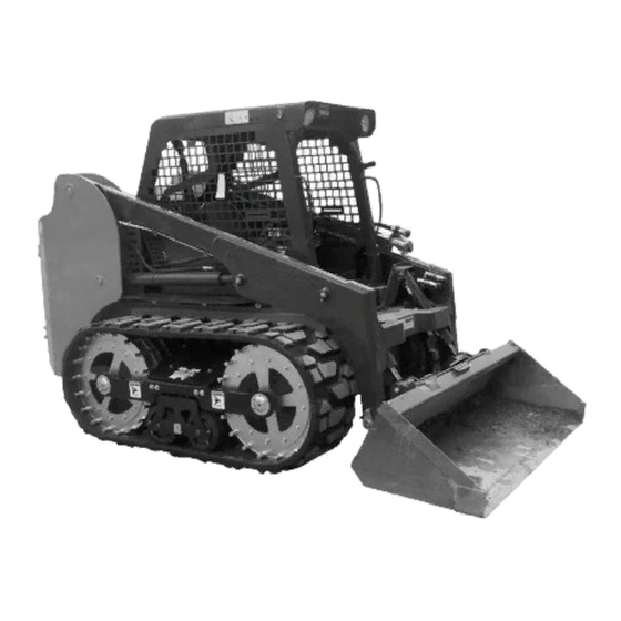
ORIGINAL RUBBER TRACKS ARE WARRANTED FOR A PERIOD OF 2 YEARS OR 1000 HOURS,
WHICHEVER OCCURS FIRST, STARTING FROM THE DELIVERY DATE TO THE FIRST USER.
TRACKS WILL BE PRO-RATED AFTER THE FIRST 300 HOURS OF OPERATION.
1. FAILURE TO PROVIDE HYUNDAI A COMPLETE COPY OF THE OWNERS WARRANTY
REGISTRATION AND DELIVERY FORM WITHIN 30 DAYS FROM THE DATE OF THE FIRST
DELIVERY.
2. FAILURE TO PERFORM PROPER MAINTENANCE, SERVICE, OR OPERATING PROCEDURES AS
RECOMMENDED IN THE OWNERS AND OPERATORS MANUAL.
3. REPAIR OR REPLACEMENT BY ANYONE OTHER THAN AN AUTHORIZED DEALER.
4. MISUSE, ABUSE, NEGLECT, OR IMPROPER ADJUSTMENT, ACCIDENT OR IMPROPER
APPLICATION.
5. ANY MODIFICATION OR REMOVAL OF PARTS, UNLESS AUTHORIZED BY HYUNDAI EQUIPMENT
2000 INC.
FOR INFORMATION ON LOADERS LIMITED WARRANTY PLEASE REFER TO WARRANTY STATEMENT
47384/1 (UNITED STATES, CANADA AND AUSTRALIA) OR STATEMENT 48053 (ALL OTHER COUNTRIES)
WHICH IS INCLUDED WITH YOUR DELIVERY PACKAGE.
N.B. Read and practice your Hyundai operating and servicing instructions. Failure to do this may void the warranty.
PERFORMANCE OR OTHER CONDITION.
FAILURE OF THE PRODUCT.
TRACK LOADER WARRANTY
THE FOLLOWING WILL VOID THE WARRANTY:
Advertisement
Table of Contents

Summary of Contents for Hyundai HSL1500T Wheel
- Page 1 FOR INFORMATION ON LOADERS LIMITED WARRANTY PLEASE REFER TO WARRANTY STATEMENT 47384/1 (UNITED STATES, CANADA AND AUSTRALIA) OR STATEMENT 48053 (ALL OTHER COUNTRIES) WHICH IS INCLUDED WITH YOUR DELIVERY PACKAGE. N.B. Read and practice your Hyundai operating and servicing instructions. Failure to do this may void the warranty.
- Page 2 Operating Procedures (Wheel Loader) Torque Specifications Operating Procedures (Track Loader) Decals Filling From A Pile Digging with a Bucket ATTACHMENTS AND BUCKETS Leveling and Backfilling Hyundai Approved Buckets And Auxiliary Hydraulics Attachments Lifting Towing 3.10 Securing and Transporting 3.11 Lowering Lift Arms 3.12...
- Page 3 FOREWORD This book has been written to give the Owner / Operator necessary operating, servicing and preventative maintenance instructions on the loader. Read this manual completely and know the loader before operating or servicing it. Do not do any service procedures that are not in the Operator’s manual. Only service personnel that have had training in the service of this loader can do these service procedures.
-
Page 4: Safety Precautions
1. SAFETY PRECAUTIONS The following precautions are suggested to help prevent accidents. A careful operator is the best operator. Most accidents can be avoided by observing certain precautions. Read and take the following precautions before operating this loader to help prevent accidents. Equipment should be operated only by those who are responsible and instructed to do so. -
Page 5: Emergency Exit
1. SAFETY PRECAUTIONS SAFETY DECAL EXPLANATIONS EMERGENCY EXIT 36841 Pull on the tag on the top of the rear window to remove the rubber cord. Push the rear window out of the rear of the cab and exit through the opening. WARNING: STAY CLEAR OF FRONT OF LOADER 41066... -
Page 6: Start Safely
1. SAFETY PRECAUTIONS CHECK THE CONDITION OF THE SAFETY AND WARNING LABELS 1. Keep the safety and warning labels clean and legible. 2. Wash the labels with soap and water. Dry with a soft cloth. 3. Replace all damaged and lost labels. If a part with a safety or warning label affixed to it needs replacing, ensure the new part also has the warning or safety label. -
Page 7: Park Safely
1. SAFETY PRECAUTIONS PARK SAFELY Select level ground whenever possible. If you must park on a slope or incline, position the machine at right angles to the slope. Lower the attachment to the ground, engage the parking brake and block the wheels (C359). For track loaders follow the same procedure except place your blocking immediately in front of or behind the... - Page 8 2. CONTROLS 2. CONTROLS 2. 1 Instrument Panel 2. 2 Control Lever Handles 2. 3 Seat and Seat Belt 2. 4 Seat Bar 2. 5 Parking Brake 2. 6 Throttle Control 2. 7 Lift Arm Supports 2. 8 Steering Controls 2.
-
Page 9: Instrument Panel
2. CONTROLS INSTRUMENT PANEL 9 10 11 12 13 14 15 16 17 18 20 21 22 23 Fig. 2.1A C3170 1. Fuel Gauge: The fuel gauge indicates the quantity of Brake Indicator Light: The brake light will fuel remaining in the fuel tank. illuminate when the parking brake is engaged. - Page 10 2. CONTROLS CONTROL LEVER HANDLES Fully retract lift arm support pins before IMPORTANT RH Control Handle LH Control Handle raising or lowering lift arms. Air Cleaner Indicator Light: This light will illuminate when there is an obstruction in the intake or when the air filter needs servicing.
-
Page 11: Seat And Seat Belt
2. CONTROLS SEAT AND SEAT BELT Fig. 2.3A1 C4436 The loader is equipped with a suspension seat. The seat can be adjusted forward or back (1) for operator comfort. (Fig. 2.3A1). The suspension seat can also be adjusted for an operators weight accordingly (2). This gives the loader operator the option of having more or less firmness to the seat while it is being used (Fig. -
Page 12: Rear Window
2. CONTROLS 2. 4 SEAT BAR For operator protection the loader is equipped with a seat bar. The loader must be started with the operator seated in the loader and the seat bar in the up position. To raise the seat Seat Bar Up bar, lift up on the bar (Fig. -
Page 13: Parking Brake
2. CONTROLS 2. 5 PARKING BRAKE The loader is equipped with park brakes, located inside the torque motors. The brakes are activated and de- activated by the seat bar, via charge pressure. When the seat bar is in the up position, the brake is activated (Fig. 2.5A). - Page 14 2. CONTROLS 2. 7 LIFT ARM SUPPORTS For your safety, the loader is equipped with lift arm supports to be used while performing regular service or maintenance work. The lift arm supports, when extended, prevent the lift arms from dropping if hydraulic pressure is relieved or the boom controls are accidentally cycled.
-
Page 15: Steering Controls
2. CONTROLS 2. 8 STEERING CONTROLS The two steering levers control speed, direction and turning of the loader. The R.H. lever controls the wheels on the R.H. side of the loader and the L.H. lever the L.H. wheels. Loader speed is controlled by the amount each lever is moved from centre or neutral position. - Page 16 2. CONTROLS ELECTRICAL SOLENOID AUXILIARY HYDRAULIC CONTROL AUXILIARY CONTROLS NEUTRAL Auxiliary Hydraulic (solenoid operated – standard). A switch located in the L.H. steering control lever (Fig. 2.9A) is used to engage the loader’s auxiliary hydraulic circuit to power attachments such as post hole augers, ROPS SIDE sweepers etc.
-
Page 17: Foot Controls
2. CONTROLS 2.10 FOOT CONTROLS Operation of the lift cylinders and bucket tilt cylinders are controlled by foot pedals (Fig. 2.10A) connected to a hydraulic control valve. The hydraulic control valve is a series type valve which allows simultaneous use of both the lift and bucket tilt circuits. - Page 18 2. CONTROLS 2.12 QUICK - TACH Push the locking lever (1) fully down (Fig. 2.12D) extending The quick - tach, which is standard equipment, allows the lock pins (Fig. 2.12E item 2) through the attachment and changing from one attachment to another quickly without securing the attachment.
-
Page 19: Electrical Panel
2. CONTROLS 2.13 ELECTRICAL PANEL FUSE PANEL (3) 4. Electric Fuel Solenoid Shutoff (15A) The loader is equipped with a 12 volt, negative ground electrical system. The fuse and relay panel are located in 5. Alternator (10A) the engine compartment on the engine cover. The panel 6. - Page 20 2. CONTROLS 2.14 TWO SPEED CONTROL (NOT CONTROL HANDLE AVAILABLE ON ALL MODELS) TWO SPEED A switch located on the LH steering control lever (Fig. HI / LOW 2.14A) is used to alternately activate the loader’s Two- Speed function. Pressing and releasing the switch will BUTTON activate the Hi-speed function.
- Page 22 3. OPERATION 3. OPERATION 3. 1 Starting Instructions 1. Pre-Starting Inspection 2. Starting Procedure 3. Shut-Off Procedure 3. 2 Operating Procedures 3. 3 Operating Track Loader 3. 4 Filling From a Pile 3. 5 Digging With a Bucket 3. 6 Leveling and Backfilling 3.
-
Page 23: Operation
3. OPERATION STARTING INSTRUCTIONS This engine is equipped 1. Pre-Starting Inspection with glow plugs. Do not IMPORTANT use ether or any high Before starting the loader complete the following energy fuels to assist inspection: starting. (1) Check the hydraulic oil level, engine oil level, engine coolant level and fuel supply. -
Page 24: Operating Procedures
3. OPERATION OPERATING PROCEDURES 1. When learning to use the loader operate at a slow rate. 2. Take advantage of the efficient operation of the loader. Keep the travel distance as short as possible. 3. Keep the work area as level as possible. 4. - Page 25 3. OPERATION 3. 3 OPERATING TRACK LOADER 4. Travel directly up or down a slope, not across the slope to prevent tracks from derailing. 5. Avoid operating the loader with one track on a slope and the other on flat ground or with the edge of the track turned up against a curb or mound (Fig.
- Page 26 3. OPERATION 3. 4 FILLING FROM A PILE Push down on the toe of the lift arm pedal and lower the lift arms completely down (Fig. 3.3A). Push the toe of the bucket pedal and place the cutting edge of the bucket on the ground. For hand control units, move the L.H.
- Page 27 3. OPERATION 3. 5 DIGGING WITH A BUCKET Push on the toe of the lift arm pedal and lower the lift arms completely down. Push on the toe of the bucket pedal and place the cutting edge of the bucket on the ground (Fig. 3.4D).
- Page 28 3. OPERATION 3. 6 LEVELING AND BACKFILLING Spread dirt on uneven ground by pushing on the heel of the lift arm pedal (Fig. 3.5G) to raise the lift arms and push on the toe of the bucket pedal to tilt the bucket down as you drive forward.
-
Page 29: Auxiliary Hydraulics
3. OPERATION 3. 7 AUXILIARY HYDRAULICS To operate an attachment such as a grapple fork the Left Hand Control Lever will be used. Push right of neutral on the Auxiliary Hydraulic Control Switch to open the grapple (See Fig. 3.6J). C3022 To close the grapple (Fig. - Page 30 3. OPERATION 3. 8 LIFTING Wheel Equiped Loaders The loader may be equipped with features to use in lifting (for example by crane onto a flatbed trailer or a flat car), for securing, and for extraction (from mud or snow). To facilitate this requires the optional lifting lugs.
- Page 31 3. OPERATION 3. 9 TOWING When winching or towing a stuck loader from the rear, always lower the lift arms until the attachment is resting on the ground and then follow the shut-off procedure (See Section 3.1-3). When winching or towing a stuck loader from the front, lower the attachment so that the front attachment points are accessible and have an assistant block the attachment, then follow the shut-off procedure (See...
- Page 32 3. OPERATION 3.10 SECURING AND TRANSPORTING There are three tie down points provided for securing the skid steer while transporting. One at the lower front and two at the rear (Fig. 3.9). Be sure the trailer and/or truck is of adequate size and capacity to safely transport your skid steer.
- Page 33 3. OPERATION 3.11 LOWERING LIFT ARMS (ENGINE OFF) In the event that you should have an electrical failure which renders your skid steer inoperable with the lift arms up, the following procedures would apply. To avoid personal injury: Do not leave lift arms up WARNING unless the lift arm supports are engaged.
- Page 34 3. OPERATION 3.12 ACCUMULATOR Accumulator The accumulator (Fig. 3.11A) stores system pressure until it is required to activate the electric auxiliary. The key must be placed in the “ON” position to operate the electric auxiliary (engine not running). The electric auxiliary and stored pressure in the accumulator can be used to release the hydraulic pressure in the auxiliary hydraulic system.
-
Page 35: Maintenance
4. MAINTENANCE 4. MAINTENANCE 4. 1 Preventative Maintenance Service Schedule 4. 8 Engine Maintenance Engine Specifications 4. 2 Service Access Oil Level Check Lift Arm Support Engine Oil and Filter Replacement Seat Removal V-Belt Tension Battery Access Adding Fuel Engine Compartment Fuel Filter Replacement Bleeding the Fuel System 4. -
Page 36: Service Required
4. MAINTENANCE 4.1 PREVENTIVE MAINTENANCE SERVICE SCHEDULE ITEM SERVICE REQUIRED Engine Oil Check level and add if necessary. Use 5W40 API Classification CF oil. Check level and add if necessary. Use 10W30 API Classification SJ (- Hydraulic Oil 20ºC to 35ºC) or 20W50 API Classification SJ (-10ºC to 45ºC) oil. Check level and add if necessary. - Page 37 • Tighten all connections before starting engine or pressurizing lines. If any fluid is injected into the skin, obtain medical attention immediately. To avoid personal injury service repairs must be WARNING performed by an authorized Hyundai dealer.
-
Page 38: Service Access
4. MAINTENANCE 4. 2 SERVICE ACCESS Lift Arm Support For safety while performing regular service or maintenance work, the loader is equipped with lift arm support pins. The lift arm support pins, when extended, prevent the lift arms from dropping if hydraulic pressure is relieved or the hydraulic controls are accidentally cycled. - Page 39 4. MAINTENANCE Engine Compartment Door Latch The engine compartment is completely enclosed for component protection and lockable to discourage vandalism. For servicing, the rear door swings open and the engine cover hinges up (Fig. 4.2F). To open, reach through the opening in the rear door (Fig. 4.2F), and pull outward releasing the door latch.
- Page 40 4. MAINTENANCE Tires and Wheel Nuts Torque Wheel Nuts 100 - 110 lbs. ft. (136 - 149 Nm) Inspect tires for wear or damage. Check and inflate tires to correct pressure: 12.00 x 16.5 ...40 - 45 PSI (276 - 310 kPa) Tires can be inflated to 50 PSI (345 kPa) when operating on hard, flat surfaces.
- Page 41 4. MAINTENANCE 7. Lubrication (Track Loader) There are twenty two (22) grease fittings located on the track loader that require lubrication every eight hours. Lubricate with a good quality multi-purpose lithium based grease. Grease all hinge pin fittings and pivot bearings until excess shows.
-
Page 42: Hour Service Check
1.7 Engine Speed: Check engine speed and if adjustment is necessary, Fig. 4.3G C3790 contact a Hyundai Equipment dealer. 1.8 Fan Drive: Inspect fan, bolts, v-belt and guard to ensure there is no buildup of dirt, trash, or wear. Use compressed air... - Page 43 Inspect pumps and motors for leaks. If the safety controls are malfunctioning or require 2.7 Oil Cooler: adjustment, consult your Hyundai Equipment Dealer Inspect the oil cooler for leaks, fin damage or clogged for service. Lubricate linkage with a silicone based with dirt.
- Page 44 4. MAINTENANCE 4.6 Quick-Tach, Operation & Linkage: General Ensure the quick-tach linkage operates smoothly without binding and engage completely. 7. 1 Tire Pressure: Check tire pressure and if necessary inflate to the 4.7 Seat Belt: following pressures: Check seat belt condition. If necessary replace. 12.00 x 16.5 .
-
Page 45: Final Drive Maintenance
4. MAINTENANCE 4. 6 FINAL DRIVE MAINTENANCE Oil Level Check Scrapers The loader has two independent final drive housings. Check the lubricating oil level with the loader on a level surface. Remove the check plug (Fig. 4.6A) located on the front of the loader to determine the oil level. - Page 46 4. MAINTENANCE 4. 7 HYDRAULIC/ HYDROSTATIC SYSTEM MAINTENANCE Oil Level Check Check the oil level of the hydraulic reservoir with the machine on a level surface with the lift arms down and the attachment grounded. Shut off the engine. Open the rear door and check the oil level sight gauge (Fig.
- Page 47 Remove any metal particles stuck to the magnet. Seal the plug with teflon tape when replacing. Fig. 4.7C C3785 Hyundai recommends that you abide by all IMPORTANT applicable environmental regulations when disposing of oil.
- Page 48 4. MAINTENANCE 5. Oil Cooler and Cooling Fan Oil returning from the control valve is circulated through the oil cooler before being sent to other parts of the hydraulic system. An engine cooling fan drives air through the oil cooler when the rear door is closed.
-
Page 49: Engine Maintenance
4. MAINTENANCE 4. 8 ENGINE MAINTENANCE To avoid personal injury: Engine Specifications Stop, Cool and Clean the engine of flammable Make ..............Kubota WARNING materials before Model ..............V3300T servicing. Never service No. of Cyls ..............4 or adjust machine with engine running. - Page 50 4. MAINTENANCE 4. V-Belt Tension Check the V-belt tension midway between the crankshaft Fan Pulley pulley and alternator pulley (Fig. 4.8C). Deflection should Alternator be between 1/4 to 3/8 in. (7-9 mm). Pulley 5. Adding Fuel Use No. 2 diesel fuel only. Total tank capacity 28.7 gal (109 L).
- Page 51 4. MAINTENANCE Bleeding the Fuel System Air must be removed from the fuel after replacement of the fuel filter element, or when the tank has been run out of fuel, before starting the engine. To remove air, ensure the fuel inlet shut - off located on the side of the fuel tank is open (Fig.
-
Page 52: Air Cleaner Maintenance
4. MAINTENANCE 4. 9 AIR CLEANER MAINTENANCE Daily Maintenance Inspect the air cleaner canister for holes, dents, missing or mis-aligned gaskets. Check all hose clamps for tightness and inspect the hose and Air Cleaner vacuator valve for damage (Fig. 4.9A). Hose Servicing Cleaner Element (Fig. -
Page 53: Engine Cooling System
4. MAINTENANCE 4. 10 ENGINE COOLING SYSTEM The engine cooling system fluid is a 50 / 50 mixture of Coolant Fill ethylene glycol and water. To maintain the fluid level, add coolant to the overflow Coolant Level reservoir (Fig. 4.10A). The overflow reservoir should be checked daily when the engine is cold. -
Page 54: Electrical System
4. MAINTENANCE 4. 11 ELECTRICAL SYSTEM To prevent personal injury Battery Maintenance and Boosting DO NOT charge a frozen battery because it can Inspect the batteries on a regular basis for damage such as explode and cause WARNING a cracked or broken case or cover which would allow personal injury. - Page 55 4. MAINTENANCE ELECTRICAL SCHEMATIC – ROPS YELLOW 18 DIRECTIONAL INDICATOR LH YELLOW 18 LOW CHARGE PRESSURE DIRECTIONAL INDICATOR RH BRAKE 400V GREEN 18 BATTERY HI-FLOW HYD PREHEAT AUX HYD AIR FILTER LIGHTS DIPPED LOW BEAM HYD OIL TEMP SEAT BELT COOLANT TEMP BEACON GREEN 18...
- Page 56 4. MAINTENANCE 3. ELECTRICAL SCHEMATIC – ENGINE YELLOW 18 GRAY WHT BLACK 18 WHITE 18 WHITE 18 BLACK 18 WHITE 18 BLACK 18 GRAY WHT GRN GRN GRN 18 C3886...
-
Page 57: Tire Maintenance
4. MAINTENANCE 4. 12 TIRE MAINTENANCE Use a clip-on tire chuck with a remote hose and gauge which allows the operator to stand clear of Tire Inflation and Service the tire while inflating it. Upon receiving your loader, check the air pressure 1.10 After seating the beads, adjust inflation pressure to in the tires as indicated in the tables. - Page 58 4. MAINTENANCE 4. 13 TRACK MAINTENANCE Damaged Area of Track 1. Track Inspection Inspect the tracks daily. Look for signs of excessive wearing, cut, and/or other damage. If damage is found determine the cause. (Fig. 4.13A) Fig 4.13A C4393 2. Roller Inspection Roller and Mount Inspect the rollers and roller mount for signs of damage and/or excessive wearing.
-
Page 59: Track Maintenance
4. MAINTENANCE 4. 13 TRACK MAINTENANCE Scrapers 5. Scraper Inspection Inspect scrappers for damage and wear and replace if needed. (Fig. 4.13D). C4414 To avoid personal injury Fig 4.13D do not operate the loader WARNING without the rear wear guard firmly in place. -
Page 60: Troubleshooting
4. MAINTENANCE 4. 14 TROUBLESHOOTING 1. Hydraulic System Problem Cause Remedy Loss of hydraulic power (no flow Reservoir low on fluid Replenish with 10W30 API SJ oil. from gear pump) Check for hose or fitting leaking. Coupling between engine and pump Inspect and replace damaged parts. - Page 61 4. MAINTENANCE 1. Hydraulic System (Continued) Problem Cause Remedy Foot pedal linkages out of Adjust foot pedal linkages. Foot pedals do not operate smoothly adjustment Foot pedal linkages need lubrication Lubricate with a silicone based lubricant. 2. Hydrostatic Drive Problem Cause Remedy No power on one side (both...
- Page 62 4. MAINTENANCE 3. Final Drive Transmission Problem Cause Remedy Final drive transmission noisy No lubricating oil Check and bring oil to the proper level. Use 10W30 API SJ engine oil. Axles have too much end play Preload axle bearings removing all end play.
- Page 63 4. MAINTENANCE 5. Electrical (Continued) Problem Cause Remedy Engine will not crank over Fuse burnt Check and replace. (continued) Defective relay Check relay continuity. If defective, replace. Ignition switch failure Check continuity, repair or replace. Engine cranks over, but will not start Auxiliary hydraulics engaged Engine will smoke, but not run unassisted by starter.
- Page 64 4. MAINTENANCE 6. Engine (Continued) Problem Cause Remedy Starter does not run Battery discharged Charge. Starter malfunctioning Repair or replace. Key switch malfunctioning Repair or replace. Wiring disconnected Connect. Engine revolution is not smooth Fuel filter clogged or dirty Clean or change. Air cleaner clogged Clean or change.
- Page 65 4. MAINTENANCE 6. Engine (Continued) Problem Cause Remedy Engine oil insufficient Replenish. Engine overheated Fan belt broken or elongated Change or adjust. Cooling water insufficient Replenish. Radiator net and radiator fin clogged Clean. with dust Inside of radiator corroded Clean or replace. Cooling water flow route corroded Clean or replace.
- Page 66 4. MAINTENANCE 4.15 HYDRAULIC / HYDROSTATIC CIRCUIT C3962 Fig. 4.14...
-
Page 67: Special Tools
4. MAINTENANCE 4.16 SPECIAL TOOLS Part # DESCRIPTION MODEL ILLUSTRATION SEAL INSTALLATION TOOL: HSL500T 962201 To install axle seal in final drive housing. Qty. 3 required HSL680T 955281 C3651 AXLE EXTRACTOR TOOL: To remove axle from final drive housing. 955283 HSL500T, HSL680T (6 Bolt) Qty. - Page 68 4. MAINTENANCE 4.16 SPECIAL TOOLS (Cont’d) Part # ILLUSTRATION DESCRIPTION MODEL UNIVERSAL TOOL KIT: 1 each. Combination wrench 7/16”, 1/2”, Universal U-1288 9/16”, 11/16”, 3/4”, 1 1/16”, 1 1/4”. Sockets, Tool Kit MODELS 1”, 1/2” drive, 7/8”, 1/2” drive, tool pouch, allen wrench 5/32”...
- Page 69 4. MAINTENANCE 4.15 SPECIAL TOOLS (Cont’d) Part # ILLUSTRATION DESCRIPTION MODEL 43979 CHAIN PULLER MODELS C1840 SPANNER WRENCH 2’’ - 4 3/4’’: 43980 To Repair Hydraulic Cylinders MODELS C1841 PHOTO SENSOR / WHEEL SPEED 43981 TACHOMETER (Dual Function) MODELS C1837 FORCE GAUGE, PUSH PULL: HSL1200T, For Measuring Restraint Bar Brake...
-
Page 70: Specifications
5. SPECIFICATIONS 5. SPECIFICATIONS 5. 1 Loader Specifications 5. 2 Torque Specifications 5. 3 Decals... -
Page 71: Loader Specifications
5. SPECIFICATIONS LOADER SPECIFICATIONS C4343 Dimensions: (With Std. Tires & Dirt Bucket) HSL1500T Wheel HSL1500T Track A. Overall operating height............157” (3988 mm).......156.25” (3969mm) B. Height to hinge pin..............123.8” (3143 mm)......123.12” (3127mm) C. Overall vehicle height ..............84” (2134 mm) ........84” (2134mm) D. - Page 72 5. SPECIFICATIONS Controls VEHICLE: Steering direction and speed controlled by two hand operated control levers. HYDRAULICS: Lift and bucket tilt are controlled by separate foot pedals or hand controls. Auxiliary hydraulics controlled by electric solenoid. ENGINE: Hand throttle, key type ignition switch and shutoff. Engine Make and model ............................Kubota V3300-T Cylinders ....................................4...
-
Page 73: Torque Specifications
5. SPECIFICATIONS Electrical Alternator ..................................60 A Battery ..................................2 x 12V Type (BCI GROUP)................................34/78 Cranking Amps ..............................730 each (1460) Starter................................12 V (2.5 kW) Circuit breaker setting ..............................40 A Tires Standard ....................12.00 x 16.5, 6 ply rating, 40-45 PSI (276-310 kPa) Fluid Capacities Fuel tank ....................28.7 gal. - Page 74 5. SPECIFICATIONS 5.3 DECALS (320)
- Page 75 5. SPECIFICATIONS 5.3 DECALS (HSL1500T)
- Page 76 5. SPECIFICATIONS 5.3 DECALS (320)
-
Page 77: Attachments And Buckets
6. ATTACHMENTS AND BUCKETS 6. ATTACHMENTS AND BUCKETS 6. 1 Hyundai Approved Buckets and Attachments... - Page 78 6. ATTACHMENTS AND BUCKETS 6. 1 HYUNDAI APPROVED BUCKETS AND ATTACHMENTS BUCKETS Cat. # Description SAE Heaped Capacity (ft³) Approx. Weight 1956 78” Snow and Light Material Bucket 28.3 518 lb 2009 78” Produce Bucket 34.3 604 lb 3184 80” Dirt Bucket 16.2...
- Page 79 HYUNDAI APPROVED BUCKETS AND ATTACHMENTS (Continued) ANGLE BROOM Cat. # Description Approx. Weight 3188 84” Angle Broom With Manual Angle (shipped from Hyundai) 915 lb 3189 84” Angel Broom With Manual Angle (direct shipped from manufacturer) 915lb 3192 84” Angle Broom With Hydraulic Angle (shipped from Hyundai)
- Page 80 3247 90” Power Rake w/Manual Angle (direct shipped from manufacturer) 1075 lb 3248 90” Power Rake w/Manual Angle and Float Linkage (shipped from Hyundai) 1075 lb 3249 90” Power Rake w/Manual Angle and Float Linkage (direct shipped from manufacturer) 1075 lb 3250 90”...