Advertisement
Quick Links
Surface Mounted Temperature Control
Application
This control incorporates a single-
pole, double-throw contact
mechanism and is designed
especially for mounting on hot
water pipes.
As a high temperature cutout
control, the contacts which open on
a rise in temperature are used. As
a low temperature cutout control for
use on unit heaters, the contacts
which open on a falling temperature
are used.
Do not install where the case
temperature exceeds 140°F (60°C)
or the sensing element temperature
exceeds 290°F (143°C).
All Series A19 temperature controls
are designed for use only as
operating controls. Where an
operating control failure would
result in personal injury and/or loss
of property, it is the responsibility of
the installer to add devices (safety,
limit controls) or systems (alarm,
supervisory) that protect against, or
warn of, control failure.
Adjustment and Operation
Adjusting screw "B," Fig. 3, permits
screwdriver adjustment of control
point between 100°F (38°C) and
240°F (116°C). The temperature
differential is factory set,
nonadjustable, and is
approximately 10F° (5.5C°)
depending on rate of temperature
change.
Convertible adjustment models can
be field converted from concealed
screwdriver slot adjustment to knob
adjustment or external screwdriver
slot adjustment. They are supplied
with a snap-in plug in the cover to
provide concealed screwdriver slot
adjustment. For knob adjustment
remove the snap-in plug and
assemble the knob to the slotted
shaft. For external screwdriver slot
adjustment remove the snap-in plug.
On boiler applications where the A19
© 1988 Johnson Controls, Inc.
Code No. LIT-121050
Form 997-360-5
A19D Series
is used as a high temperature cutout
control, follow the boiler
manufacturer's recommendations for
temperature setting. The heating
plant should be operated until the
maximum temperature setting
recommended by the boiler
manufacturer is reached. If the
control has not operated by this
time, turn the adjusting screw back
just to the point where the system
shuts down.
When used as a low temperature
cutout control on a unit heater the
control should be set high enough to
prevent the discharge of cold air.
Unless otherwise specified, a setting
of 120°F (49°C) should be used as a
starting point. If fan fails to start with
steam or hot water supply on, the
setting is too high. The setting is too
low if the fan delivers cool air after
the steam or hot water has shut off.
Installation
Mounting
Boiler Application
!
CAUTION: Do not install this
control on riser pipe
containing a flow control
device. The flow control
device will prevent
circulation of hot water
unless circulator is
operating.
Install the control on the vertical
riser pipe from the boiler
approximately 2 feet (.6 m) above
the boiler opening.
Immersion type controls are
normally used for cutout control
application on forced hot water
heating systems.
Unit Heater Control
Mount the control on the
horizontal return line adjacent to
the unit heater. In this position
Installation Sheets Manual 121
Temperature Controls Section A
Technical Bulletin A19D
Issue Date 0988
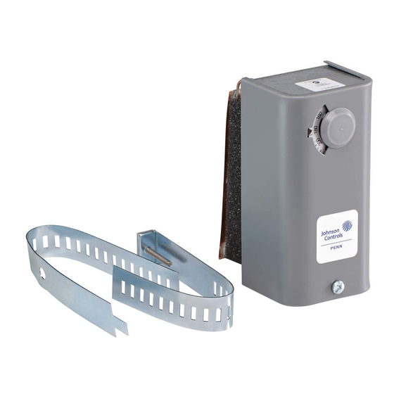
Fig. 1 -- Surface Mounted
Temperature Control less
mounting strap.
it will close the contacts when
hot condensate or hot water is
leaving the unit heater.
Other Applications
Control can be mounted in any
position on the pipe to sense
pipe temperature. The control is
not position sensitive.
1.
If a pipe is insulated, remove
a 5 in. (127 mm) section of
insulation. Scrape pipe
surface clean, removing
insulating material, scale
and rust.
2.
Remove the cover from the
control and fasten threaded
flange of the strap to the
control case using only 3 or 4
threads of mounting screw.
(See Fig. 7.) Place the control
Fig. 2 -- Controls with
convertible adjustment have
a snap-in plug in the cover
and a knob for field
installation.
1
Advertisement

Related Manuals for Johnson Controls A19D Series


Summary of Contents for Johnson Controls A19D Series
- Page 1 In this position a snap-in plug in the cover shaft. For external screwdriver slot adjustment remove the snap-in plug. and a knob for field On boiler applications where the A19 installation. © 1988 Johnson Controls, Inc. Code No. LIT-121050 Form 997-360-5...
- Page 2 For replacement control, contact control. If practical, replace a application. the nearest Johnson Controls portion of removed pipe wholesaler. insulation for appearance. CAUTION: Use terminal screws furnished (8-32 x Wiring 1/4 in.