Advertisement
Available languages
Available languages
Quick Links
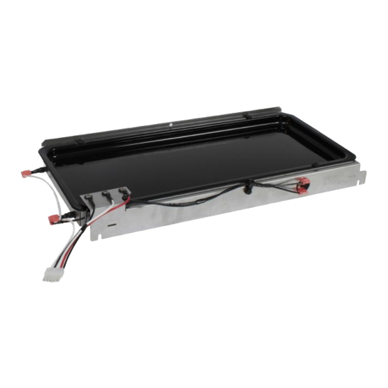
PVSHT2-1 HEATED HUMIDIFICATION TRAY. FOR USE ON: PVS(18,35)(N,P)-2
INSTRUCTIONS MUST BE LEFT WITH THE OWNER FOR FUTURE REFERENCE AFTER INSTALLATION.
TOOLS NEEDED:
•
1/4" Nut Driver
•
or Socket
•
Pliers
•
Side Cutter
•
ELECTRICAL SHOCK HAZARD! Disconnect all electrical
power to the wall furnace prior to servicing.
INSTALLATION
1.
Carefully remove the front cover of the wall furnace by lifting
up and pulling out.
2.
Turn off the main power switch. Or unplug the wall furnace
power cord from the wall outlet. See Figure 1.
35467-3-0320
OWNER'S MANUAL
AND INSTALLATION
INSTRUCTIONS
5/16" Nut Driver
10"+ Long or Socket
With Extension
Small level
WARNING
Figure 1
Empire Comfort Systems Inc. • Belleville, IL
3.
Remove the lower louver assembly by removing the four (two
each side) hex head screws fastening the louvers to the outer
cabinet with the 5/16 nut driver.
4.
If wall furnace has been installed and operated, the condensate
trap must be drained. Disconnect the clear hose from the front
inducer tap and use to drain the condensate from the tap into
a cup. Replace the line when done. See Figure 2.
Figure 2
Page 1
Advertisement

Summary of Contents for Empire Heating Systems PVSHT2-1
- Page 1 OWNER’S MANUAL AND INSTALLATION INSTRUCTIONS PVSHT2-1 HEATED HUMIDIFICATION TRAY. FOR USE ON: PVS(18,35)(N,P)-2 INSTRUCTIONS MUST BE LEFT WITH THE OWNER FOR FUTURE REFERENCE AFTER INSTALLATION. Remove the lower louver assembly by removing the four (two TOOLS NEEDED: each side) hex head screws fastening the louvers to the outer •...
- Page 2 Remove and discard the hose clamp and barb from the black 8. Insert a flat screwdriver into the slots on the condensate tray condensate drain line from the bottom left of the condensate bracket to level the tray from front to back and side to side. trap. Rotate the hose toward the front of the furnace. See Verify with a small level.
- Page 3 11. Slide the new hose clamp over the “L” shaped end of the 14. Plug the connector from the heated tray’s wire harness into the connector on the relay’s wire harness. See Figure 11. metal condensate tube connected to the relay wire harness. 12.
-
Page 4: Wiring Diagram
INDEX PART DESCRIPTION QUANTITY HEATED TRAY ASSEMBLY 35468 Condensate Tray Box 32181 Condensate Tray Bracket 32330BL Porcelain Condensate Tray 32342 Insulation Pad R11700 Heating Element R11707 Sensing Screw, 8-32 x 5/8 R11708 Sensing Screw, 8-32 x 1 R11709 Limit Switch R12040 Condensate Tray Harness RELAY ASSEMBLY... - Page 5 LE MANUEL DU PROPRIÉTAIRE ET INSTALLATION INSTRUCTIONS PLATEAU D'HUMIDIFICATION CHAUFFÉ PVSHT2-1. POUR UTILISATION SUR: PVS (18,35) (N, P)-2 LES INSTRUCTIONS DOIVENT ÊTRE LAISSÉES AU PROPRIÉTAIRE POUR RÉFÉRENCE FUTURE APRÈS L'INSTALLATION. Retirez le volet inférieur en retirant les quatre vis à tête OUTILS NÉCESSAIRES:...
- Page 6 Retirez et jetez le collier de serrage et le raccord cannelé Insérez un tournevis plat dans les fentes du support du bac de la conduite noire d'évacuation des condensats en bas à à condensats pour niveler le bac d'avant en arrière et d'un gauche du purgeur de condensats.
- Page 7 11. Faites glisser le nouveau collier de serrage sur l'extrémité en 14. Branchez le connecteur du faisceau de câbles du plateau forme de «L» du tube de condensat métallique connecté au chauffant dans le connecteur du faisceau de câbles du faisceau de câbles du relais.
-
Page 8: Schéma De Câblage
N ° N ° DE LA DESCRIPTION QUANTITÉ D'INDEX PIÈCE ASSEMBLAGE DU PLATEAU CHAUFFANT 35468 Bac à condensats 32181 Support de bac à condensats 32330BL Bac à condensats en porcelaine 32342 Coussin isolant R11700 Élément chauffant R11707 Vis de détection, 8-32 x 5/8 R11708 Vis de détection, 8-32 x 1 R11709...