Advertisement
Available languages
Available languages
Quick Links
WHITE-RODGERS
Operator: Save these instructions for future use!
FAILURE TO READ AND FOLLOW ALL INSTRUCTIONS CAREFULLY BEFORE
INSTALLING OR OPERATING THIS CONTROL COULD CAUSE PERSONAL
INJURY AND/OR PROPERTY DAMAGE.
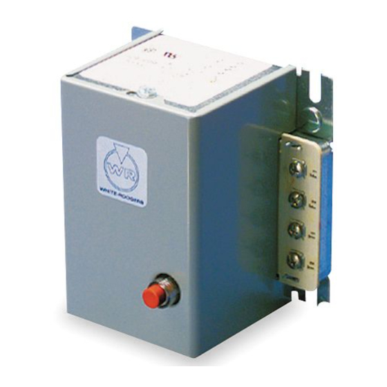
The type 668 Oil Burner Control provides safe operation
of oil burners on heating plants where ignition during the
entire burner cycle is desired.
The 668 is used with the 956 Flame Detector
If in doubt about whether your wiring is millivolt, line, or
low voltage, have it inspected by a qualified heating and
air conditioning contractor, electrician, or someone famil-
iar with basic electricity and wiring.
Do not exceed the specification ratings.
All wiring must conform to local and national electrical
codes and ordinances.
This control is a precision instrument, and should be
handled carefully. Rough handling or distorting compo-
nents could cause the control to malfunction.
Electrical Data
Input voltage: 668
668H
Maximum Load Current:
Oil Burner Motor (Orange Wire):
10 Amps F.L. 60 Amps L.R.
Ignition Transformer:
360VA (3.0 Amps)
Relay Voltage: 668
668H
The proper Location and Mounting of the primary oil
burner control panel on the burner and the flame detector
with respect to the oil flame shall be determined by the
furnace, boiler, or burner manufacturer.
If this control, supplied as part of a furnace, boiler or
burner, is wired to the equipment or if the manufacturer
of such equipment provides instructions for wiring this
WHITE-RODGERS DIVISION
EMERSON ELECTRIC CO.
9797 REAVIS RD., ST. LOUIS, MO. 63123
(314) 577-1300, Fax (314) 577-1517
9999 HWY. 48, MARKHAM, ONT. L3P 3J3
(905) 475-4653, FAX (905) 475-4625
* Formerly called constant ignition.
120V. AC, 60Hz.
220V. AC, 50/60Hz.
24 Volts AC, 60Hz.
24 Volts AC, 50/60Hz
Intermittent Ignition* – Non Recycling
OIL BURNER CONTROL
With Series 956 Flame Detector
INSTALLATION INSTRUCTIONS
To prevent electrical shock and/or equipment
damage, disconnect electric power to system, at
main fuse or circuit breaker box, until installation
is complete.
!
Do not use on circuits exceeding specified volt-
ages. Higher voltages will damage control and
could cause shock or fire hazard.
Room Thermostat:
Set adjustable heat anticipator at 0.4 Amps. For fixed
anticipation thermostats, use 0.35 to 0.45 Amp.
heater.
Safety Timing:
668, 668H-401 to 499: 45 seconds
668, 668H-501 to 599: 30 seconds
668, 668H-601 to 699: 15 seconds
INSTALLATION AND WIRING
control, then follow his recommendations. If no special
wiring instructions are given, then follow the electrical
connections shown on this diagram for a simple system.
For more complicated systems, especially for hot water
heating, consult the manufacturer of the heating plant for
full details of the desired sequence of control operation.
Printed in U.S.A.
TYPE 668
DESCRIPTION
PRECAUTIONS
CAUTION
!
WARNING
SPECIFICATIONS
PART NO. 37-5456A
Replaces 37-1794 &
37-9517
9510
Advertisement

Related Manuals for White Rodgers 668


Summary of Contents for White Rodgers 668
-
Page 1: Specifications
FAILURE TO READ AND FOLLOW ALL INSTRUCTIONS CAREFULLY BEFORE INSTALLING OR OPERATING THIS CONTROL COULD CAUSE PERSONAL INJURY AND/OR PROPERTY DAMAGE. The type 668 Oil Burner Control provides safe operation of oil burners on heating plants where ignition during the entire burner cycle is desired. - Page 2 INSTALLATION AND WIRING CONT. All wiring should be done in accordance with local and national electrical codes and ordinances. LOW VOLTAGE PRIMARY CONTROL PRIMARY CONTROL THERMOSTAT ORANGE WIRE BLACK WHITE NUTS IGN. TRANS. LIMIT LINE BURNER MOTOR External Line Voltage Wiring TESTING The following control checks should be made after each installation to insure that the controls are correctly wired...
- Page 3 TESTING CONT. PART No. OF REPLACEMENT PART F142-0006 Cell only (Old Style) 4. If safety lockout problem is of an occasional nature the following additional check may be made to insure that flame detector location is not a marginal one: a.
-
Page 4: Spécifications
Le modèle 668 est employé avec le détecteur de flamme 956. Si vous n’êtes pas certain de la tension du câblage de votre système (soit en millivolts, à basse tension ou à la tension du secteur), faites inspecter celui-ci par un électricien, un entre-... - Page 5 INSTALLATION ET CÂBLAGE (SUITE) Tout le câblage doit être conforme aux codes et règlements locaux et nationaux qui régissent les installations électriques. COMMANDE PRINCIPALE À LA TENSION DU RÉSEAU COMMANDE PRINCIPALE THERMOSTAT ORANGE NOIR MARRETTES BLANC TRANSFO D’ALLUMAGE LIMITEUR RÉSEAU SOUS MOTEUR DE BRÛLEUR...
- Page 6 ESSAIS (SUITE) NOS DES PIÈCES DE RECHANGE F142-0006 Détecteur deul (ancien modèle) Si le problème lié au blocage de sécurité n’est qu’occasionnel, procédez à l’essai suivant pour vous assurer que l’emplacement du détecteur est convenable. Débranchez des bornes F les fils du détecteur. Branchez un cavalier sur une des bornes F.