Advertisement
WHITE-RODGERS
Operator: Save these instructions for future use!
FAILURE TO READ AND FOLLOW ALL INSTRUCTIONS CAREFULLY
BEFORE INSTALLING OR OPERATING THIS CONTROL COULD CAUSE
PERSONAL INJURY AND/OR PROPERTY DAMAGE.
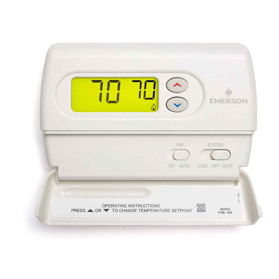
Your new White-Rodgers Digital Thermostat uses the technol-
ogy of a solid-state microcomputer to provide precise tempera-
ture control.
Features:
• Simultaneous heat and cool set point storage
• Pre-set temperature control
• Backlit display
• Battery powered (2 "AA" Energizer
This thermostat is intended for use with a low voltage system; do
not use this thermostat with a line voltage system. If in doubt
about whether your wiring is millivolt, line, or low voltage, have
it inspected by a qualified heating and air conditioning contractor
or electrician.
Do not exceed the specification ratings.
All wiring must conform to local and national electrical codes and
ordinances.
This control is a precision instrument, and should be handled
carefully. Rough handling or distorting components could cause
the control to malfunction.
CAUTION
!
To prevent electrical shock and/or equipment dam-
age, disconnect electric power to system at main fuse
or circuit breaker box until installation is complete.
ELECTRICAL DATA
Electrical Rating:
8 to 30 VAC 50/60 Hz. or D.C.
0.05 to 1.0 Amps (Load per terminal)
1.5 Amps Maximum Total Load (All terminals combined)
THERMAL DATA
Setpoint Temperature Range:
45 F to 90 F (7 C to 32 C)
Operating Ambient Temperature Range:
32 F to 105 F
Operating Humidity Range:
0 to 90% RH (non-condensing)
Shipping Temperature Range:
-4 F to 150 F
WHITE-RODGERS DIVISION
EMERSON ELECTRIC CO.
9797 REAVIS ROAD
ST. LOUIS, MISSOURI 63123-5398
®
alkaline batteries included)
Printed in U.S.A.
1F86-244
Non-Programmable Electronic Digital Thermostat
INSTALLATION AND
OPERATION INSTRUCTIONS
• LCD continuously displays set point and room temperature
•
F/ C convertibility
• Temperature range 45 to 90 F
• RC, RH, W, Y, G , O and B terminals
• B and O terminals for single stage heat pumps (no auxiliary
heat) or damper operation
• Set point storage in case of power loss
WARNING
!
Do not use on circuits exceeding specified voltage.
Higher voltage will damage control and could cause
shock or fire hazard.
Do not short out terminals on gas valve or primary
control to test. Short or incorrect wiring will damage
thermostat and could cause personal injury and/or
property damage.
Thermostat installation and all components of the
system shall conform to Class II circuits per the NEC
code.
APPLICATIONS
For use with:
•
Standard heat/cool or heat only systems
•
Electric heat systems
•
Gas or oil fired systems
•
Gas systems with intermittent ignition devices (I.I.D.)
and/or vent dampers
•
Hydronic (hot water or steam) systems
•
Single-stage heat pump systems (no auxiliary heat)
•
Millivolt systems
DO NOT USE WITH:
•
Multi-stage systems
•
Systems exceeding 30 VAC and 1.5 amps
•
3-wire zoned hydronic heating systems
DESCRIPTION
PRECAUTIONS
SPECIFICATIONS
PART NO. 37-6174A
0046
Advertisement

Related Manuals for White Rodgers 1f86-244


Summary of Contents for White Rodgers 1f86-244
-
Page 1: Specifications
Shipping Temperature Range: -4 F to 150 F WHITE-RODGERS DIVISION EMERSON ELECTRIC CO. 9797 REAVIS ROAD ST. LOUIS, MISSOURI 63123-5398 1F86-244 Non-Programmable Electronic Digital Thermostat INSTALLATION AND OPERATION INSTRUCTIONS • LCD continuously displays set point and room temperature • F/ C convertibility •... -
Page 2: Installation
INSTALLATION REMOVE OLD THERMOSTAT 1. Shut off electricity at the main fuse box until installation is complete. Ensure that electrical power is disconnected. 2. Remove the front cover of the old thermostat. With wires still attached, remove wall plate from the wall. If the old thermostat has a wall mounting plate, remove the thermostat and the wall mounting plate as an assembly. -
Page 3: Wiring Diagrams
JUMPER WIRE Heating NOTE Relay System For 2-wire Heat only attach to RH and W Figure 2. Typical wiring diagram for heat only, 3-wire, single transformer systems JUMPER WIRE Cooling System Relay 24 VAC Figure 3. Typical wiring diagram for cool only, 3-wire, single transformer systems NOTE RED jumper wire (provided with thermostat) must be... -
Page 4: Configuration Menu
OPERATION Before you begin using your thermostat, you should be familiar with its features and with the display and the location and operation of the thermostat buttons. Your thermostat consists of two parts: the thermostat cover and the base. To remove the cover, pull it straight out from the base. -
Page 5: Setting The Thermostat
2) Select FA or SL (Fast or Slow) Heating Cycle Rate - The FA setting is frequently used for gas, oil or electric heat. The SL setting produces a longer heating cycle which is nor- mally for hot water or steam (hydronic) systems. Both settings produce very accurate temperature control and can be set to your personal preference.