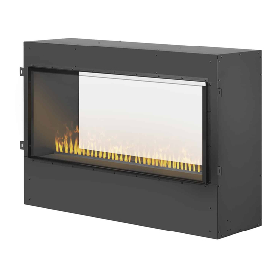
Dimplex CDFI-BX1000 Service Manual
Hide thumbs
Also See for CDFI-BX1000:
- Owner's manual (46 pages) ,
- Assembly instructions (3 pages) ,
- Assembly instructions (3 pages)
Advertisement
Quick Links
IMPORTANT SAFETY INFORMATION: Always read this manual first before attempting to service this
fireplace. For your safety, always comply with all warnings and safety instructions contained in this
manual to prevent personal injury or property damage.
Service Manual
Model
CDFI-BX1000 6909910100
CDFI-BX1500 6910370100
UL Part Number
7401070000R00
Advertisement

Summary of Contents for Dimplex CDFI-BX1000
- Page 1 Service Manual Model UL Part Number CDFI-BX1000 6909910100 CDFI-BX1500 6910370100 IMPORTANT SAFETY INFORMATION: Always read this manual first before attempting to service this fireplace. For your safety, always comply with all warnings and safety instructions contained in this manual to prevent personal injury or property damage.
-
Page 2: Table Of Contents
NOTE: Procedures and techniques that are considered important enough to emphasize. CAUTION: Procedures and techniques which, if not carefully followed, will result in damage to the equipment. WARNING: Procedures and techniques which, if not carefully followed, will expose the user to the risk of fire, serious injury, or death. www.dimplex.com... -
Page 3: Operation
CAUTION: If you need to continuously reset the heater, conditions and at least at yearly intervals. disconnect power to the unit and call Glen Dimplex Americas at 1-888-346-7539 for technical support. Please have your model and serial number ready when calling. -
Page 4: Wiring Diagram
Wiring Diagram Live Neutral Live +24V Heat BOX Neutral Block Diagram for CDFI-BX1500 WHITE-N WHITE-N PRO BOX BLACK-L BLACK-L CDFI500-PRO RELAY BOARD GREEN-G GREEN-G CDFI-BX1500 JUNCTION BOX WHITE-N WHITE-N 120V BLACK-L BLACK-L CDFI1000-PRO POWER SUPPLY GREEN-G GREEN-G www.dimplex.com... -
Page 5: Exploded Parts Diagram
CDFI-BX1000 ....2203610300RP CDFI-BX1000 ......FG1000 CDFI-BX1500 . -
Page 6: Relay Board Replacement
6. Unscrew the four screws that secure the board to the standoffs. (Figure 2) NOTE: On the CDFI-BX1000 with no MOD des- ignation, these will instead be snap-in standoffs. The snap-in standoffs will need to be cut, and the new board will need to be installed using self- adhesive standoffs. -
Page 7: Heater Assembly Replacement
12. Reassemble the unit in the reverse order as above. as the screws in the back (CDFI-BX1000 has 8 screws in total, and the CDFI-BX1500 has 12 screws in total). (Figure 3) -
Page 8: Troubleshooting Guide
For troubleshooting related to the remote, flame, sound, or plumbing, refer to the CDFI Cassette Service Manual. 1-888-346-7539 | www.dimplex.com In keeping with our policy of continuous product improvement, we reserve the right to make changes without notice. © 2019 Glen Dimplex Americas www.dimplex.com...


