Table of Contents
Advertisement
Quick Links
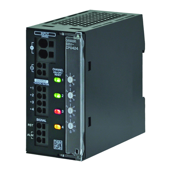
DC Electronic Circuit Protector
S8V-CP
Simplified safety design of DC circuits
Reliable DC circuit protection in the
event of short circuits or overcurrent
Saves space even with multi-channels
Sequential start-up of outputs
to avoid start-up trouble
• Push-in plus terminal block adopted
• Push button with indicator to help you understand
each output status at a glance
• Switch lets you set the rated output current appropriately
for each output depending on load
• Lineup of a UL Class 2 output-compatible model
Refer to Safety Precautions on page 10.
Model Number Structure
Model Number Legend
S8V-CP @@ 24 @
Series name
(1)
(2) (3)
(1) Number of Outputs
Code
04
08
(2) Rated input voltage
Code
24
List of Models
Unit
Number of Outputs
4 outputs
8 outputs
Not all combinations are possible. Refer to List of Models in Ordering Information, below.
Number of Outputs
4 outputs
8 outputs
Rated input voltage
24 VDC
UL Class 2 output
No
Yes
No
(24 VDC 4 Outputs/8 Outputs Type)
For the most recent information on models that have been
certified for safety standards, refer to your OMRON website.
(3) UL Class 2 output
Code
S
No
Model
S8V-CP0424
S8V-CP0424S
S8V-CP0824
UL Class 2 output certified
Yes
No
1
Advertisement
Table of Contents

Related Manuals for Omron S8V-CP Series


Summary of Contents for Omron S8V-CP Series
- Page 1 • Lineup of a UL Class 2 output-compatible model For the most recent information on models that have been certified for safety standards, refer to your OMRON website. Refer to Safety Precautions on page 10. Model Number Structure Model Number Legend Not all combinations are possible.
- Page 2 S8V-CP Ratings, Characteristics, and Functions Model S8V-CP0424 S8V-CP0424S S8V-CP0824 Number of Outputs Item UL Class 2 output Rated input voltage 24 VDC 24 VDC 24 VDC (Input voltage allowable range) (20 to 30 VDC) (20 to 28.8 VDC) (20 to 30 VDC) Allowable input current *1 40 A 15.2 A...
-
Page 3: Output Status
S8V-CP Tripping Functions Current tripping If the output current of each output exceeds the current tripping, the output is tripped by a semiconductor switch (MOS FET) in accordance with the current tripping characteristic. Over voltage tripping With the S8V-CP0424S, if the input voltage exceeds 28.8 V, all outputs are tripped by a semiconductor switch (MOS FET). If the input voltage becomes 28.8 V or less, all outputs automatically return to the previous state. -
Page 4: Block Diagrams
S8V-CP Connections Block Diagrams S8V-CP0424 MOS FET FUSE 15A +VI1 +VO1 INPUT +VI2 +VO2 OUTPUT +VO3 +VO4 MOS FET RELAY ALM1 SIGNAL CONTROL CIRCUIT OUTPUT SIGNAL ALM2 -VI1 INPUT -VI2 S8V-CP0424S MOS FET +VI1 +VO1 INPUT +VI2 +VO2 OUTPUT +VO3 +VO4 MOS FET RELAY ALM1... -
Page 5: Connection Example
S8V-CP Connection Example POWER SUPPLY S8V-CP +VDC +VI1 +VO1 +VI2 +VO2 -VDC +VO3 -VI1 -VI2 +VO4 RESETSIGNAL ALM1 LOAD POWER LINE/LOAD LINE ALM2 INDICATOR SIGNAL LINE COMMON TERMINALBLOCK Note: 1. Wire so that the load current does not flow into -VI1 or -VI2. 2. - Page 6 S8V-CP Construction and Nomenclature Nomenclature 4 outputs type 8 outputs type S8V-CP0424 S8V-CP0424S S8V-CP0824 (10) (11) (12) (10) (10) (13) (11) (11) (14) (12) (12) (15) (13) (13) (16) (17) Terminal name Name Function The indicator shows the connected/tripped status of each output. Push button (ON/OFF/RESET) The push button switch is used to switch between the connected/tripped status with indicator...
-
Page 7: Engineering Data
S8V-CP Engineering Data Derating Curves S8V-CP0424 S8V-CP0424S S8V-CP0824 10 20 30 40 50 60 70 80 10 20 30 40 50 60 70 80 10 20 30 40 50 60 70 80 Ambient operating temperature (°C) Ambient operating temperature (°C) Ambient operating temperature (°C) Current Tripping Characteristics S8V-CP0424, S8V-CP0824... - Page 8 S8V-CP Dimensions (Unit: mm) Unit S8V-CP0424 44.8 ±1 (1.1) 94.8 ±1 11.9 90.8 34.3 18.7 ±1 (3.5) Rail stopper (10.4 max. when sliding) S8V-CP0424S 44.8 ±1 (1.1) 94.8 11.9 ±1 90.8 34.3 18.7 ±1 (3.5) Rail stopper (10.4 max. when sliding) S8V-CP0824 (1.6) 122.5...
- Page 9 S8V-CP DIN Rail Mounting (Order Separately) Mounting Rail (Material: Aluminum) PFP-100N ±0.15 PFP-50N ±0.3 ±0.15 15 (5) * 1,000 (500) * * ( ) indicates the dimensions of the PFP-50N. Mounting Rail (Material: Aluminum) PFP-100N2 29.2 ±0.3 1,000 End Plate PFP-M M4×8 pan-head...
-
Page 10: Safety Precautions
S8V-CP Safety Precautions Be sure to read the precautions for all models in the website at: http://www.ia.omron.com/. Warning Indications CAUTION Indicates a potentially hazardous situation which, if not avoided, may result in minor or If a wire is disconnected, electric shock may result. -
Page 11: Installation Environment
S8V-CP Precautions for Safe Use Ambient Operating and Storage Environments Wiring • Store the Product at a temperature of −25 to 85°C and a humidity • The property damage may occasionally occur due to fire If the of 5 to 96%. insertion distance is not sufficient. - Page 12 S8V-CP Stripping length Connecting the S8V-CP Applicable to all the terminal blocks It is possible to connect multiple units of this Product as shown below. Stripping length POWER SUPPLY S8V-CP Recommended Wire Type (Ferrules not used) 0.25 to 2.5 mm /AWG 24 to 14 10 mm Power input terminal block...
- Page 13 Insert the solid wire or ferrule straight into the terminal block until the Observe the following precautions when using a backup device, such end touches the terminal block. as one from OMRON's S8T Series. • When a backup device is connected to the S8V-CP output, backup Terminal (Insertion) hole...
- Page 14 9900 (-2.5×75) VESSEL * SZF 0-0,4X2,5 (manufactured by Phoenix Contact) is available to order as OMRON's exclusive purchase model (XW4Z-00B). Recommended Replacement Periods and Periodic Replacement for Preventive Maintenance The recommended replacement period for preventive maintenance is greatly influenced by the installation environment of the Power Supply. As a guideline, the recommended replacement period is 7 to 10 years.*...
-
Page 15: Terms And Conditions Agreement
Data presented in Omron Company websites, catalogs and other materials is provided as a guide for the user in determining suitability and does not constitute a warranty. It may represent the result of Omron’s test conditions, and the user must correlate it to actual application requirements. - Page 16 The Netherlands Hoffman Estates, IL 60169 U.S.A. Tel: (31)2356-81-300/Fax: (31)2356-81-388 Tel: (1) 847-843-7900/Fax: (1) 847-843-7787 © OMRON Corporation 2019 All Rights Reserved. OMRON (CHINA) CO., LTD. OMRON ASIA PACIFIC PTE. LTD. In the interest of product improvement, Room 2211, Bank of China Tower, No.