Table of Contents
Advertisement
Quick Links
Advertisement
Table of Contents

Summary of Contents for NDT Systems Curlin-Air
-
Page 3: Table Of Contents
SAFETY PRECAUTIONS ..........1. - Page 4 7.1.2 Adjustment of Yoke ....... 7.1.3 Cable Attachment to Curlin-AIR ..... .
- Page 5 Keep Equipment Clean ........TECHNICAL ASSISTANCE ....... Output and Optional Printer Technical Specifications .
-
Page 7: Introduction
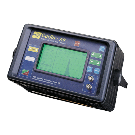
1. INTRODUCTION First and foremost we at NDT Systems, would like to thank you for your purchase of the ALL NEW Curlin- AIR , portable airborne ultrasonic flaw detector. The Curlin-AIR has been designed for airborne non-contact or dry-coupled contact ultrasonic flaw detection applications when used in conjunction with a special AT1 ultrasonic transducer. -
Page 8: Specifications
2.0 Specifications Display Super Twist LCD, 4.8 x 2.4 inches ( 122 x 61mm), transflective; backlit, adjustable contrast, battery status and mode icons, large thickness/soundpath display. Hollow or filled waveform, reversed field selectable. Display Mode Full-wave rectified. Graticule Graphically Generated, 10 x 10 major divisions Receiver 0.5 to 25 MHZ Broadband, Tuned 0.5, 1.0, 2.25, Frequency 5.0,... - Page 9 Transducer Cable BNC Connectors. Connectors Size Weight (Including Approximately 6.3 pounds Battery Pack)
-
Page 10: Operator Qualifications
3.0 Operator Qualifications The Curlin AIR's concept and design makes it the most unique ultrasonic flaw detector available. In order for the owner of this advanced technology instrument to fully benefit from the unique features of Curlin AIR, the assigned operator(s) must be experienced and well-founded in the fundamentals of ultrasonic testing. -
Page 12: Menu Descriptions
5.0 MENU DESCRIPTIONS One of the significant features of the Curlin AIR is the Direct Access Keypad. You can perform a simple calibration without the use of any menus whatsoever! Range and Gain are just a single color coded keystroke away.They are also, just about the only keys you’ll need to calibrate the Curlin AIR!! Also present on the... -
Page 13: Energy
With limited space available, some menu items are abbreviated. None-the-less, abbreviations and acronyms represent terms familiar to qualified ultrasonic NDT personnel. Curlin AIR is based upon a microprocessor, combining in high-speed digital electronic technology and new high capability ultrasonic instrument features. The following is a description of each Menu item(s) and its associated sub-functions. -
Page 14: Blnkadj
envelope. This feature has helped “clean” up the screen for easier interpretation. When blanking is set to TRACK, the leading edge is the reference point for the blank function. This allows the waveform to move horizontally on the screen (due to variation in velocity or transducer spacing) while still maintaining the blank function relative to the leading edge of the waveform. -
Page 15: Level
LEVEL GATE level allows adjustment of the threshold level of the gate. Adjustable from 10% to 90% of full screen height in 1% increment. IF IN DISTance MODE (refer to Fig 8) VELOCITY (VEL) Sets the material velocity (inches/microsecond or mm/microsecond) used in calculations of thickness. -
Page 16: Freeze
Figure 9 - Hollow, Smoothed, No Grid Figure 10 - Hollow DISP Figure 11 - Hollow Smoothed SAMPLES OF VARIOUS DISPLAY SCHEMES Figure 13 - Solid, Smoothed, No Grid Figure 12 - Hollow, Grid, Numbers FREEZE When activated stops any screen activity and “holds” whatever was on the screen at the time the freeze option was selected. -
Page 17: Rcall
Stores the Ultrasonic setup currently in use. 1 - 50 setups can be stored. A user defined, 16 char comment can be applied to each saved setup. When the cursor is on the SAVE or RECALL field the comment for that setup is displayed on the status line. The parameter LIST allows the user to see and select from a list off all stored setups with their comments. -
Page 18: Curlin Air Setup And Operating Considerations
One good check method is to first “calibrate” the Curlin-AIR on a reference sample flaw (see prior calibrating instructions). Next turn the instrument’s power OFF, disconnect the transmitter coaxial cable from the front panel BNC connector and, then, turn the power ON again. -
Page 19: Curlin Air Display Characteristics
Curlin AIR, particular attention has been paid to minimizing the number of menus and simplifying the process of locating desired functions. To some extent, once the operator is familiar with the operation, digitally controlled instruments are easier, more intuitive to operate than analog types. 6.7 Curlin AIR Display Characteristics A difference noticed by experienced operators of analog-type instruments is in the "stair-step"... -
Page 20: Flaw Detection Procedures
Curlin-AIR’s front panel. Electronic Initialization & Checkout 7.2.1 Power-ON. Turn on the Curlin-AIR by pressing the green/red button in the lower left-hand corner of its front panel. 7.2.2 Message Display The first message on the display screen will ask you to select or not select to use a backlit screen (for use in darkened areas). -
Page 21: Calibration
CALIBRATION 7.3.1 “Calibration” On Reference Samples Before actual use for inspection use, the Curlin-AIR must be adjusted so it will reliability detect and trigger the ALARM (audible &/or visual) whenever the ultrasonic beam is scanned over the minimum-size flaw that needs to be detected. -
Page 22: Keep Equipment Clean
THE TRANSDUCERS IN WATER!!! This WILL damage them. The technology behind the Curlin-AIR is a novel approach to industrial ultrasonic inspection both in concept and in practice. As a result the transducers are not conventional in fabrication and will not tolerate submersion as typical immersion transducers do. -
Page 23: Output And Optional Printer Technical Specifications
25 pin D Male connector to printer on the Curlin AIR Figure 5.2.1 Communications Connection The NDT systems part number for this cable is TE232. One was included with the instrument when shipped. Please use this part number when ordering replacement cables. NOTE: IBM compatible computers may incorporate several types of RS-232 connection schemes. -
Page 24: Battery Pack And Charger
9.0 Battery Pack and Charger The Curlin AIR is powered by 5 replaceable ‘D’ style batteries inserted into the rear panel via the rear panel access door. The Curlin AIR is shipped with 5 Hi Capacity rechargeable NiCad batteries installed along with an external battery charger. Once fully charged the Curlin AIR will run for up to 6+ hours before requiring another charge. -
Page 25: Optional Curlin Air Accessories
Section 6.0, Outputs. An interconnecting cable is included. Other Optional Printers - Contact NDT Systems for information about other printers that can be used with Curlin AIR. In some cases, custom interconnecting cables can be... -
Page 26: Warranty
Purchaser's exclusive remedy will be the return of the purchase price for the instrument. The liability of NDT Systems shall in no event be greater then the full amount of the purchase price for the instrument. - Page 27 NDT Systems Except as provided herein, no person is authorized to assume on behalf of NDT Systems any other or additional liability or responsibility in connection with the instrument. These terms and warranty are applicable to and complete acceptance of such a binding legal agreement.