Advertisement
Quick Links
INTRODUCTION:
Before installing this Serial Communication Option kit, a TECHNICALLY QUALIFIED INDIVIDUAL,
who is familiar with this type of equipment and hazards involved, should READ this ENTIRE
INSTRUCTION SHEET.
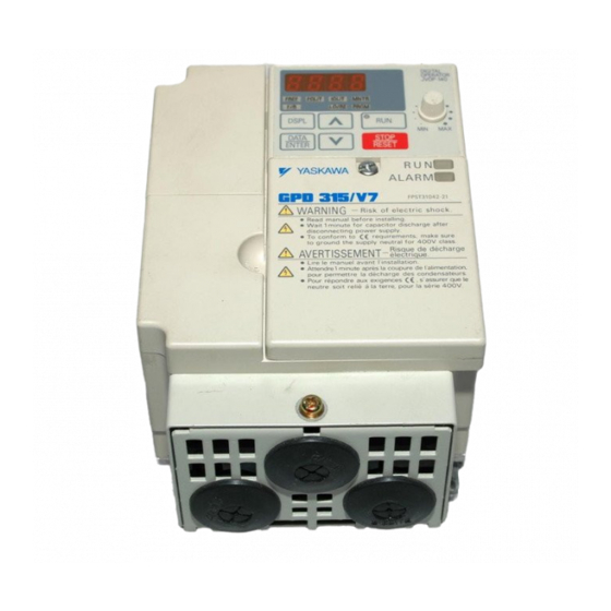
The Serial Communication Option Kit is an add-on assembly for the GPD315/V7 Adjustable
Frequency Drive.
KIT CONTENTS:
Unpack the Serial Communication Option Kit (Yaskawa Part No.:CM___). The following
should be present:
1. Yaskawa Document Entitled Outline of Option Assembly Kit (Product Information No.
99001).
2. Plastic bag containing one (1) M3X8.5 Decorative Screw, one (1) pan-head screw, two (2)
blue ground wires and one metal connection plate.
3. If Devicenet, one (1) data diskette (Yaskawa Part No.:49S03011-0000).
4. If Profibus, one (1) data diskette (Yaskawa Part No.: 46S03470-0010).
5. If CANOpen, one (1) data diskette (Yaskawa Part No.:49S03016-0000).
6. Assembled Serial Communication Option Ring Kit (Yaskawa Part No.: 05P00613-0020).
7. GPD315/V7 Communication Option Manual (Yaskawa Part No.: TM followed by four digit
number depending on given serial protocol).
ALL POWER AND CONTROL WIRING TO THE GPD315/V7 SHOULD BE INSTALLED
BEFORE CONNECTING THIS SERIAL KIT TO THE DRIVE.
IMPORTANT
POWER TO DRIVE SHOULD BE TURNED OFF!
Serial Communication Option Kit
for GPD 315/V7
Yaskawa Electric America Inc-www.drives.com
02Y00025-0514 Page 1 of 8
Date: 08/23/01
Advertisement

Related Manuals for YASKAWA GPD 315/V7


Summary of Contents for YASKAWA GPD 315/V7
- Page 1 5. If CANOpen, one (1) data diskette (Yaskawa Part No.:49S03016-0000). 6. Assembled Serial Communication Option Ring Kit (Yaskawa Part No.: 05P00613-0020). 7. GPD315/V7 Communication Option Manual (Yaskawa Part No.: TM followed by four digit number depending on given serial protocol).
- Page 2 Serial Communication Option Kit for GPD 315/V7 INSTALLATION: Note: Figure 1 Intentionally deleted. 1) Remove top screw from faceplate 2) Remove the faceplate from the drive and remove bottom screw (highlighted by bottom circle in Figure 2). Figure 2 3) After the screw is removed, the NEMA1 Endcap Bracket can be pulled off.
- Page 3 Serial Communication Option Kit for GPD 315/V7 4) Remove the digital operator from the top portion of the drive assembly. Drive should now appear as shown in Figure 4. Figure 4 5) Use a diagonal side cutters to cut the three plastic tabs...
- Page 4 Serial Communication Option Kit for GPD 315/V7 6) The CN2 port should be exposed (highlighted by black arrow: Figure 6) after performing this operation. Figure 6 7) The backside of the Serial Communication Option Kit is shown in Figure 7. Make sure that the blue ground...
- Page 5 Serial Communication Option Kit for GPD 315/V7 8) Remove Philips-head Ground screw and associated washer from the GPD315/V7 (white circle in Figure 8 and also shown previously in Figure 3). Put this screw through the blue wire lug on the Serial Communication Option Kit, and the put the washer back on the screw.
- Page 6 Serial Communication Option Kit for GPD 315/V7 10) Remove the pan-head screw (brass- colored) and the metal connection plate from the plastic bag containing hardware. There are two holes in the connection plate: One is for the pan-head screw, and one is for the plastic mounting hub.
- Page 7 Serial Communication Option Kit for GPD 315/V7 12) Snap Serial Communication Kit securely in place as shown in Figure 12. Figure 12 13) Remove Decorative M3X8.5 Screw from plastic bag (silver colored) and place in recessed circular hole at top of Serial Communication Kit (where screwdriver is presently located in Figure 13).
- Page 8 Serial Communication Option Kit for GPD 315/V7 14) Install Digital Operator as shown in Figure 14. Figure 14 15) Reinstall faceplate and associated screw. Figure 15 Physical installation of the kit is now complete. For electrical and software set-up, consult the manual accompanying this kit as well as the GPD315/V7 Technical Manual that accompanies the drive.