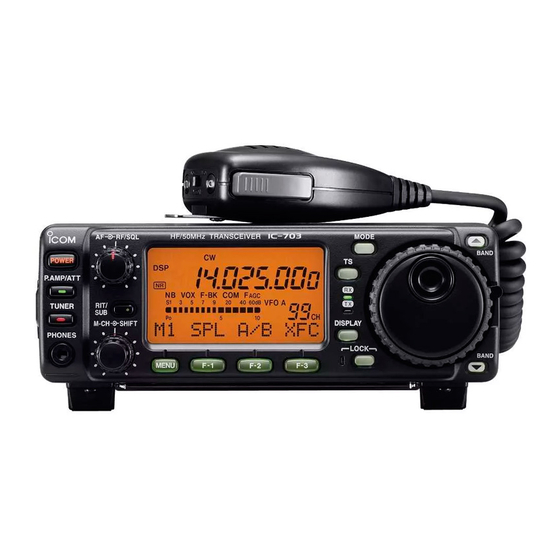
Icom IC-703 Installing Manual
Lif port into the transceiver
Hide thumbs
Also See for IC-703:
- Instruction manual (112 pages) ,
- Service manual (78 pages) ,
- Instruction manual (9 pages)
Advertisement
Quick Links
Installing a LIF port into the IC-703 transceiver
Introduction
This document describes the procedure for installing a LIF (Low Intermediate
Frequency [9 – 18kHz]) port into the FT-950 transceiver. This procedure requires
a level of expertise sufficient to dismantle the transceiver and to solder.
Nonetheless, the installation is straight forward and should not cause any
difficulties for the experienced radio amateur.
It is important to unplug all connectors and power before working on any
transceiver. It is also important to be grounded to avoid static discharges.
Please note: no responsibility or liability will be taken by the author of this
document for any damage or malfunction caused by user modifications.
LIF port installation
Dismantling the Transceiver
The top cover of the radio must be removed. There are 8 screws that need
to be removed and then the lid will come loose. Remove the lid carefully
because the speaker cable will still be connected to the circuit board.
Unplug the speaker. Now remove all the screws that hold down the PCB
(9 in total). The three white ribbon cables have to be unplugged by slightly
pulling on them. The two coaxial cables in back have to be gently
unplugged. Now the board can be twisted out, starting at the front.
Drilling the Hole
A SMA connector is the preferred connector because of its small size. A
BNC or a RCA connector will also work in the case that a SMA connector
is not available. A hole will need to be drilled next to the phone plug for the
Morse key. Make sure the hole clears the screw stud and is high enough
to allow space for the coaxial cables.
Before drilling the hole, cover all the cutouts to the lower PCB with
masking tape to prevent metal shavings from falling into the lower part of
the transceiver. Blow out the metal dust and clean the surfaces of all dust
before reassembling.
Advertisement

Related Manuals for Icom IC-703


Summary of Contents for Icom IC-703
- Page 1 Installing a LIF port into the IC-703 transceiver Introduction This document describes the procedure for installing a LIF (Low Intermediate Frequency [9 – 18kHz]) port into the FT-950 transceiver. This procedure requires a level of expertise sufficient to dismantle the transceiver and to solder.
- Page 2 Connecting the RG174 cable to the PCB The 455kHz bidirectional port of the IC-703 is on the bottom side of the top circuit board. The RG174 cable center is soldered onto a 1nF ceramic decoupling capacitor. The Layout design drawing (left) and the picture of the actual PCB (below).
- Page 3 Setup of the CAT interface The MDSR software controls the transceiver via the CAT port. The connector cable CI-V is the Icom version of the interface cable that plugs into the back of the radio and the RS-232 port of the computer. There are also virtual RS-232 cables available that connect via the USB bus to the computer.
- Page 4 OmniRig Setup for the IC-703 series transceivers To enter setup menu in MDSR-SA, select the tool icon at the bottom right and select “OmniRig Configuration & Status”, select the key icon “Configure OmniRig”. Only configure RIG 1. • Select the transceiver to be controlled from the drop down menu (IC-703).