
Related Manuals for Meyer Sound SB-1

Summary of Contents for Meyer Sound SB-1
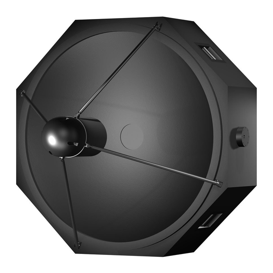
- Page 1 Operating Instructions SB-1 Parabolic Sound Beam Copyright 1998 Meyer Sound Laboratories, Inc. All rights reserved Part Number 05.049.048.01 A...
-
Page 2: Table Of Contents
Meyer Sound Laboratories Product Options: All Address: 2832 San Pablo Avenue Berkeley, California 94702-2204, USA Environmental Specifications for conforms to the following Product Specifications: Meyer Sound Electronics Products Safety: EN 60065: 1994 Operating temperature: 0° C to +45° C EMC:... -
Page 3: Ac Power
The AC voltage operating ranges for the SB-1 are to understand the types of current ratings and how they 85 – 134 V and 165 – 264 V, at 50 or 60 Hz. The SB-1 correspond to circuit breaker and cable specifications. -
Page 4: Audio Input
(ESD clamped) Pin 2 — Signal Differential Inputs Use a power cord adapter to drive the SB-1 from a Pin 3 — Signal standard 3-prong outlet (NEMA 5-15R; 125 V max). Case — Earth (AC) ground and chassis Pins 2 and 3 carry the input as a differential signal;... -
Page 5: Ac Troubleshooting
Contact Meyer Sound for second. If the LEDs remain on for longer than three repair information. seconds, the SB-1 is hard limiting with these negative consequences: If abnormal noise (hum, hiss, popping) is produced from the loudspeaker, disconnect the audio source from the •... -
Page 6: Fans And Cooling Systems
The SB-1 uses a forced-air cooling system with two fans airflow, preventing normal cooling. We recommend to prevent the amplifiers from overheating. A variable-speed... - Page 7 ” On the top of the SB-1 is a single rigging point which can threaded rigging hole on both sides of the SB-1 be used to hang the SB-1 for easy yoke installation and removal.
-
Page 8: Cover Removal And Installation
While pressing down on the cover, push the button at The high frequency pod will be attached to the SB-1 using the top of the pin in, while pulling the pin out of the C- the same c-brackets and locking pins which held the dish bracket. -
Page 9: Driver Phase Verification
500 Hz is acceptable. of the pod to the surface of the dish must be 13.25” inches Set up the SB-1 so that it is powered and reproducing +/- 0.25” . If the distance does not match this specification the noise from the generator. -
Page 10: Safety Summary
Safety Summary English Français • To reduce the risk of electric shock, disconnect the loud- • Pour réduire le risque d’électrocution, débranchez la prise speaker from the AC mains before installing audio cable. principale de l’haut-parleur, avant d’installer le câble Reconnect the power cord only after making all signal d’interface allant à... -
Page 11: Controls And Connectors
Front Side 54.0 18.0 54.0 48.5 Weight: SB-1: 293 lb (133 kg); SB-1 with yoke: 392 lb (178 kg) Contact Information Meyer Sound Laboratories, Inc. Meyer Sound Germany GmbH 2832 San Pablo Avenue Carl Zeiss Strasse 13 Berkeley, California 94702...